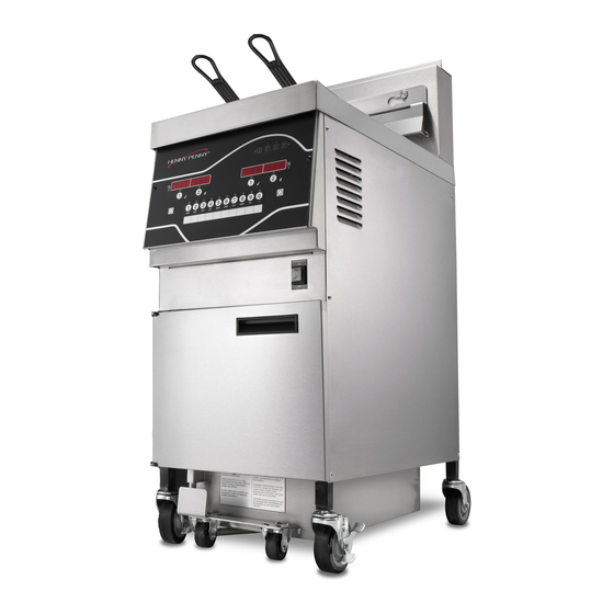
Henny Penny Evolution Elite EEE-141 Operator's Manual
Reduced oil capacity open fryer
Hide thumbs
Also See for Evolution Elite EEE-141:
- Technical manual (158 pages) ,
- Operator's manual (63 pages) ,
- Quick manual (2 pages)
Table of Contents
Advertisement
Advertisement
Table of Contents

Related Manuals for Henny Penny Evolution Elite EEE-141


Summary of Contents for Henny Penny Evolution Elite EEE-141
- Page 1 OPERATOR E E v v o o l l u u t t i i o o n n E E l l i i t t e e ™ ™ MANUAL ( ( E E l l e e c c t t r r i i c c ) ) R R e e d d u u c c e e d d O O i i l l C C a a p p a a c c i i t t y y O O p p e e n n F F r r y y e e r r EEE-141...
-
Page 3: Table Of Contents
Table of Contents Safety and Compliance....................vii Chapter 1 Introduction.....................1 1.1 Introduction ......................1 1.2 Features........................1 1.3 Proper Care......................1 1.4 Assistance......................1 Chapter 2 Installation ......................3 2.1 Introduction ......................3 2.2 Unpacking ......................3 2.3 Selecting The Fryer Location ..................4 2.4 Leveling The Fryer ....................5 2.5 Ventilation Of Fryer ....................5 2.6 Electrical Requirements..................5 2.7 Dimensions ......................8... - Page 4 3.19 Check/Replace Drain Pan O-Rings..............44 3.20 Info & Filter Button Stats ..................46 3.20.1 Filter Button Stats..................47 3.20.2 Info Button Stats ..................47 3.21 Preventative Maintenance Schedule..............47 Chapter 4 Information Mode ..................49 4.1 E-Log ........................49 4.2 Last Load ......................50 4.3 Daily Stats ......................50 4.4 Oil Stats ......................51 4.5 Review Usage .....................52 4.6 USB SUPPORT ....................53...
- Page 6 List of Tables Table 3-1 Operating Controls & Indicators .................12 Table 3-2 Operating Components ..................14 Table 3-3 Set-Up Mode Items ...................14 Table 3-4 Oil Capacities ....................16 Table 3-5 Filter Button Stats .....................47 Table 3-6 Info Button Stats ....................47 Table 3-7 Preventative Maintenance Schedule ..............47 Table 6-1 Special Program Modes ..................59 Table 6-2 Special Programming Details................61 Table 7-1 Troubleshooting....................69...
- Page 7 Figure 3-25 Clean Drain Pan ....................38 Figure 3-26 Aligning Filter Tube & Fitting ................38 Figure 3-27 Engaged Drain Pan Stop................39 Figure 3-28 Basket Rest ....................39 Figure 3-29 Filter Drain Pan O-Rings ................45 Figure 3-30 Drain Pan Latch Lifted..................45 Figure 3-31 Pulling Out Drain Pan..................46 Figure 3-32 Replacing O-Ring ..................46...
-
Page 9: Features
S S a a f f e e t t y y a a n n d d C C o o m m p p l l i i a a n n c c e e Henny Penny fryers have many safety features incorporated. However, the only way to ensure safe operation is to fully understand the proper installation, operation, and maintenance procedures. -
Page 10: Chapter 2 Installation
These are the original version controlled Henny Penny instructions for Evolution Elite Electric (EEE) model 141, 142, 143, 144. This manual is available on the Henny Penny Public website (www.hennypenny.com). Read these instructions completely prior to installation and operation of this appliance to ensure compliance to all required installation, operation and safety standards. - Page 11 Hazardous Substances directive (RoHS) and have redesigned our products as needed in order to comply. To continue compliance with these directives, this unit must not be disposed as unsorted municipal waste. For proper disposal, please contact your nearest Henny Penny distributor.
- Page 13 1 1 . . 1 1 I I n n t t r r o o d d u u c c t t i i o o n n The Henny Penny open fryer is a basic unit of food processing equipment designed to cook foods better and easier.
-
Page 15: Unpacking
2 2 . . 1 1 I I n n t t r r o o d d u u c c t t i i o o n n This section provides the installation and unpacking instructions for the Henny Penny Evolution Elite®... -
Page 16: Figure 2-1 Unpacking Instructions
Figure 2-1 Unpacking Instructions T T a a k k e e c c a a r r e e w w h h e e n n m m o o v v i i n n g g t t h h e e f f r r y y e e r r t t o o p p r r e e v v e e n n t t p p e e r r s s o o n n a a l l i i n n j j u u r r y y . - Page 17 2 2 . . 4 4 L L e e v v e e l l i i n n g g T T h h e e F F r r y y e e r r For proper operation, the open fryer should be level from side-to-side and front to back.
-
Page 18: Figure 2-2 Cable Restraint
must be installed according to national and local codes. It should be an insulated copper conductor rated for 600 volts and 90° C. For runs longer than 50 feet (15.24 m), use the next larger wire size. CE units require a minimum wire size of 6 mm to be wired to the terminal block. - Page 19 The supply power cords shall be oil-resistant, sheathed flexible cable, no lighter than ordinary polychloroprene or other equivalent synthetic elastomer-sheathed cord.
-
Page 20: Figure 2-3 Eee-14X Dimensions
2 2 . . 7 7 D D i i m m e e n n s s i i o o n n s s Figure 2-3 EEE-14X Dimensions • Front to rear dimension is 36- 7/8 “ (93.66 cm). I I N N F F O O : •... -
Page 21: Figure 2-4 Protective Bumper Bar
Figure 2-4 Protective Bumper Bar... -
Page 23: Table 3-1 Operating Controls & Indicators
C C h h a a p p t t e e r r 3 3 O O p p e e r r a a t t i i o o n n 3 3 . . 1 1 O O p p e e r r a a t t i i n n g g C C o o m m p p o o n n e e n n t t s s The operating controls and indicators are shown in Figure 3-1 Operating Controls &... -
Page 24: Chapter 3 Operation
T T a a b b l l e e 3 3 - - 1 1 O O p p e e r r a a t t i i n n g g C C o o n n t t r r o o l l s s & & I I n n d d i i c c a a t t o o r r s s Item No. -
Page 25: Figure 3-2 Operating Components
Item No. Description Function Right Timer 1 During normal operation, press this button to start and stop Button cook cycles for the right basket; press to change displayed product; also used for √ to indicate YES or to confirm. Right Timer 2 During normal operation, press this button to start and stop Button cook cycles for the right basket;... -
Page 26: Table 3-2 Operating Components
T T a a b b l l e e 3 3 - - 2 2 O O p p e e r r a a t t i i n n g g C C o o m m p p o o n n e e n n t t s s Item. - Page 27 Menu Step Description Daylight Saving “1.OFF”; “2.US” (2007 & after); “3.EURO”; “4.FSA” (US before 2007). Time Fryer Type “ELEC” or “GAS”. Vat Type “FULL” or “SPLIT”. Autolift Enabled? “NO LIFT” or “YES LIFT”. Bulk Oil Supply “YES” or “NO”. Bulk Oil “YES”...
-
Page 28: Table 3-4 Oil Capacities
T T a a b b l l e e 3 3 - - 4 4 O O i i l l C C a a p p a a c c i i t t i i e e s s Vat Type Oil Capacity Full... - Page 29 3 3 . . 4 4 M M o o r r n n i i n n g g S S t t a a r r t t - - U U p p P P r r o o c c e e d d u u r r e e s s •...
-
Page 30: Idle Mode
Press any of the four timer buttons. (Auto-lift fryers, the basket automatically 2 2 ) ) lowers into the shortening.) Display shows the name of the product cooking (ex: “FRY”) and the timer 3 3 ) ) counting down. When cook cycle is complete, and alarm sounds and display shows “DONE”. 4 4 ) ) Press the timer button under “DONE”... -
Page 31: Figure 3-4 Disconnecting Jib
3 3 . . 8 8 S S e e l l e e c c t t i i n n g g A A P P r r o o d d u u c c t t W W i i t t h h A A D D i i f f f f e e r r e e n n t t S S e e t t - - P P o o i i n n t t When selecting a product, if “XXX XXX”... -
Page 32: Figure 3-5 Removing Reservoir Lid
Figure 3-5 Removing Reservoir Lid Place reservoir cover on bracket on door. See Figure 3-6 Reservoir in Bracket , 3 3 ) ) page Figure 3-6 Reservoir in Bracket Pour oil into reservoir up to fill lines (13 lbs. (6.12 kg.)) and then replace cover 4 4 ) ) and push reservoir back into position. -
Page 33: Figure 3-7 Reservoir Fill Line
Figure 3-7 Reservoir Fill Line 3 3 . . 1 1 0 0 . . 2 2 R R e e m m o o v v i i n n g g / / C C l l e e a a n n i i n n g g R R e e s s e e r r v v o o i i r r Open door and pull reservoir forward. -
Page 34: Figure 3-9 Replacing O-Ring
Figure 3-9 Replacing O-Ring 3 3 . . 1 1 1 1 F F i i l l t t e e r r i i n n g g T T h h e e S S h h o o r r t t e e n n i i n n g g 3 3 . -
Page 35: Figure 3-11 Drain Knob Closed
T T o o a a v v o o i i d d o o v v e e r r f f i i l l l l i i n n g g t t h h e e d d r r a a i i n n p p a a n n , , d d r r a a i i n n o o n n l l y y 1 1 v v a a t t a a t t a a t t i i m m e e . -
Page 36: Automatic
F F i i l l t t e e r r E E r r r r o o r r After trying to fill the vat 3 times without success, the display shows “*CHANGE* 8 8 ) ) *FILTER* *PAD* CLOGGED?”. -
Page 37: Changing The Filter Pad
Display shows “IS POT FILLED?” “YES NO”. Press ✓ button and control returns 7 7 ) ) to normal operation. Press “X” button and pump runs for another 30 seconds. You can try to fill the vat 3 times. After trying to fill the vat 3 times without success, the controls then shows 8 8 ) ) “CHANGE FILTER PAD?”... - Page 38 Press the ✓ button for “YES” and display shows “CONFIRM”, followed by “YES 4 4 ) ) NO”. Press the ✓ button for “YES”; display shows “OPEN DRAIN”. Pull-out on the 5 5 ) ) drain knob , the display shows “DRAINING” and the oil drains from the vat, or press the “X”...
- Page 39 Once the vat is filled, “OPEN DRAIN” shows in display. Pull-out on drain knob to 1 1 2 2 ) ) open the drain and display shows “RINSING”. When rinsing is complete, display shows “RINSE AGAIN?” “YES NO”. Press the ✓ button for “YES” if another rinse is needed, otherwise press the “X” 1 1 3 3 ) ) button for “NO”.
- Page 40 U U s s e e p p r r o o t t e e c c t t i i v v e e c c l l o o t t h h o o r r g g l l o o v v e e s s w w h h e e n n l l i i f f t t i i n n g g t t h h e e b b a a s s k k e e t t s s u u p p p p o o r r t t .
-
Page 41: Figure 3-12 Drain Pan Latch Lifted
3 3 . . 1 1 3 3 D D i i s s c c a a r r d d i i n n g g O O i i l l F F r r o o m m V V a a t t U U s s i i n n g g O O p p t t i i o o n n a a l l O O i i l l D D i i s s c c a a r r d d S S h h u u t t t t l l e e 3 3 . - Page 42 Press ✓ button and “IS DISPOSAL UNIT IN PLACE?" “YES NO” shows in 4 4 ) ) display. With discard shuttle rolled into place (Figure 3), press ✓ button and display 5 5 ) ) shows “OPEN DRAIN”. Pull-out on drain knob to open drain and display shows “DRAINING”.
-
Page 43: Figure 3-14 Front Dispose Hose
3 3 . . 1 1 4 4 D D i i s s c c a a r r d d i i n n g g O O i i l l F F r r o o m m V V a a t t U U s s i i n n g g O O p p t t i i o o n n a a l l F F r r o o n n t t D D i i s s p p o o s s e e S S y y s s t t e e m m I I N N F F O O : “BULK OIL DISPOSE?”... -
Page 44: Figure 3-15 Attaching Quick-Disconnect
Figure 3-15 Attaching Quick-Disconnect Display shows “HOLD DISPOSE SWITCH” and “X=DONE”. While holding the 1 1 0 0 ) ) wooden handle, make sure hose nozzle is pointed into the disposal container and then press and hold dispose switch to pump oil from drain pan. See Figure 3-16 Dispose Switch , page Figure 3-16 Dispose Switch... -
Page 45: Figure 3-17 Filter Beacon Lit
Figure 3-17 Filter Beacon Lit Display shows “MANUAL FILL VAT” (or “FILL VAT FROM BULK if so 1 1 2 2 ) ) equipped), followed by “IS POT FILLED?”, along with “YES NO”. Fill the vat to the lower indicator line on the rear of the vat. See 3.3 Filling Or Adding Oil , page 15. -
Page 46: Figure 3-18 Drain Pan Latch Lifted
Display shows “DISPOSE” and then “✓=PUMP” “X=DONE”. Press ✓ button. 9 9 ) ) Display shows “DISPOSING...” “X=STOP” and oil is pumped from drain pan to 1 1 0 0 ) ) bulk oil container. When all oil is pumped from pan, press “X” button (STOP). Display shows “DISPOSE”... -
Page 47: Figure 3-19 Pulling Out Drain Pan
Figure 3-19 Pulling Out Drain Pan • T T h h i i s s p p a a n n c c o o u u l l d d b b e e h h o o t t ! ! U U s s e e p p r r o o t t e e c c t t i i v v e e c c l l o o t t h h o o r r g g l l o o v v e e o o r r s s e e v v e e r r e e b b u u r r n n s s c c o o u u l l d d r r e e s s u u l l t t . -
Page 48: Figure 3-21 Removing Crumb Basket
Figure 3-21 Removing Crumb Basket Remove the filter pad retaining ring and clean thoroughly with soap and water. 5 5 ) ) Rinse thoroughly with hot water. See Figure 3-22 Removing Filter Pan Retaining Ring , page Figure 3-22 Removing Filter Pan Retaining Ring Pull the filter pad from the pan and discard pad. -
Page 49: Figure 3-23 Removing Filter Pad
Figure 3-23 Removing Filter Pad Remove the bottom screen from pan and clean thoroughly with soap and water. 7 7 ) ) Figure 3-24 Removing Bottom Screen , Rinse thoroughly with hot water. See page Figure 3-24 Removing Bottom Screen Wipe the oil and crumbs from the drain pan. -
Page 50: Figure 3-25 Clean Drain Pan
Figure 3-25 Clean Drain Pan NOTICE : Be sure that drain pan, bottom screen, crumb catcher, and the retaining ring are thoroughly dry before placing filter pad into pan as water will dissolve the filter pad. Reassemble in reverse order, placing the bottom screen into the filter pan first, 9 9 ) ) followed by the filter pad, retaining ring and the crumb catcher. -
Page 51: Figure 3-27 Engaged Drain Pan Stop
Figure 3-27 Engaged Drain Pan Stop 3 3 . . 1 1 7 7 R R e e m m o o v v i i n n g g & & C C l l e e a a n n i i n n g g B B a a s s k k e e t t R R e e s s t t The basket rest, on the rear shroud of the fryer, should be removed and cleaned periodically. - Page 52 3 3 . . 1 1 8 8 C C l l e e a a n n - - O O u u t t M M o o d d e e 3 3 . . 1 1 8 8 . . 1 1 M M a a n n u u a a l l C C l l e e a a n n - - O O u u t t M M o o d d e e •...
- Page 53 Display shows “SOLUTION ADDED?” “YES NO”. Fill vat with hot water to 1 in. 6 6 ) ) (25 mm) above the top fill line, add 4 oz. (0.12 liters) of open fryer cleaner, and mix thoroughly. Press ✓ button and display shows “START CLEAN” “YES NO”. Press ✓...
- Page 54 Pull drain pan from under fryer and dispose of rinse water. 1 1 6 6 ) ) Thoroughly dry the vat with a towel, and then press the ✓ button. Controls return 1 1 7 7 ) ) to normal operations. Make sure drain is closed.
- Page 55 “DISPOSE?” “YES NO”. Press ✓ button to dispose of the oil, or press “X” button to exit Clean-Out Mode. Display shows “IS DISPOSAL UNIT IN PLACE” “YES NO”. If “NO” is selected, display shows “INSERT DISPOSAL UNIT”. Once disposal unit is in place, press ✓...
- Page 56 • D D o o n n o o t t u u s s e e s s t t e e e e l l w w o o o o l l , , o o t t h h e e r r a a b b r r a a s s i i v v e e c c l l e e a a n n e e r r s s , , o o r r c c l l e e a a n n e e r r s s / / s s a a n n i i t t i i z z e e r r s s c c o o n n t t a a i i n n i i n n g g c c h h l l o o r r i i n n e e , , b b r r o o m m i i n n e e , , i i o o d d i i n n e e , , o o r r a a m m m m o o n n i i a a c c h h e e m m i i c c a a l l s s a a s s t t h h e e s s e e w w i i l l l l d d e e t t e e r r i i o o r r a a t t e e t t h h e e s s t t a a i i n n l l e e s s s s s s t t e e e e l l m m a a t t e e r r i i a a l l a a n n d d s s h h o o r r t t e e n n t t h h e e l l i i f f e e o o f f t t h h e e...
-
Page 57: Figure 3-29 Filter Drain Pan O-Rings
Figure 3-29 Filter Drain Pan O-Rings Open the door, lift-up on the drain pan stop and pull-out the filter drain pan 1 1 ) ) assembly, using the handle on the drain pan. See Figure 3-30 Drain Pan Latch Lifted , page 45 Figure 3-31 Pulling Out Drain Pan , page Figure 3-30 Drain Pan Latch Lifted... -
Page 58: Figure 3-31 Pulling Out Drain Pan
Figure 3-31 Pulling Out Drain Pan T T h h i i s s p p a a n n c c o o u u l l d d b b e e h h o o t t ! ! U U s s e e p p r r o o t t e e c c t t i i v v e e c c l l o o t t h h o o r r g g l l o o v v e e , , o o r r s s e e v v e e r r e e b b u u r r n n s s c c o o u u l l d d r r e e s s u u l l t t . -
Page 59: Table 3-5 Filter Button Stats
3 3 . . 2 2 1 1 P P r r e e v v e e n n t t a a t t i i v v e e M M a a i i n n t t e e n n a a n n c c e e S S c c h h e e d d u u l l e e As in all food service equipment, the Henny Penny open fryer does require care and proper maintenance. - Page 60 Procedure Frequency Changing of oil. When oil smokes, foams up violently, or tastes bad. Cleaning the vat. 3.18 Clean-Out Mode , Every change of oil. page 40 3.19 Check/Re- Inspect filter pan O-rings. Quarterly. place Drain Pan O-Rings , page 44 Inspect EEE-141 reservoir O-rings.
-
Page 61: Chapter 4 Information Mode
I I N N F F O O : Not all Information Mode functions are discussed in this section. To ensure proper operation of fryer, please consult Henny Penny Corp. before changing any of these settings. For more information on these functions, contact Technical Support at 1-800-417-8405, or 1-937-456-8405. -
Page 62: Last Load
Press the down arrow button and if an error was recorded, “B. (date, time, and 3 3 ) ) error code information)” shows in display. This is the latest error code that the controls recorded. Sometimes the characters “L:” and “R:” appear in front of the error code on the display which refers to the left or right vat of a split vat. -
Page 63: Oil Stats
Press the right arrow button and ”3. DAILY STATS” shows in displays. 1 1 ) ) Press the down arrow button to start viewing the cook data. 2 2 ) ) Press product button 1 to view data for other days of the week. 3 3 ) ) Function Display Example... -
Page 64: Review Usage
Function Display Example Start Date Of New Oil (L/R) NEW OIL MAR-23 Number Of Days Oil In Use (L/R) OIL USE 4 DAYS Number Of Filters On This Oil (L/R) FILTERD Number Of Times Filter Skipped (L/R) SKIPPED Number Of Cook Cycles On This Oil (L/R) TOT CK Average Number Of Days Per Oil Change (L/R) AVG DAYS... - Page 65 Function Display Example Cook Cycles for Product #3 COOK -3- Cook Cycles for Product #4 COOK -4- Cook Cycles for Product #5 COOK -5- Cook Cycles for Product #6 COOK -6- Cook Cycles for Product #7 COOK -7- Cook Cycles for Product #8 COOK -8- Cook Cycles for Product #9 COOK -9-...
- Page 67 C C h h a a p p t t e e r r 5 5 P P r r o o d d u u c c t t P P r r o o g g r r a a m m M M o o d d e e This mode allows you to program the following: •...
- Page 68 Press the right arrow button until “ASSIGN BTN” shows in the display, along 6 6 ) ) with the product (ex: NUGGETS). If this product already has a product button assigned to it, that LED will be lit. To assign other product buttons to that product, press and hold the product button for 3 seconds and that LED stays lit.
-
Page 69: Chapter 5 Product Program Mode
L L o o a a d d C C o o m m p p e e n n s s a a t t i i o o n n Press the right arrow button until “LD COMP” shows in the display along with the 1 1 4 4 ) ) load compensation value. -
Page 71: Table 6-1 Special Program Modes
C C h h a a p p t t e e r r 6 6 L L e e v v e e l l 2 2 P P r r o o g g r r a a m m m m i i n n g g Used to access the following: •... - Page 72 Program Code Description S S P P - - 5 5 Audio Tone (Frequency) S S P P - - 6 6 Melt Cycle Selection - 1.LIQUID; 2.SOLID S S P P - - 7 7 Idle Mode Enabled - YES or NO S S P P - - 7 7 A A Use “0”...
-
Page 73: Table 6-2 Special Programming Details
Program Code Description S S P P - - 2 2 5 5 Change Mgr. Code- 1 = YES S S P P - - 2 2 6 6 Change Usage Code - 1 = YES S S P P - - 2 2 7 7 Dispose Requires Code ? - YES or NO S S P P - - 2 2 8 8 Longer Fill Time Enabled - YES or NO... - Page 74 Menu Step Description SP-7 Idle Mode An Idle Mode allows the oil temperature to drop to a lower tempera- Enabled ture when not in use. This saves on oil and utilities. Press and release the right arrow button until “SP-7” “IDLE MODE ENABLED?” flashes in the left display.
- Page 75 Menu Step Description when controls suggest filtering, “FILTER LOCKOUT”/”YOU *MUST* FILTER NOW”, shows in display; more cook cycles are refused until vat is filtered. Press the right arrow button and “SP-8C” “FILTER LOCKOUT AT...” shows in left display and a value between 100% and 250% shows on right display.
- Page 76 Menu Step Description SP-9 Polish Press and the release the right arrow button until “SP-9 POLISH Duration TIME” flashes in the left display. Press the up and down arrow but- tons, or the product buttons, to change the polish time, from 0 to 10 minutes.
- Page 77 Menu Step Description being the loudest) and the seconds volume shows in the right display. To select the volume, press the ✓ button under the desired volume. SP-18 Energy Save Press and release the right arrow button until “SP-18 ENERGY SAVE Mode ENABLED?”...
- Page 78 Menu Step Description back to “SP-25” “CHANGE MGR CODE? 1=YES”. Now the above steps can be repeated. SP-26 Usage Code This allows the operator to change the reset usage code (factory set 4.5 Re- Change at 1, 2, 3) to reset the usage amounts of each product. See view Usage , page 52 in Information Mode.
- Page 79 Press the program button once more and “DO NOT DISTURB” “ENTER CODE” 2 2 ) ) flash in the left display. Enter code 1, 2, 3. 3 3 ) ) “DO NOT DISTURB ENABLED?” flashes in the left display and “YES” or “NO” 4 4 ) ) appears in the right display.
- Page 80 C C o o n n t t r r o o l l M M o o d d e e s s The Data Logging, Heat Control, Tech, Stat and Filter Control Modes are advanced diagnostic and program modes, mainly for Henny Penny use only. For more information on these modes, contact the Service Department at 1-800-417-8405 or 1-...
-
Page 81: Table 7-1 Troubleshooting
C C h h a a p p t t e e r r 7 7 T T r r o o u u b b l l e e s s h h o o o o t t i i n n g g 7 7 . -
Page 82: Table 7-2 Error Codes
Problem Cause Correction pumps oil Filter paper or Change filter paper or pad. slowly. pad clogged. Bubbles in Filter pan not Make sure filter pan return line is pushed completely into oil during completely the receiver on the fryer. entire filter- engaged. - Page 83 Display Cause Panel Board Correction “E-10” High limit. Let the unit cool down (15-20 minutes), insert the high limit tool, on the inside of the LH door, gently into the hole in the heating element hinge. If the high limit does not reset, high limit must be replaced.
- Page 84 Display Cause Panel Board Correction “E-60” AIF PC board not Turn power switch to off, wait 15 seconds, then turn switch communicating back to on. If “E-60 persists, have connector between the with PC board. PC boards checked; replace AIF PC board or control PC board if necessary.
- Page 85 blank page...
- Page 86 H H e e n n n n y y P P e e n n n n y y C C o o r r p p o o r r a a t t i i o o n n P P .