
Related Manuals for Henny Penny Evolution Elite EEG-142


Summary of Contents for Henny Penny Evolution Elite EEG-142
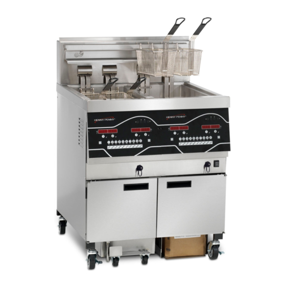
- Page 1 Henny Penny Evolution Elite™ Reduced Oil Capacity Open Fryers (Split Vat & Full Vat– Model EEG-142 Model EEG-143 Model EEG-144 TECHNICAL MANUAL...
-
Page 3: Table Of Contents
Model EEG-142, 143, 144 TABLE OF CONTENTS Section Page Section 1. TROUBLESHOOTING ................... 1-1 Introduction ....................1-1 Safety ......................1-1 Troubleshooting .................... 1-2 Error Code Table ..................1-7 Section 2. INFO & FILTER BUTTON STATS ..............2-1 INFO Button Stats ..................2-1 FILTER Button Stats .................. - Page 4 Model EEG-142, 143, 144 TABLE OF CONTENTS Section Page Section 6. MAINTENANCE SECTION (Continued) Solenoid Valves ....................6-9 Oil Channel Clean-Out ................... 6-11 6-10 Filter Pump & Motor ..................6-12 6-11 JIB Pump ......................6-14 6-12 Express Filter PC Board ................. 6-14 6-13 Transformers ....................
-
Page 5: Section 1. Troubleshooting
Model EEG-142, 143, 144 SECTION 1. TROUBLESHOOTING 1-1. INTRODUCTION This section provides troubleshooting information in the form of an easy to read table. If a problem occurs during the first operation of a new fryer, recheck the installation per the Installation Section of this manual. -
Page 6: Troubleshooting
Model EEG-142, 143, 144 1-3. TROUBLESHOOTING To isolate a malfunction, proceed as follows: 1. Clearly define the problem (or symptom) and when it occurs. 2. Locate the problem in the Troubleshooting table. 3. Review all possible causes. Then, one-at-a-time work through the list of corrections until the problem is solved. - Page 7 Model EEG-142, 143, 144 7-1. TROUBLE SHOOTING (Continued) Problem Cause Correction POWER switch ON • Open circuit • Plug fryer in but fryer completely • Check breaker or fuse at supply box inoperative Control error code “E-10” • Oil temperature too high • Let unit cool down (15-20 minutes), push up on metal reset button under right side of the controls;...
- Page 8 Model EEG-142, 143, 144 7-1. TROUBLE SHOOTING (Continued) Problem Cause Correction Oil foaming or boiling over • Water in oil • Drain and clean oil top of vat • Improper or bad oil • Use recommended oil Improper filtering Refer to filtering procedures •...
- Page 9 Model EEG-142, 143, 144 1-4. ERROR CODES In the event of a control system failure, the digital display shows an error message. The message codes are shown in the DISPLAY column below. A constant tone is heard when an er- ror code is displayed, and to silence this tone, press any button.
- Page 10 Model EEG-142, 143, 144 1-4. ERROR CODES (Continued) “E-20-A” • Pressure Switch • If fan is not running, have pressure switch “FAN SENSOR failure checked; should be open circuit if no air STUCK • Wiring problem pressure • I/O board failure CLOSED”...
- Page 11 Model EEG-142, 143, 144 1-4. ERROR CODES (Continued) Check filter system in Vat #2 “E-83-B” • Pressure too high • Check filter system in Vat #3 “E-83-C” • Pressure too high • Check filter system in Vat #4 “E-83-D” • Pressure too high •...
-
Page 12: Section 2. Info & Filter Button Stats
Model EEG-142, 143, 144 SECTION 2. INFO & FILTER BUTTON STATS Actual Oil Temperature 2-1. INFO BUTTON STATS 1. Press and the actual oil temperature shows in the display, for each vat. Set-point Temperature 1. Press twice and SP shows in the display, along with the set-point (preset) temperature of each vat. -
Page 13: Information Mode
Not all Information Mode functions are discussed in this section. To ensure proper operation of fryer, please consult Henny Penny Corp. before changing any of these settings. For more information on these functions, contact Technical Support at 1-800-417- 8405, or 1-937-456-8405. - Page 14 Model EEG-142, 143, 144 3-1. INFORMATION MODE 2. LAST LOAD (Information on recent cook cycles) Press ► and “2. LAST LOAD” show in displays. DETAILS (Continued) Press a timer button for the product you want to view the cook data and the LED flashes. Press ▼...
- Page 15 Model EEG-142, 143, 144 3-1. INFORMATION MODE 3. DAILY STATS (Operational info of fryer for last 7 days) Press ► and “3. DAILY STATS” show in displays. DETAILS (Continued) Press ▼ button to start viewing the cook data. Press the right to view data for other days of week.
- Page 16 Model EEG-142, 143, 144 3-1. INFORMATION MODE 4. OIL STATS DETAILS (Continued) (info of current oil and avg. of last 4 batches of oil) Press ► and “4. OIL STATS” show in displays. Press ▼ button to start viewing the cook data. FUNCTION DISPLAY EX: Start date of new oil...
- Page 17 Model EEG-142, 143, 144 3-1. INFORMATION MODE 5. REVIEW USAGE DETAILS (Continued) (accumulated info since the data was reset) Press ► and “5. REVIEW USAGE” show in displays. Press ▼ button to start viewing the cook data. FUNCTION DISPLAY EX: Day the usage data was previously reset SINCE APR-19 3:00P...
- Page 18 Model EEG-142, 143, 144 3-1. INFORMATION MODE 6. INPUTS Press ► and “6. INPTS” and “HDF” show in displays. DETAILS (Continued) H = HIGH LIMIT - If “H” is present, the high limit is good. If “-” shows then the high limit is tripped out (overheated) or discon- nected.
-
Page 19: Product Program Mode
Model EEG-142, 143, 144 SECTION 4. PRODUCT PROGRAM MODE This mode allows you to program the following: • Include in Filter Count (Global) • Change Product Name • Filter at X no. of loads (Mixed) • Assign Button • Load Compensation •... - Page 20 Model EEG-142, 143, 144 4-1. MODIFYING PRODUCT To Change Times and Temperatures 7. Press ► button until “COOK TIME” shows in the display, SETTINGS (Continued) and then use the product buttons, or the ▲ and ▼buttons, to change the time in minutes and seconds, to a maximum of 59:59.
- Page 21 Model EEG-142, 143, 144 4-1. MODIFYING PRODUCT Filter After X Number of Loads 13. Press ► button until “FILTER AFTER...” flashes in the SETTINGS (Continued) left display along, and the number of cook cycles between filters shows in the right display. Press the product buttons, or the ▲...
-
Page 22: Section 5. Level 2 Programming
Model EEG-142, 143, 144 SECTION 5. LEVEL 2 PROGRAMMING Used to access the following: • Special Program Mode • Clock Set • Data Communication • Heat Control The Special Program Mode is used to set more detailed 5-1. SPECIAL PROGRAM programming, such as: MODE SP-1... - Page 23 Model EEG-142, 143, 144 5-1. SPECIAL PROGRAM Press and hold the button for 5 seconds until “LEVEL MODE (Continued) 2”followed by, “SP PROG” and “ENTER CODE” show in the display. Enter code 1,2,3, and “SP-1”, “TEMP”, “FORMAT” show in the displays. If a bad code is entered, a tone sounds and “BAD CODE”...
- Page 24 Model EEG-142, 143, 144 5-1. SPECIAL PROGRAM Audio Tone (SP-5) Press ► button and “SP-5” and “TONE” flash in the left MODE (Continued) display. Press the ▲ or ▼ or use product buttons, to adjust the tone of the speaker, 2000 being the maximum value and 50 the minimum.
- Page 25 Model EEG-142, 143, 144 5-1. SPECIAL PROGRAM Filter Tracking Mode (SP-8) Filter Tracking signals the operator when the oil needs filtering MODE (Continued) by counting the number Cook Cycles between filters Press ► button and “SP-8” and “FILTER TRACKING MODE” show in the display. Use the ▲ and ▼ buttons to choose either “1.MIXED”...
- Page 26 Model EEG-142, 143, 144 5-1. SPECIAL PROGRAM Filter Tracking Mode (SP-8) (Continued) GLOBAL MODE (Continued) If GLOBAL is selected, press ► button. Split Vat If unit is a split vat, “SP-8A” and “LEFT VAT FILTER CYCLES” shows in the left display, and the number of cook cycles between filters shows on the right display (0 to 99).
- Page 27 Model EEG-142, 143, 144 5-1. SPECIAL PROGRAM Polish Duration (SP-9) Press ► button and “SP-9” and “POLISH TIME” flash in the MODE (Continued) left display. Press the ▲ or ▼ , or use product buttons, to change the polish time, from 0 to 10 minutes. Change Filter Pad Reminder Time (SP-10) Press ►...
- Page 28 Model EEG-142, 143, 144 5-1. SPECIAL PROGRAM 2nd Language (SP-16) Press ► button and “SP-16 2ND LANGUAGE” flashes on the MODE (Continued) left display. Press the ▲ or ▼ buttons to select the desired 2nd language. By setting a 2nd language in the controls, 2 languages can now be chosen by pressing button during normal opera- tion.
- Page 29 Model EEG-142, 143, 144 5-1. SPECIAL PROGRAM Autolift Enabled (SP-21) Press ► button and “SP-21 AUTOLIFT ENABLED?” flashes MODE (Continued) in the left display. Press the ▲ or ▼ buttons to choose “YES LIFT” or “NO LIFT”. If fryer is fitted with the auto-lift option, SP-21 must be set to“YES LIFT”, otherwise, set SP-21 to “NO LIFT”.
- Page 30 Model EEG-142, 143, 144 5-1. SPECIAL PROGRAM Program Code Change (SP-25) (Continued) If satisfied with code, press MODE (Continued) and “*CODE CHANGED*” shows in display. If not satisfied with code, press and “*CANCEL” shows in display, then reverts back to “SP-25” and “CHANGE, MGR CODE? 1=YES”.
-
Page 31: Clock Set
The Data Logging, Heat Control, Tech, Stat and Filter Control Modes are advanced diagnostic and program modes, mainly for 5-3. DATA LOGGING, HEAT Henny Penny use only. For more information on these modes, CONTROL, TECH, STAT, contact the Service Department at 1-800-417-8405 or 1-937- AND FILTER CONTROL 456-8405. -
Page 32: Tech Mode
T-25 • Total Initialization Not all Tech Mode functions are discussed in this section. To ensure proper operation of fryer, please consult Henny Penny Corp. before changing any of these settings. For more infor- mation on these functions, contact the Service Department at 1-800-417- 8405, or 1-937-456-8405. - Page 33 Model EEG-142, 143, 144 5-4. TECH MODE (Continued) 1. Press and hold the button for 5 seconds until “LEVEL 2”, followed by, “SP PROG” and “ENTER CODE” show in the display. 2. Press the button 4 times and “TECH” and “ENTER CODE”...
- Page 34 Model EEG-142, 143, 144 5-4. TECH MODE (Continued) T-7 - DECIMAL PTS TEST Press button to view all decimal points across the displays. T-8 - LED’S TEST Press buttons to view each LED across the control panel. T-17 - DIGITAL INPUTS - HDF H = HIGH LIMIT - If “H”...
- Page 35 Model EEG-142, 143, 144 5-4. TECH MODE (Continued) T-20 - PUMPS & VALVES Press ▼ button and “LIGHTS” “DLT_” shows in displays. Press and left Filter Beacon lights (split vats) and press button and right Filter Beacon lights (display shows “DLTo” when on) Press ▼...
- Page 36 Model EEG-142, 143, 144 Press ▼ button and “AIF REQ” and “RQ=Y OK=Y” shows in 5-4. TECH MODE (Continued) the displays. REQ=Y” means that this particular control is currently request- ing control of the AIF Board outputs. “OK=Y” means that the AIF Board has granted this control the authority to control the AIF Board outputs.
- Page 37 Model EEG-142, 143, 144 Press ▼ button and “OUT F_J_” and “N_DI_oJF_” shows in 5-4. TECH MODE (Continued) the displays. AIF Board Outputs: Current outputs status from AIF board. F = Filter Pump. (Fx = Filter pump is on) J = JIB Pump. (Jx = JIB pump is on) N = New Oil Pump.
-
Page 38: Stats Mode
Model EEG-142, 143, 144 5-5. STATS MODE This mode allows a technician to view advanced information on the operation of the fryer and controls. 1. Press and hold the button for 5 seconds until “LEVEL 2”, followed by, “SP PROG” and “ENTER CODE” show in the display. -
Page 39: Introduction
Model EEG-142, 143, 144 SECTION 6. MAINTENANCE 6-1. INTRODUCTION This section provides checkout and replacement procedures, for various parts of the fryer. Before replacing any parts, refer to the Troubleshooting Section to aid you in finding the cause of the malfunction. 6-2. -
Page 40: Control Panel And Menu Card Replacement
Model EEG-142, 143, 144 6-4. CONTROL PANEL & Should the control panel become inoperative, or the menu card MENU CARD needs changed, follow these instructions: REPLACEMENT 1. Remove electrical power supplied to the vat. To avoid electrical shock or property damage, move the power switch to OFF and disconnect main circuit breaker, or unplug cord at wall receptacle. -
Page 41: High Temperature Limit Control
Model EEG-142, 143, 144 6-5. HIGH TEMPERATURE This is a safety, manual reset control, which senses the tem- LIMIT CONTROL perature of the oil. If the oil temperature exceeds 425°F (218°C), this switch opens and shuts off the heat to the vat and “E-10”... - Page 42 Model EEG-142, 143, 144 6-5. HIGH TEMPERATURE Replacement LIMIT CONTROL If the tube is broken or cracked, the control opens, shutting off (Continued) electrical power. The control cannot be reset. 1. Pull-out on the drain valve knob and drain the oil from the vat.
-
Page 43: Main Power Switch
Model EEG-142, 143, 144 8. Using an 11/16” crows-foot remove the large high limit fitting 6-5. HIGH TEMPERATURE LIMIT CONTROL in vat wall, and pull the high limit from inside the control area. (Continued) 9. Install new high limit in reverse order and restore power to unit. -
Page 44: Probe Replacement
Model EEG-142, 143, 144 6-7. PROBE REPLACEMENT The temperature probe is the center probe inside the vat (see photo at left) and it relays the actual oil temperature to the con- trol. If it becomes disabled, “E-6A or B” shows in the display. The oil level probes (left &... - Page 45 Model EEG-142, 143, 144 6-7. TEMPERATURE PROBE Replacement: REPLACEMENT 1. Pull-out on the drain valve knob and drain the oil from the (Continued) vat. To avoid electrical shock or property damage, move the power switch to OFF and disconnect main circuit breaker, or unplug cord at wall receptacle.
- Page 46 Model EEG-142, 143, 144 6-7. TEMPERATURE PROBE 6. Place the nut and new ferrule on the new temperature probe and insert the temperature probe into the compression fitting. REPLACEMENT (Continued) See drawing below. 7. Using the probe gauge in the kit, follow the instructions on drawing below.
-
Page 47: Solenoid Valves
Model EEG-142, 143, 144 6-7. TEMPERATURE PROBE 9. Connect new temperature probe to the connector and fasten REPLACEMENT connector onto control panel. (Continued) 10. Replace control panel and reconnect power to vat. 11. Fill vat by pressing and holding button until *FIL- TER* *MENU* shows in the display. - Page 48 Model EEG-142, 143, 144 6-8. SOLENOID VALVES (Continued) Replacement: 1. Using a 1 in. wrench, loosen the front and rear fittings to solenoid. 2. Remove the conduit from the fryer and pull the solenoid assembly from the fryer. 3. Remove the conduit from the solenoid. Nov.
-
Page 49: Oil Channel Clean-Out
Model EEG-142, 143, 144 4. Remove elbow and fittings from solenoid stem assembly 6-8. SOLENOID VALVES (Continued) and attach them to the new solenoid, using pipe sealent on the threads. 5. Reattach the conduit to the new solenoid, threading the wires through the conduit. -
Page 50: Filter Pump & Motor
Model EEG-142, 143, 144 6-10. FILTER PUMP & MOTOR The 2 most common causes for a fryer not to pump oil are that the pump is clogged, or the thermal overload switch has been tripped on the motor. The pump and motor is located on the rear of the fryer. - Page 51 Model EEG-142, 143, 144 6-10. FILTER PUMP & MOTOR (Continued) To avoid electrical shock or property damage, move the power switch to OFF and disconnect main circuit breaker, or unplug cord at wall receptacle. Removal: 1. Remove the bottom, rear panel and the right side panel. 2.
-
Page 52: Jib Pump
Model EEG-142, 143, 144 This pump keeps the vats filled and is used in the Automatic 6-11. JIB PUMP Intermittant Filter process. Replacement To avoid electrical shock or property damage, move the power switch to OFF and disconnect main circuit breaker, or unplug cord at wall receptacle. -
Page 53: Transformers
Model EEG-142, 143, 144 6-13. TRANSFORMERS These components drop the line voltage to low voltage com- poents such as, control board, AIF board and gas valves. Replacement To avoid electrical shock or property damage, move the power switch to OFF and disconnect main circuit breaker, or unplug cord at wall receptacle. -
Page 54: Filter Motor Relay
Model EEG-142, 143, 144 6-14. FILTER MOTOR RELAY This component is located behind the left control panel and regulates voltage to the filter motor. Replacement To avoid electrical shock or property damage, move the power switch to OFF and disconnect main circuit breaker, or unplug cord at wall receptacle. - Page 55 Model EEG-142, 143, 144 6-15. GAS CONTROL VALVES Replacement: (Control) 1. Remove the appropriate side panel and/or open the doors. 2. Label and remove wires from gas valve. 3. Using a 5/8” wrench, loosen the flexible gas line fitting. 4. Using a 1” wrench, loosen the rear fitting and pull assembly from the unit.
-
Page 56: Blower Motor
Model EEG-142, 143, 144 6-16. BLOWER MOTORS The blower motor assembly creates the draft for the burners. If the blower motor fails, the air switch fails to close, causing an “E-20B” error code in the display. Replacement To avoid electrical shock or property damage, move the power switch to OFF and disconnect main circuit breaker, or unplug cord at wall receptacle. -
Page 57: Drain Pan Switch
Model EEG-142, 143, 144 6-17. DRAIN PAN SWITCH This switch closes when the drain pan is pushed properly in place under the fryer. If the drain pan is not properly in place, or the drain switch is faulty, display prompts such as, “CHECK PAN”;... -
Page 58: Filter Beacon
Model EEG-142, 143, 144 6-18. FILTER BEACON™ Replacement To avoid electrical shock or property damage, move the power switch to OFF and disconnect main circuit breaker, or unplug cord at wall receptacle. 1. Remove right or left side panel for end vats, or hinge-down the control panel for center vats. -
Page 59: Air Pressure Switches
Model EEG-142, 143, 144 The vacuum switch senses the flow of air coming from the 6-19. AIR PRESSURE blower. If the airflow is reduced below a set amount, the switch SWITCHES cuts power to the control valve, which shuts the burners down. Replacement: To avoid electrical shock or property damage, move the power switch to OFF and disconnect main circuit breaker,... -
Page 60: Ignitor & Flame Sensor Assembly
Model EEG-142, 143, 144 The flame sensor should glow a bright red when the pilot is lit 6.20. IGNITOR & FLAME SENSOR ASSEMBLY and allows the gas control valve to open. If it does not sense a flame, it shuts off the gas control valve. Flame Sensor Replacement: 1. -
Page 61: Ignition Modules
Model EEG-142, 143, 144 6-21. IGNITION MODULES During normal operation, the ignition modules send 24 volts to the ignitors and gas control valve. If a module does not sense a pilot flame, the module starts the ignition process again. But, if a pilot light goes out for longer that 15 seconds, or it goes out 3 times within 15 seconds, the module keeps the 24 volts from reaching the gas control valve. -
Page 62: Pressure Transducer
Model EEG-142, 143, 144 This component controls the AIF filter pump by sensing the 6-22. PRESSURE TRANSDUCER pressure in the expansion chamber. Voltage range is 0.5 to 4.5 VDC, corresponding to a pressure range of 0 to 30 PSIG A messured pressure below -1.5 PSI or above 32 PSI may indicate a failed transducer, it has become disconnected, or a clogged expansion chamber. - Page 63 Model EEG-142, 143, 144 83289 - 1 & 2 WELL - FULL VAT (3 & 4 WELL SEE NEXT PAGE) Nov. 2009 6-25...
- Page 64 Model EEG-142, 143, 144 77318 - 3 & 4 WELL - FULL VAT (1 & 2 WELL SEE PREVIOUS PAGE) Nov. 2009 6-26...
- Page 65 Model EEG-142, 143, 144 84138 - 1 & 2 WELL - FS (3 & 4 WELL SEE NEXT PAGE) Nov. 2009 6-27...
- Page 66 Model EEG-142, 143, 144 84138 - 1 & 2 WELL - FSS/FSSS (1 & 2 WELL SEE PREVIOUS PAGE) Nov. 2009 6-28...
- Page 67 Model EEG-142, 143, 144 84248 - 1 & 2 WELL - SPLIT VAT (3 & 4 WELL SEE NEXT PAGE) Nov. 2009 6-29...
- Page 68 Model EEG-142, 143, 144 84248 - 3 & 4 WELL - SPLIT VAT (1 & 2 WELL SEE PREVIOUS PAGE) Nov. 2009 6-30...
- Page 69 Model EEG-142, 143, 144 Nov. 2009 6-31...