
Related Manuals for Delta M125HV


Summary of Contents for Delta M125HV
- Page 1 Installation and operation manual Solar power inverter M125HV Europe United Kingdom...
- Page 2 Delta Electronics (Netherlands) B.V. Tscheulinstraße 21 79331 Teningen Germany Authorized representative for this product in the EU: Delta Electronics (Netherlands) B.V. Zandsteen 15 2132 MZ Hoofddorp Netherlands Installation and operation manual for Solar Power Inverter M125HV EU V1 EN 2019-07-19...
-
Page 3: Table Of Contents
Requirements for the mains voltage ..........37 Installation and operation manual for Solar Power Inverter M125HV EU V1 EN 2019-07-19... - Page 4 Faults............. 85 Installation and operation manual for Solar Power Inverter M125HV EU V1 EN 2019-07-19...
- Page 5 12. Technical data ............156 Installation and operation manual for Solar Power Inverter M125HV EU V1 EN 2019-07-19...
-
Page 6: About This Manual
The section 7. Commissioning describes exclusively the com- missioning procedure on the display which starts automatically as soon as the inverter is supplied with power for the first time. Installation and operation manual for Solar Power Inverter M125HV EU V1 EN 2019-07-19... -
Page 7: Warning Notices And Warning Symbols
If necessary, the warning labels are also marked with warning symbols indicating the source of the danger. LED flashes. High electrical voltages or currents LED is off. Hot surfaces Heavy weight General danger Installation and operation manual for Solar Power Inverter M125HV EU V1 EN 2019-07-19... -
Page 8: Basic Safety Instructions
Check that the doors are properly ● All connections must be sufficiently insulated in order to sealed. ensure the IP65 degree of protection. Unused connections must be closed using cover caps. Installation and operation manual for Solar Power Inverter M125HV EU V1 EN 2019-07-19... -
Page 9: Intended Purpose
Use in stand-alone mode, i.e. without a connection to the public mains. The inverter has functions for preventing operating in stand-alone mode. ● Use in mobile solar systems. Installation and operation manual for Solar Power Inverter M125HV EU V1 EN 2019-07-19... -
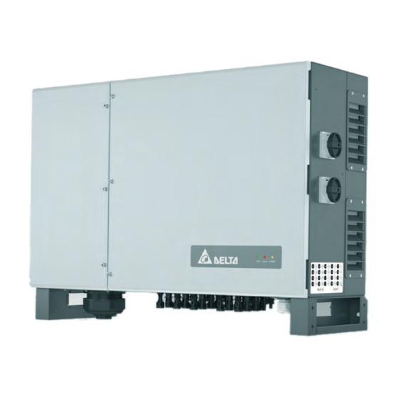
Page 10: Product Overview
For feeding the AC cable into the junction box For fastening the communication cables to the junction box Cable gland for the AC cable gland communication port Installation and operation manual for Solar Power Inverter M125HV EU V1 EN 2019-07-19... - Page 11 Protective cover M6 screws for PE DIN rail cables M4 mounting screw Installation material for DC surge protection devices type 1 PE cable DIN rail M4 mounting screw Installation and operation manual for Solar Power Inverter M125HV EU V1 EN 2019-07-19...
- Page 12 Check the delivery for completeness and all com- ponents for damage before starting installation work. Do not use any damaged components. Keep the packaging. Installation and operation manual for Solar Power Inverter M125HV EU V1 EN 2019-07-19...
-
Page 13: Overview Of Components And Connections
DC Isolating switch 1 DC connector panel, connections 13 to 20 DC Isolating switch 2 DC connector panel, connections 1 to 12 Air inlets with fan modules AC cable gland Installation and operation manual for Solar Power Inverter M125HV EU V1 EN 2019-07-19... - Page 14 15 Integrated DC surge protection device type 2, preliminary 19 AC connection terminals setup for DC surge protection device type 1 included in deliv- 16 Internal fan 1 Installation and operation manual for Solar Power Inverter M125HV EU V1 EN 2019-07-19...
-
Page 15: Leds
Table 4.3.: Meaning of the LED displays on the inverter LED flashes green. LED lights up green. LED flashes red. LED lights up red. Table 4.2.: Meaning of the LED symbols use in this manual Installation and operation manual for Solar Power Inverter M125HV EU V1 EN 2019-07-19... -
Page 16: Ac-Side Components
The optional AC cable feed-through consists of one removable cover and 4 cable glands with several sealing rings for the use of single conductors of different diameters. Installation and operation manual for Solar Power Inverter M125HV EU V1 EN 2019-07-19... -
Page 17: Ac Connection Terminal
Voltage U 895 V Table 4.4.: Specification of the preinstalled AC surge protection devices type 2 Related topics “9.8 Replacing AC surge protection devices type 2”, page 113 Installation and operation manual for Solar Power Inverter M125HV EU V1 EN 2019-07-19... -
Page 18: Preliminary Setup For Ac Surge Protection Devices Type 1
20 pairs of DC plugs are supplied in the scope of delivery. Related topics “5.5 Connecting the solar modules (DC)”, page 42 “6.6 Connecting the grid (AC) and solar modules (DC)”, page Installation and operation manual for Solar Power Inverter M125HV EU V1 EN 2019-07-19... -
Page 19: Dc Isolating Switch
Assignment of the DC isolating switches to the DC strings (symbolic representation) Fig. 4.12: Both DC isolating switches in position OFF = the connection to the solar module is disconnected Installation and operation manual for Solar Power Inverter M125HV EU V1 EN 2019-07-19... -
Page 20: Dc String Fuses
Delta and must be ordered elsewhere. Related topics Related topics “9.9 Replacing DC surge protection devices type 2”, page 117 “9.10 Replacing AC surge protection devices Type 2”, page 121 Installation and operation manual for Solar Power Inverter M125HV EU V1 EN 2019-07-19... -
Page 21: Preliminary Setup For Dc Surge Protection Devices Type 1
1x VCC (12 V, 0,5 A) Terminal block 6x digital inputs Terminal block 2x dry contacts Terminal block 1x external power-off (EPO) Terminal block Table 4.7.: Overview: Connections on the communication card Installation and operation manual for Solar Power Inverter M125HV EU V1 EN 2019-07-19... -
Page 22: Grounding Connection
Available grounding screws: ● 1 x M10 ● 2 x M6 Related topics “5.4 Grid connection (AC)”, page 37 “6.4 Grounding the inverter housing”, page 54 Installation and operation manual for Solar Power Inverter M125HV EU V1 EN 2019-07-19... -
Page 23: Internal Pe Screw
Related topics Related topics “5.4 Grid connection (AC)”, page 37 “6.4 Grounding the inverter housing”, page 54 “9.5 Clean/replace air inlets, air outlets and fan modules”, page Installation and operation manual for Solar Power Inverter M125HV EU V1 EN 2019-07-19... -
Page 24: Internal Fan
View of internal fan 1 with air baffle with cover “9.7 Cleaning/replacing fan 2”, page 107 removed Fig. 4.27: View of internal fan 1 with air baffle removed Installation and operation manual for Solar Power Inverter M125HV EU V1 EN 2019-07-19... -
Page 25: Information On The Type Plate
The inverter can be very loud when in operation. Wear hearing protection when working on or in the vicinity of the inverter. Installation and operation manual for Solar Power Inverter M125HV EU V1 EN 2019-07-19... -
Page 26: Planning The Installation
► When using the inverter in residential areas or in buildings with animals, possible noise emissions can be disturbing. Therefore, carefully choose the place of installation. ► Mount the inverter on a fireproof wall. Installation and operation manual for Solar Power Inverter M125HV EU V1 EN 2019-07-19... -
Page 27: Mounting Alignment
This is normal operating behavior for the inverter and is necessary to protect the internal electronics. Installation and operation manual for Solar Power Inverter M125HV EU V1 EN 2019-07-19... -
Page 28: Mounting Clearances
► In areas with many trees or fields, pollen can clog the air inlets and outlets, hindering the air flow. Installation and operation manual for Solar Power Inverter M125HV EU V1 EN 2019-07-19... -
Page 29: Characteristic Curves
1050 V 1250 V Ambient temperature [°C] Fig. 5.33: Characteristic curve "Active power control depending on the ambient temperature, cos φ = 0.90, AC voltage = 600 V” Installation and operation manual for Solar Power Inverter M125HV EU V1 EN 2019-07-19... - Page 30 1050 V 1250 V Ambient temperature [°C] Fig. 5.34: Characteristic curve "Active power control depending on the ambient temperature, cos φ = 1.00, AC voltage = 600 V" Installation and operation manual for Solar Power Inverter M125HV EU V1 EN 2019-07-19...
- Page 31 1050 V 1250 V Ambient temperature [°C] Fig. 5.35: Characteristic curve "Apparent power control depending on the ambient temperature, cos φ = 0.90, AC voltage = 600 V" Installation and operation manual for Solar Power Inverter M125HV EU V1 EN 2019-07-19...
- Page 32 1250 V 1350 V Ambient temperature [°C] Fig. 5.36: Characteristic curve "Apparent power control depending on the ambient temperature, cos φ = 1.00, AC voltage = 600 V" Installation and operation manual for Solar Power Inverter M125HV EU V1 EN 2019-07-19...
- Page 33 1500 DC Input voltage [ Fig. 5.37: Characteristic curve "Active power control depending on the DC input voltage, cos φ = 0.90, AC voltage = 600 V” Installation and operation manual for Solar Power Inverter M125HV EU V1 EN 2019-07-19...
- Page 34 1500 DC Input voltage [ Fig. 5.38: Characteristic curve "Active power control depending on the DC input voltage, cos φ = 1.00, AC voltage = 600 V” Installation and operation manual for Solar Power Inverter M125HV EU V1 EN 2019-07-19...
- Page 35 Efficiency [%] = 600 V 100% 860 V 1050 V 1250 V 1350 V AC Output power P/P [%]; P = 125 kW Fig. 5.39: Efficiency-characteristic curve Installation and operation manual for Solar Power Inverter M125HV EU V1 EN 2019-07-19...
-
Page 36: Dimensions
5 Planning the installation Dimensions Dimensions Front view with mounting brackets for wall mounting Top view with mounting brackets for floor mounting Dimensions in mm Fig. 5.40: Dimensions Installation and operation manual for Solar Power Inverter M125HV EU V1 EN 2019-07-19... -
Page 37: Grid Connection (Ac)
PV system, and the ambient conditions (e.g. humidity). The tripping current must not, how- ever, be less than the specified minimum tripping current. Installation and operation manual for Solar Power Inverter M125HV EU V1 EN 2019-07-19... -
Page 38: Special Tools Required
712. This standard contains the requirements for minimum cable diameters and for avoiding overheating due to high currents. Always follow the cable lug manufacturer's installation instruc- tions. Permissible dimensions of the cable lugs Installation and operation manual for Solar Power Inverter M125HV EU V1 EN 2019-07-19... -
Page 39: Handling Aluminum Conductors During Installation Work
(= neutral) Vaseline and straight away insert it into the cable lug. ► Tighten the nut on the cable lug with the maximum permissible tightening torque. Installation and operation manual for Solar Power Inverter M125HV EU V1 EN 2019-07-19... -
Page 40: Laying Of The Ac Cable
Fig. 5.42: Recommended feeding of the AC cable with strain relief for floor mounting Fig. 5.41: Recommended feeding of the AC cable with strain relief for wall mounting Installation and operation manual for Solar Power Inverter M125HV EU V1 EN 2019-07-19... -
Page 41: Ac Cable Gland
Germany: Follow the installation instructions of UTE VDE 0100- 712. This standard contains the requirements for minimum cable diameters and for avoiding overheating due to high currents. Installation and operation manual for Solar Power Inverter M125HV EU V1 EN 2019-07-19... -
Page 42: Connecting The Solar Modules (Dc)
DC connections and result in a fire. ► Always take into account the maximum cur- rent of the DC connections when planning the installation. Installation and operation manual for Solar Power Inverter M125HV EU V1 EN 2019-07-19... -
Page 43: Dc Cable Requirements
DC connections on the DC plugs for DC cables inverter DC– Amphenol 4 / 6 5.3 ... 7.65 UTXCFA4A● 4 / 6 5.3 ... 7.65 UTXCMA4A● Included in delivery Installation and operation manual for Solar Power Inverter M125HV EU V1 EN 2019-07-19... -
Page 44: Device Communication And System Monitoring
1x external power-off (EPO) Terminal block Table 5.3.: Overview of connections on the communication card The inverter has 1 cable gland for the communications cable with 2x2 cable feed-throughs. Installation and operation manual for Solar Power Inverter M125HV EU V1 EN 2019-07-19... -
Page 45: Connecting A Data Logger
Maximum active power lim- V1 + K3 ited to 60 % Maximum active power lim- V1 + K4 ited to 100 % V1 + K5 Reserved V1 + K6 Reserved Installation and operation manual for Solar Power Inverter M125HV EU V1 EN 2019-07-19... -
Page 46: External Power-Off
Maximum active power lim- V1 + K3 ited to 60% Maximum active power lim- V1 + K4 ited to 100% V1 + K5 Reserved V1 + K6 Reserved Installation and operation manual for Solar Power Inverter M125HV EU V1 EN 2019-07-19... -
Page 47: Use Of Ac Surge Protection Devices Type 1
The AC surge protection devices type 1 are intended for the assembly of a DIN top-hat rail (always included in the scope of delivery). Fig. 5.43: Dimension limitations for AC surge protection devices type 1 Installation and operation manual for Solar Power Inverter M125HV EU V1 EN 2019-07-19... -
Page 48: Use Of Dc Surge Protection Devices Type 1
The DC surge protection devices type 1 are intended for the assembly of a DIN top-hat rail (always included in the scope of delivery). Fig. 5.44: Dimension limitations for DC surge protection devices type 1 Installation and operation manual for Solar Power Inverter M125HV EU V1 EN 2019-07-19... -
Page 49: Installation
► Disconnect the inverter from all AC and DC voltage sources. Ensure that none of the connections can be restored accidentally. ► Ensure that the DC cables cannot be touched accidentally. Installation and operation manual for Solar Power Inverter M125HV EU V1 EN 2019-07-19... -
Page 50: Sequence Of Work Steps
Attaching warning labels to the inverter “6.7 Attaching warning labels to the inverter”, page 75 Connecting a PC via RS485 “6.8 Connecting a PC via RS485”, page 76 Installation and operation manual for Solar Power Inverter M125HV EU V1 EN 2019-07-19... -
Page 51: Mounting The Inverter
The screws are supplied in the scope of delivery. 2. Fasten the 4 mounting brackets to the floor with 1 M10 screw each. Installation and operation manual for Solar Power Inverter M125HV EU V1 EN 2019-07-19... -
Page 52: Wall Mounting
The screws are supplied in the scope of delivery. 2. Attach the mounting plate to the wall/the mounting system with 6 M10 screws. Installation and operation manual for Solar Power Inverter M125HV EU V1 EN 2019-07-19... - Page 53 4. Check that the inverter is correctly mounted on the mount- ing plate. 5. Attach the mounting plate on the inverter feet to wall/the mounting system with 1 M10 screw each. Installation and operation manual for Solar Power Inverter M125HV EU V1 EN 2019-07-19...
-
Page 54: Grounding The Inverter Housing
Nuts, spring washer and flat washer are mounted on the inverter. Available grounding screws: 1 x M10, torque: 25 Nm 2 x M6, torque: 7 Nm 2. Perform a continuity check of the grounding connection. Installation and operation manual for Solar Power Inverter M125HV EU V1 EN 2019-07-19... -
Page 55: Grounding Via The Pe Screw Of The Ac Connection
Table 6.1.: Permissible cable lug guides for PE connection termi- nals 1. Screw the grounding cable to the PE screw (torque: 25 Nm). M10 screw, spring washer and flat washer are already mounted on the inverter. Installation and operation manual for Solar Power Inverter M125HV EU V1 EN 2019-07-19... - Page 56 6 Installation Grounding the inverter housing 2. Perform a continuity check of the grounding connection. Installation and operation manual for Solar Power Inverter M125HV EU V1 EN 2019-07-19...
-
Page 57: Connecting The Communication Card
Terminal block 6x digital inputs Terminal block 2x dry contacts Terminal block 1x external power-off (EPO) Terminal block Table 6.2.: Overview of connections on the communication card Installation and operation manual for Solar Power Inverter M125HV EU V1 EN 2019-07-19... -
Page 58: Initial Steps
1. Unscrew the cable gland of the communication port and remove the cable gland and seal. 2. Unscrew and carefully pull out the cover. The communica- tion card is screwed onto the cover. Installation and operation manual for Solar Power Inverter M125HV EU V1 EN 2019-07-19... - Page 59 Do not remove the rubber plugs from the unused seal feed-throughs. 4. Pull the cable through the cable gland and seal. Installation and operation manual for Solar Power Inverter M125HV EU V1 EN 2019-07-19...
-
Page 60: Connecting A Data Logger Via Rs485
Data format Baud rate 9600, 19200, 38400; standard: 19200 Data bits Stop bit Parity Not applicable Data logger Fig. 6.3: RS485: Wiring diagram for a single inverter Installation and operation manual for Solar Power Inverter M125HV EU V1 EN 2019-07-19... - Page 61 Termination resistor = ON Termination resistor = OFF Termination resistor = OFF RS485 Data logger Fig. 6.4: RS485: Wiring diagram for multiple inverters Installation and operation manual for Solar Power Inverter M125HV EU V1 EN 2019-07-19...
- Page 62 1. Connect the DATA+ wire to terminal 5 and the DATA– wire to terminal 6. 2. Set the DIP switch for the RS485 termination resistor (DIP 2) to the ON position. Installation and operation manual for Solar Power Inverter M125HV EU V1 EN 2019-07-19...
- Page 63 DATA+ wire to terminal 3 and the DATA– wire to terminal 2. Set the DIP switch for the RS485 termination resistor (DIP 2) to the OFF position. Installation and operation manual for Solar Power Inverter M125HV EU V1 EN 2019-07-19...
- Page 64 DATA+ wire to terminal 3 and the DATA– wire to terminal 4. Set the DIP switch for the RS485 termination resistor (DIP 2) to the OFF position. Installation and operation manual for Solar Power Inverter M125HV EU V1 EN 2019-07-19...
- Page 65 5. Connect the DATA+ wire to terminal 5 and the DATA– wire to terminal 6. 6. Set the DIP switch for the RS485 termination resistor (DIP 2) to the ON position. Installation and operation manual for Solar Power Inverter M125HV EU V1 EN 2019-07-19...
-
Page 66: Connecting An External Alarm Unit
1. Connect two wires of the cable to one of the two dry contacts. 2. After commissioning, use the Delta Service Software to as- sign an event for triggering the alarm unit. Installation and operation manual for Solar Power Inverter M125HV EU V1 EN 2019-07-19... - Page 67 1. Connect the wires according to the desired connection diagram. 2. An event can be assigned to the dry contacts with the Delta Service Software after commissioning. Installation and operation manual for Solar Power Inverter M125HV EU V1 EN 2019-07-19...
- Page 68 1. Connect the wires according to the desired connection diagram. 2. An event can be assigned to the dry contacts with the Delta Service Software after commissioning. Installation and operation manual for Solar Power Inverter M125HV EU V1 EN 2019-07-19...
-
Page 69: Connecting A Ripple Control Receiver
CAT5 cable and may differ in other cables. The wire colors have no effect on the function of the wiring. ► Connect the wires according to the desired connection diagram. Installation and operation manual for Solar Power Inverter M125HV EU V1 EN 2019-07-19... -
Page 70: Connecting The External Power-Off (Epo)
1. Connect the wires to the terminals V1 and K0. 2. After commissioning, the relay for the external power-off can be defined with the Delta Service Software as normally closed or normally open relays. Installation and operation manual for Solar Power Inverter M125HV EU V1 EN 2019-07-19... -
Page 71: Final Work
1. Insert the communication card and screw it in place. 2. Insert the seal and cable gland of the communication port and screw the cable gland in place. Installation and operation manual for Solar Power Inverter M125HV EU V1 EN 2019-07-19... -
Page 72: Connecting The Grid (Ac) And Solar Modules (Dc)
∅ 58,2 ... 65,1 mm ∅ 65,1 ... 72,5 mm ∅ 72,5 ... 76,8 mm Fig. 6.12: Use of the parts of the AC cable glands depends on the cable diameter Installation and operation manual for Solar Power Inverter M125HV EU V1 EN 2019-07-19... - Page 73 4. Screw on the cover of the AC connection (torque: 0.8 Nm). 5. Fit the conductor of the AC cable and screw it into place (torque: 25 Nm). Installation and operation manual for Solar Power Inverter M125HV EU V1 EN 2019-07-19...
- Page 74 NOTE: Do not skew the doors and screws! 7. Plug in the DC cables. 8. Turn both DC isolating switches to the ON position. → The inverter starts a self-test lasting approx. 2 minutes. Installation and operation manual for Solar Power Inverter M125HV EU V1 EN 2019-07-19...
-
Page 75: Attaching Warning Labels To The Inverter
Warning - Only persons authorized by DNO may remove the main cut out fuse Warning Two voltage sources present Prior to any work, disconnect - Distribution network both sources - PV modules Fig. 6.13: Examples of warning labels Installation and operation manual for Solar Power Inverter M125HV EU V1 EN 2019-07-19... -
Page 76: Connecting A Pc Via Rs485
6 Installation Connecting a PC via RS485 Connecting a PC via RS485 Inverter USB/RS485 adapter DATA+ Terminal 3 or 5 DATA– Terminal 4 or 6 D– Installation and operation manual for Solar Power Inverter M125HV EU V1 EN 2019-07-19... -
Page 77: Commissioning
→ A list of the inverters found is shown. Each inverter is automatically assigned an inverter ID (1). → See “7.3 Troubleshooting during commissioning”, page 80 if an error mes- sage appears. Installation and operation manual for Solar Power Inverter M125HV EU V1 EN 2019-07-19... - Page 78 80 if an error mes- sage appears. 7. To set the date and time for all inverters, click on the Sync time button (1). Installation and operation manual for Solar Power Inverter M125HV EU V1 EN 2019-07-19...
- Page 79 7 Commissioning Commissioning steps with the commissioning software → The message “Sync Time successful” appears if the setting was successful. þ Commissioning is now finished. Installation and operation manual for Solar Power Inverter M125HV EU V1 EN 2019-07-19...
-
Page 80: Troubleshooting During Commissioning
► To finish, click on the Scan Fewer inverters were found when scanning the RS485 ring than specified in the Inv num Inverters button (2). text box. Installation and operation manual for Solar Power Inverter M125HV EU V1 EN 2019-07-19... - Page 81 ► Check the time on the PC. “Time Sync failed.” ► To finish, click on the Sync time button (1). (German: “Synchronisierung der Uhrzeit fehlgeschlagen.”) Cause of error Time synchronization failed. Installation and operation manual for Solar Power Inverter M125HV EU V1 EN 2019-07-19...
-
Page 82: Error Events And Troubleshooting
► Do not open the doors if water or dirt might enter the inverter. ► After work is completed, ensure that the doors are properly shut and screwed in again. Check that the doors are properly sealed. Installation and operation manual for Solar Power Inverter M125HV EU V1 EN 2019-07-19... -
Page 83: Error
Check the insulation of the DC inputs. Insulation Large PV system capacitance between Plus Check the capacity. Dry the PV modules if nec- and Ground or Minus and Ground or both. essary. Installation and operation manual for Solar Power Inverter M125HV EU V1 EN 2019-07-19... -
Page 84: Warnings
One or more surge protection devices are Replace the defective surge protection devices. defective. AC Surge One or more surge protection devices are incor- Check all surge protection devices. rectly fitted. Installation and operation manual for Solar Power Inverter M125HV EU V1 EN 2019-07-19... -
Page 85: Faults
DC input voltage. permissible DC input voltage. F31, F33, HW Bus OVR Overvoltage during operation. Contact Delta Customer Service. Internal error. Contact Delta Customer Service. Installation and operation manual for Solar Power Inverter M125HV EU V1 EN 2019-07-19... - Page 86 Internal error. Contact Delta Customer Service. Internal error. Contact Delta Customer Service. HW ZC Fail F60, F61, Internal error. Contact Delta Customer Service. DC Current High F70, F71 Installation and operation manual for Solar Power Inverter M125HV EU V1 EN 2019-07-19...
-
Page 87: Maintenance
► Do not open the doors if water or dirt might enter the inverter. ► After work is completed, ensure that the doors are properly shut and screwed in again. Check that the doors are properly sealed. Installation and operation manual for Solar Power Inverter M125HV EU V1 EN 2019-07-19... -
Page 88: Periodic Maintenance
AC surge protection devices type 2 ● DC surge protection devices type 2 ● AC surge protection devices type 1 (if used) ● DC surge protection devices type 1 (if used) Installation and operation manual for Solar Power Inverter M125HV EU V1 EN 2019-07-19... -
Page 89: Making Preparations For Maintenance Work - Disconnecting The Inverter From The Mains (Ac) And Solar Modules (Dc)
1. To shut off the inverter's grid voltage, open the load isolat- ing switch between the inverter and the mains connection point. Secure the load isolating switch to prevent it from acciden- tally being switched back on. Installation and operation manual for Solar Power Inverter M125HV EU V1 EN 2019-07-19... - Page 90 2. Turn both DC isolating switches to the OFF position. 3. Wait at least 135 seconds until the internal capacitors have discharged. 4. Unscrew the left door with one of the supplied Allen wrenches. Installation and operation manual for Solar Power Inverter M125HV EU V1 EN 2019-07-19...
- Page 91 5. Secure the left door with the Allen wrench. 6. Unscrew the right door with another supplied Allen wrench. 7. Secure the right door with the Allen wrench. Installation and operation manual for Solar Power Inverter M125HV EU V1 EN 2019-07-19...
- Page 92 OFF position. → If you detect no voltage, proceed to the next step. 10. Use the mounting tool to release the DC cables and then pull them out. Installation and operation manual for Solar Power Inverter M125HV EU V1 EN 2019-07-19...
- Page 93 11. Unscrew and remove the conductor of the AC cable. 12. Unscrew the cover of the AC cable feed-through and re- move the cable together with the cover and the AC cable gland. Installation and operation manual for Solar Power Inverter M125HV EU V1 EN 2019-07-19...
-
Page 94: Clean/Replace Air Inlets, Air Outlets And Fan Modules
There are two air outlets with replaceable fan modules on the right side of the inverter. There are two air outlets on the left side of the inverter. Installation and operation manual for Solar Power Inverter M125HV EU V1 EN 2019-07-19... -
Page 95: Clean Air Inlets And Clean/Replace Fan Modules
This procedure is the same for both fan modules. The fan modules are replaced as a block. ∫ 1. Unscrew the air filter and remove it. 2. Unscrew the fan module and carefully pull out. Installation and operation manual for Solar Power Inverter M125HV EU V1 EN 2019-07-19... - Page 96 Clean/replace air inlets, air outlets and fan modules 3. Pull out the plugs of the 2 power supply cables. 4. Clean the air filter with a compressed air cleaner or a stiff paintbrush. Installation and operation manual for Solar Power Inverter M125HV EU V1 EN 2019-07-19...
- Page 97 It doesn’t matter which power supply cable you use for which fan. 7. Insert the fan modules so that the power supply cables are on the left side, and tighten them. Installation and operation manual for Solar Power Inverter M125HV EU V1 EN 2019-07-19...
- Page 98 10 Maintenance Clean/replace air inlets, air outlets and fan modules 8. Insert the air filter so that the ridges point downwards, and tighten. Installation and operation manual for Solar Power Inverter M125HV EU V1 EN 2019-07-19...
-
Page 99: Cleaning The Air Outlets
This procedure is the same for both air outlets. ∫ 9. Unscrew the air filter and remove it. 10. Clean the air filter with a compressed air cleaner or a stiff paintbrush. Installation and operation manual for Solar Power Inverter M125HV EU V1 EN 2019-07-19... - Page 100 12. To complete the maintenance work, follow the instructions in the following section: “9.11 Finishing the maintenance work - connecting the inverter to the mains (AC) and solar modules (DC)”, page 125. Installation and operation manual for Solar Power Inverter M125HV EU V1 EN 2019-07-19...
-
Page 101: Cleaning/Replacing Fan 1
You should there- fore use a magnetic screwdriver. ∫ 1. Remove the cover of the DC surge protection device. 2. Unscrew the air baffle and remove it. Installation and operation manual for Solar Power Inverter M125HV EU V1 EN 2019-07-19... - Page 102 10 Maintenance Cleaning/replacing fan 1 3. Disconnect the fan's power supply cable. 4. Unscrew the metal housing with the screwed-in fan and pull it out carefully. Installation and operation manual for Solar Power Inverter M125HV EU V1 EN 2019-07-19...
- Page 103 ∫ 5. Unscrew and remove the fan from the metal housing. 6. Clean the fans and metal housing with a compressed air cleaner or a stiff paintbrush. Installation and operation manual for Solar Power Inverter M125HV EU V1 EN 2019-07-19...
- Page 104 7. Insert the fan in the metal housing and screw it in place. 8. Insert the metal housing with the screwed-in fan carefully and screw it in place. Installation and operation manual for Solar Power Inverter M125HV EU V1 EN 2019-07-19...
- Page 105 9. Plug in the fan's power supply cable. 10. Insert the air baffle and screw it in place. 11. Insert the cover of the DC surge protection device. Installation and operation manual for Solar Power Inverter M125HV EU V1 EN 2019-07-19...
- Page 106 12. To complete the maintenance work, follow the instructions in the following section: “9.11 Finishing the maintenance work - connecting the inverter to the mains (AC) and solar modules (DC)”, page 125. Installation and operation manual for Solar Power Inverter M125HV EU V1 EN 2019-07-19...
-
Page 107: Cleaning/Replacing Fan 2
∫ 1. Unscrew and remove the AC surge protection devices. Installation and operation manual for Solar Power Inverter M125HV EU V1 EN 2019-07-19... - Page 108 2. Unscrew the metal housing with the screwed-in fan and carefully remove a piece until the plug of the power supply is accessible. 3. Disconnect the fan's power supply cable. Installation and operation manual for Solar Power Inverter M125HV EU V1 EN 2019-07-19...
- Page 109 ∫ 4. Unscrew and remove the fan from the metal housing. 5. Clean the fan with a compressed air cleaner or a stiff paintbrush. Installation and operation manual for Solar Power Inverter M125HV EU V1 EN 2019-07-19...
- Page 110 6. Insert the fan in the metal housing and screw it in place. 7. Insert the metal housing with the screwed-in fan carefully, but do not yet screw it in place. 8. Plug in the fan's power supply cable. Installation and operation manual for Solar Power Inverter M125HV EU V1 EN 2019-07-19...
- Page 111 9. Screw in the metal housing with the screwed-in fan. 10. Fit the cover of the AC surge protection devices and screw it into place (torque: 0.8 Nm). Installation and operation manual for Solar Power Inverter M125HV EU V1 EN 2019-07-19...
- Page 112 11. To complete the maintenance work, follow the instructions in the following section: “9.11 Finishing the maintenance work - connecting the inverter to the mains (AC) and solar modules (DC)”, page 125. Installation and operation manual for Solar Power Inverter M125HV EU V1 EN 2019-07-19...
-
Page 113: Replacing Ac Surge Protection Devices Type 2
1. Unscrew and remove the AC surge protection devices. 2. Unscrew and remove the power supply cable of the AC surge protection devices. Installation and operation manual for Solar Power Inverter M125HV EU V1 EN 2019-07-19... - Page 114 10 Maintenance Replacing AC surge protection devices type 2 3. Pull out the signal cable plug. 4. Unscrew and remove card with the AC surge protection devices. Installation and operation manual for Solar Power Inverter M125HV EU V1 EN 2019-07-19...
- Page 115 Replacing AC surge protection devices type 2 5. Unscrew and remove the card with the new AC surge protection devices. 6. Plug in the signal cable plug. 7. Tighten the power supply cable. Installation and operation manual for Solar Power Inverter M125HV EU V1 EN 2019-07-19...
- Page 116 9. To complete the maintenance work, follow the instructions in the following section: “9.11 Finishing the maintenance work - connecting the inverter to the mains (AC) and solar modules (DC)”, page 125. Installation and operation manual for Solar Power Inverter M125HV EU V1 EN 2019-07-19...
-
Page 117: Replacing Dc Surge Protection Devices Type 2
∫ 1. Remove the cover of the DC surge protection device. 2. Unscrew and remove the power supply cables of the DC surge protection devices. Installation and operation manual for Solar Power Inverter M125HV EU V1 EN 2019-07-19... - Page 118 Replacing DC surge protection devices type 2 3. Pull out the signal cable plug and remove it. 4. Unscrew and remove card with the DC surge protection devices. Installation and operation manual for Solar Power Inverter M125HV EU V1 EN 2019-07-19...
- Page 119 Replacing DC surge protection devices type 2 5. Unscrew and remove the card with the new DC surge protection devices. 6. Plug in the signal cable plug and screw on. Installation and operation manual for Solar Power Inverter M125HV EU V1 EN 2019-07-19...
- Page 120 9. To complete the maintenance work, follow the instructions in the following section: “9.11 Finishing the maintenance work - connecting the inverter to the mains (AC) and solar modules (DC)”, page 125. Installation and operation manual for Solar Power Inverter M125HV EU V1 EN 2019-07-19...
-
Page 121: Replacing Ac Surge Protection Devices Type 2
You should therefore use a magnetic screwdriver. ∫ 1. Unscrew and remove the cover of the AC surge protection devices Type 2. Installation and operation manual for Solar Power Inverter M125HV EU V1 EN 2019-07-19... - Page 122 2. Unscrew and remove the power supply cable of the AC surge protection devices Type 2. 3. Pull out the signal cable plug. 4. Unscrew and remove card with the AC surge protection devices Type 2. Installation and operation manual for Solar Power Inverter M125HV EU V1 EN 2019-07-19...
- Page 123 10 Maintenance Replacing AC surge protection devices Type 2 5. Unscrew and remove the card with the new AC surge protection devices. 6. Insert the signal cable plug. Installation and operation manual for Solar Power Inverter M125HV EU V1 EN 2019-07-19...
- Page 124 10 Maintenance Replacing AC surge protection devices Type 2 7. Fit the AC surge protection device type 2 cover and screw it into place. Installation and operation manual for Solar Power Inverter M125HV EU V1 EN 2019-07-19...
-
Page 125: Finishing The Maintenance Work - Connecting The Inverter To The Mains (Ac) And Solar Modules (Dc)
2. Screw on the cover of the AC cable gland (torque: 0.8 Nm). 3. Insert and screw on the conductor of the AC cable and screw it into place (torque: 25 Nm). Installation and operation manual for Solar Power Inverter M125HV EU V1 EN 2019-07-19... - Page 126 4. Seal both doors and tighten with a torque Allen wrench (torque: 4.4 Nm). NOTE: Do not skew the doors and screws! 5. Plug in the DC cables. Installation and operation manual for Solar Power Inverter M125HV EU V1 EN 2019-07-19...
- Page 127 7. Turn both DC isolating switches to the ON position. → The inverter starts a self-test lasting approx. 2 minutes. Installation and operation manual for Solar Power Inverter M125HV EU V1 EN 2019-07-19...
-
Page 128: Replacing The Inverter
Stable, clean and dry storage surface, for example a table, doors are properly shut and screwed in on which the two inverters can be placed. again. Check that the doors are properly sealed. Installation and operation manual for Solar Power Inverter M125HV EU V1 EN 2019-07-19... - Page 129 3. Turn both DC isolating switches to the OFF position. 4. Wait at least 135 seconds until the internal capacitors have discharged. Installation and operation manual for Solar Power Inverter M125HV EU V1 EN 2019-07-19...
- Page 130 5. Unscrew the left door with one of the supplied Allen wrenches. 6. Secure the left door with the Allen wrench. 7. Unscrew the right door with another supplied Allen wrench. Installation and operation manual for Solar Power Inverter M125HV EU V1 EN 2019-07-19...
- Page 131 → When voltage is applied, check that both DC isolating switches are in the OFF position. → If you detect no voltage, proceed to the next step. Installation and operation manual for Solar Power Inverter M125HV EU V1 EN 2019-07-19...
- Page 132 12. Remove the cover caps for the DC connections from the replacement unit and plug them into the DC connections of the old inverter. 13. Unscrew and remove the conductor of the AC cable. Installation and operation manual for Solar Power Inverter M125HV EU V1 EN 2019-07-19...
- Page 133 AC cable gland. 15. Unscrew the cover of the AC cable gland including the AC cable gland from the replacement unit and screw it onto the old inverter. Installation and operation manual for Solar Power Inverter M125HV EU V1 EN 2019-07-19...
- Page 134 Insert everything into the old inverter and screw in place. 18. Lock both doors on the old inverter and screw them shut. Installation and operation manual for Solar Power Inverter M125HV EU V1 EN 2019-07-19...
- Page 135 20. Secure the inverter with a block and tackle or with crane so that the weight will be suspended from the block and tackle after the mounting screws are loosened. Installation and operation manual for Solar Power Inverter M125HV EU V1 EN 2019-07-19...
- Page 136 11 Replacing the inverter 21. Unscrew the grounding cable from the inverter. 22. Unscrew the mounting brackets on the feet of the inverter. Installation and operation manual for Solar Power Inverter M125HV EU V1 EN 2019-07-19...
- Page 137 25. Pack and ship the old inverter according to the comments you received from Delta Customer Service. 26. Install and commission the new inverter according to the supplied installation manual. Installation and operation manual for Solar Power Inverter M125HV EU V1 EN 2019-07-19...
-
Page 138: Installing Accessories
► Do not open the doors if water or dirt might enter the inverter. ► After work is completed, ensure that the doors are properly shut and screwed in again. Check that the doors are properly sealed. Installation and operation manual for Solar Power Inverter M125HV EU V1 EN 2019-07-19... -
Page 139: Making Preparations For Work - Disconnecting The Inverter From The Mains (Ac) And Solar Modules (Dc)
1. To shut off the inverter's grid voltage, open the load isolat- ing switch between the inverter and the mains connection point. Secure the load isolating switch to prevent it from acciden- tally being switched back on. Installation and operation manual for Solar Power Inverter M125HV EU V1 EN 2019-07-19... - Page 140 2. Turn both DC isolating switches to the OFF position. 3. Wait at least 135 seconds until the internal capacitors have discharged. 4. Unscrew the left door with one of the supplied Allen wrenches. Installation and operation manual for Solar Power Inverter M125HV EU V1 EN 2019-07-19...
- Page 141 5. Secure the left door with the Allen wrench. 6. Unscrew the right door with another supplied Allen wrench. 7. Secure the right door with the Allen wrench. Installation and operation manual for Solar Power Inverter M125HV EU V1 EN 2019-07-19...
- Page 142 OFF position. → If you detect no voltage, proceed to the next step. 10. Use the mounting tool to release the DC cables and then pull them out. Installation and operation manual for Solar Power Inverter M125HV EU V1 EN 2019-07-19...
- Page 143 11. Unscrew and remove the conductor of the AC cable. 12. Unscrew the cover of the AC cable feed-through and re- move the cable together with the cover and the AC cable gland. Installation and operation manual for Solar Power Inverter M125HV EU V1 EN 2019-07-19...
-
Page 144: Installing Ac Surge Protection Devices Type 1
1. Connect the power cable, signal cable and PE cable to the Stromkabel AC surge protection devices type 1 in accordance with the Câble de l’alimentation two figures on the left. PE-Kabel Câble PE Câble de signalisation Signalkabel Installation and operation manual for Solar Power Inverter M125HV EU V1 EN 2019-07-19... -
Page 145: Mounting And Connecting The Ac Surge Protection Devices
2. Unscrew and remove the power supply cables from the AC surge protection devices type 2. Store the power supply cables for later reuse and tape them to the inside of the left door, for example. Installation and operation manual for Solar Power Inverter M125HV EU V1 EN 2019-07-19... - Page 146 4. Pull the plug with the PCB cable from the socket for the AC surge protection devices type 2 and plug into the socket for the AC surge protection devices type 1. Installation and operation manual for Solar Power Inverter M125HV EU V1 EN 2019-07-19...
- Page 147 9 Installing accessories Installing AC surge protection devices type 1 5. Unscrew and remove the AC surge protection devices type 1. Installation and operation manual for Solar Power Inverter M125HV EU V1 EN 2019-07-19...
- Page 148 7. Insert the cover of the AC surge protection devices type 1. 8. Screw the DIN top-hat rail with the AC surge protection devices type 1 and the cover tight. Installation and operation manual for Solar Power Inverter M125HV EU V1 EN 2019-07-19...
- Page 149 9. Screw the PE cable on the DIN top-hat rail tight. 10. Insert the plug with the signal cable into the socket for the AC surge protection devices type 1. Installation and operation manual for Solar Power Inverter M125HV EU V1 EN 2019-07-19...
- Page 150 AC surge protection devices type 1. The wiring should now look like this. 12. Fit the AC surge protection device type 2 cover and screw it into place. Installation and operation manual for Solar Power Inverter M125HV EU V1 EN 2019-07-19...
- Page 151 13. To complete the installation work, follow the instructions in the following section: “11.4 Finishing the work - connecting the inverter to the mains (AC) and solar modules (DC)”, page 152. Installation and operation manual for Solar Power Inverter M125HV EU V1 EN 2019-07-19...
-
Page 152: Finishing The Work - Connecting The Inverter To The Mains (Ac) And Solar Modules (Dc)
15. Screw on the cover of the AC cable feed-through (torque: 0.8 Nm). 16. Fit the conductor of the AC cable and screw it into place (torque: 25 Nm). Installation and operation manual for Solar Power Inverter M125HV EU V1 EN 2019-07-19... - Page 153 17. Seal both doors and tighten with a torque Allen wrench (torque: 4.4 Nm). NOTE: Do not skew the doors and screws! 18. Plug in the DC cables. Installation and operation manual for Solar Power Inverter M125HV EU V1 EN 2019-07-19...
- Page 154 20. Turn both DC isolating switches to the ON position. → The inverter starts a self-test lasting approx. 2 minutes. Installation and operation manual for Solar Power Inverter M125HV EU V1 EN 2019-07-19...
- Page 155 Installation and operation manual for Solar Power Inverter M125HV EU V1 EN 2019-07-19...
-
Page 156: Technical Data
<3% at rated apparent power DC injection <0.5% at nominal current Power loss in night mode <3.5 W Overvoltage category Surge protection devices Type 2, replaceable (type 1 upgradeable) Installation and operation manual for Solar Power Inverter M125HV EU V1 EN 2019-07-19... - Page 157 IEC 60664-1, IEC 62109-1 EN 50539-11 For cos phi = 1 (VA = W) AC voltage and frequency range are programmed using the corresponding country specifications. EN 61463-11 Installation and operation manual for Solar Power Inverter M125HV EU V1 EN 2019-07-19...
- Page 158 +49 7641 455 549 © Copyright – Delta Energy Systems (Germany) GmbH – All rights reserved. All information and specifications can be modified without prior notice. Installation and operation manual for Solar Power Inverter M125HV EU V1 EN 2019-07-19...