Table of Contents
Advertisement
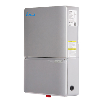
TL-US | M5-TL-US | M6-TL-US | M8-TL-US | M10-TL-US
Features:
Operation and Installation Manual for M Series
mart inverter with Bluetooth, optional WiFi, Zigbee, 3G/4G
ellular communication
M4-TL-US
ield upgrade-able from solar inverter (M6, M8) to storage system
M5-TL-US
M6-TL-US
y adding battery pack and software upgrade
M8-TL-US
M10-TL-US
upporting bi-directional cloud communication & monitoring
ype 4 protection with natural convection cooling
uilt-in AFCI & Rapid shutdown controller
US
o field commissioning required
EC efficiency 97.5%
Advertisement
Table of Contents

Related Manuals for Delta M Series


Summary of Contents for Delta M Series
- Page 1 TL-US | M5-TL-US | M6-TL-US | M8-TL-US | M10-TL-US Features: Operation and Installation Manual for M Series mart inverter with Bluetooth, optional WiFi, Zigbee, 3G/4G ellular communication M4-TL-US ield upgrade-able from solar inverter (M6, M8) to storage system M5-TL-US ...
- Page 3 This manual accompanies our equipment for use by the end users. The technical instructions and illustrations contained in this ma- nual are to be treated as confidential and no part may be reproduced without the prior written permission of DELTA ELECTRONICS (SHANGHAI) CO.,LTD.
-
Page 4: Table Of Contents
Equipment overview Inverter type and safety labels Installation Visual inspection Installation location Mounting the inverter Required torques for M series NA solar inverters Electrical connections General safety Utility AC voltage AC circuit breaker requirements Grounding electrode conductor (GET) Lightning and surge protection... - Page 5 5.1.2 LED Status 5.1.3 LED Message Button 5.2.1 Reset button Inverter turn-on procedure Inverter turn-off procedurel M Series APP(Android) Manual 5.5.1 Introduction 5.5.2 Installation 5.5.3 Connection 5.5.4 Functions Production information Repair Decommissioning, transport, storage, disposal Decommissioning Packaging Transport Storage Dispose...
-
Page 6: General Safety Instructions
Cependant, comme pour tous les équipements électriques et électroniques, des mesures de sécurité doivent être respectées et observées durant l’installation et l’exploitation des onduleurs M series de Delta afin de réduire le risque de préjudice corporel et de garantir la sécurité de l’installation. -
Page 7: Safety Symbols And Terminology Definitions
Lisez l’intégralité du manuel et prenez note de toutes les déclarations relatives à la sécurité sous les rubriques intitulées DANGER ! AVERTISSEMENT ! PRUDENCE ! et AVIS ! avant de commencer l’installation ou la mise en service des onduleurs solaires M4-TL-US,M5-TL-US,M6-TL-US, M8-TL- US ,and M10-TL-US. -
Page 8: Safety Instructions
The inverter section contains no user-serviceable parts. For all service and maintenance, the inverter should be returned to a Delta Authorized Service Center. • Read all of these instructions, cautions, and warnings for the Delta M series inverter and associated PV array documentation. •... -
Page 9: Introduction
UL 1741 SA for Grid Support Utility Interactive Inverters that support a more stable utility grid. Delta SOLIVIA TL series were testing to the UL 1741 SA for CA Rule 21 and other Source Requirement Document (SRD) including ‘PG&E Electric Rule No.21 Hh’ Jul,2017, ‘SCE Rule21 Hh’, ‘SDGE Rule21 Hh’... -
Page 10: System
System The content of renewable energy with respect to overall power consumption worldwide is increas- ing annually by approximately 25%. The reason for this rise can be primarily attributed to the con- stantly increasing demand for power, the increasing interest in environmentally friendly technolo- gies, as well as the increasing costs of non-renewable energy. -
Page 11: Technical Structure Of The Solar Inverter
The high-quality aluminum casing corresponds to protection degree NEMA 4 (NEMA 3R for wiring box) and is protected by an anti-corrosion finish. The heat sink on the M series inverters is designed in such a way that operation of the inverter is possible at ambient temperatures from -22°F to +113°F (-30°C to +45°C) at full power and optimal efficiency for either 240 Vac or 208 Vac... -
Page 12: Ambient Temperature
5000 Voc* 4000 range *Voc:range of open circuit 3000 2000 1000 Figure 1: Typical derating curve of M series solar inverter PV input(V) 480V 270V 550V 120V Solar inverter PV input DC voltage range 6000 Pac(W) M5-TL-US 4800W... -
Page 13: Efficiency
9000 Pac(W) 8000 M8-TL-US 7680W 7000 5760W M6-TL-US 6000 non-operating range 5000 Voc* 4000 range *Voc:range of open circuit 3000 2000 1000 PV input(V) 480V 270V 550V 120V Figure 3: M6-TL-US / M8-TL-US DC voltage range 6000 Pac(W) M5-TL-US 4800W 5000 12000 Pac(W) - Page 14 97.5 CEC Efficiency = 97.5% 200 Vdc 380 Vdc 480 Vdc 200 Vdc 380 Vdc Manufacturer: Delta Electronics (Shanghai) Co., Ltd. HangZhou Branch 480 Vdc Model #: Mario 8k 100% Rated Maximum Continuous Output Power: 7.68 kW Night Tare Loss:...
-
Page 15: Equipment Overview
Vmin 97.5 95.46 97.04 97.54 97.77 97.61 97.26 Vnom 97.8 96.36 97.61 98.01 98.08 97.83 97.50 Vmax 97.5 95.13 96.87 97.50 97.81 97.65 97.36 CEC Efficiency = 97.5% 300 Vdc 380 Vdc 480 Vdc 300 Vdc 380 Vdc 480 Vdc % of Rated Output Power Figure 7: M10-TL-US efficiency plot Equipment overview... - Page 16 A further description of the equipment features: (1) Solar Inverter Power Box - This is the inverter section of the assembly. This section is sealed at the factory and there are no user-serviceable parts inside. All wiring to install the inverter is done in the wiring box.
-
Page 17: Inverter Type And Safety Labels
DRAWN: DESIGN: Brighton APPROVE: DATE: DIMENSIONAL TOLERANCES THESE DRAWINGS AND SPECIFICATIONS ARE THE PROPERTY OF ( V ) DELTA ELECTRONICS, INC. AND SHALL NOT BE REPRODUCED OR DECIMALS <50 :±0.1 <50 :±0.15 <50 :±0. USED AS THE BASIS FOR THE MANUFACTURE OR SELL OF :±0.3... - Page 18 Figure 10: Dimensions of M Series inverters Figure 11: Wiring box of M series inverters (1) BAT Fuse Holders (5) AC side L1 (2) RS485 Termination (6) AC side Netural (3) PV terminals (7) AC side L2 (4) Grounding (8) RS485 communication ports...
-
Page 19: Installation
M series inverter and associated PV array documentation. AVERTISSEMENT! Lisez toutes les instructions, rubriques Prudence et Avertissement de l’onduleur Delta M series , ainsi que la documentation sur le panneau photovoltaïque associé. Installation and commissioning must be performed by a licensed... - Page 20 These servicing instructions are for use by qualified personnel only. WARNING! To reduce the risk of electric shock, refer all servicing to factory qualified service personnel. No user service parts are contained AVERTISSEMENT! inside the inverter. Les instructions concernant la maintenance sont destinées à être utilisées uniquement par un personnel qualifié.
-
Page 21: Visual Inspection
Mounting plate c. Operation and installation manual Visually inspect the Delta M series inverter for any physical damage such as a bent heatsink fin and dented chassis. If the inverter appears to be damaged or if the inverter needs to be returned, please contact your local Delta representative. -
Page 22: Mounting The Inverter
Mounting the inverter Please make sure the inverter is installed vertically, especially if it is to be installed outdoors. Inverter should be at least >20" 20“ (50.8 cm) from any (50.8 cm) ceiling surface >4" >6" >6" (10 cm) (15.2 cm) (15.2 cm) Inverter should be mounted >39"... - Page 23 5.91in (150mm) 4.72in (120mm) Figure 13: Dimension drawing of mounting plate 9.45in (240mm) Mount the mounting plate to the wall with at least 4 screws and anchors (Ø 6mm). With 4 screws use 4 holes A or 4 holes B (see Figure 14). You can use the mounting plate as a template for marking the positions of the boreholes.
-
Page 24: Required Torques For M Series Na Solar Inverters
Wiring Box Interior M5 screws (T25 head x4) that secure the max. 35 in-lbs (4 Nm) Screws wiring box to the inverter stage assembly Table 2: Required Torques for M series NA solar inverters... -
Page 25: Electrical Connections
M series inverter and associated PV array documentation. AVERTISSEMENT! Lisez toutes les instructions, rubriques Prudence et Avertissement de l’onduleur Delta M series , ainsi que la documentation sur le panneau photovoltaïque associé. Installation and commissioning must be performed by a licensed... -
Page 26: Utility Ac Voltage
Utility AC voltage The Delta M series inverters are grid-tied to the public utility. Delta NA inverters are software con- figurable via the user display panel for various 208 Vac or 240 Vac 60 Hz public utility grid as shown in figures 16-22. - Page 27 Figure 17: 208V / 120V WYE AC Grid Figure 18: 240V Delta AC Grid Figure 19: 240V / 120V Stinger AC Grid Public Grid Configurations NOT Allowed: Figure 20: 480V Delta AC Grid Figure 21: 480V / 277V WYE AC Grid...
-
Page 28: Ac Circuit Breaker Requirements
AC circuit breaker requirements A dedicated circuit breaker in the building circuit panel is required for each Delta M series inver- ter that is installed. There should be a circuit breaker or fuse to protect each AC line, L1 and L2. -
Page 29: Pv String Considerations
PV string considerations There are a large number of PV module string combinations that will offer optimal performance from either the M4-TL-US,M5-TL-US,M6-TL-US,M8-TL-US and M10-TL-US inverters thanks to its wide full power MPP range (50 V – 48 0 V) Follow the temperature multiplication factors given in NEC 690.7 INFORMATION! table and the PV module manufacturer specified V/Temp coeffici- ent to ensure PV string voltage is less than <... - Page 30 Ensure no live voltages are present on PV input and AC output WARNING! circuits, and verify that the DC disconnect, AC disconnect, and de- AVERTISSEMENT! dicated AC branch circuit breaker are in the “OFF” position, before inverter installation. Assurez-vous qu’aucune tension directe n’est présente sur les circuits photovoltaïques d’entrée et de sortie du CA, vérifiez que le CC et le CA sont déconnectés, et que le disjoncteur de dérivation dédié...
- Page 31 Grid DC Power AC Power Communication Customer Cloud Figure 22: M series Inverter electrical diagram POWER FED FROM MORE THAN ONE SOURCE, MORE THAN WARNING! ONE LIVE CIRCUIT. Please note that all DC and AC terminals AVERTISSEMENT! may carry current even without connected wires.
-
Page 32: Wiring Box Conduit Plugs
DC Switch in OFF position M4 screw head Figure 23: Removing the wiring box cover Place DC Disconnect switch in “OFF” position. Please note the cover cannot be removed when the DC Disconnect switch is in the “ON” position. Remove the 5 cover screws indicated above with a T20 Torx screw driver Lift the cover upward and place off to the side. - Page 33 Do not enlarge the wiring compartment conduit openings as the CAUTION! wiring box enclosure will be damaged which will void the inverter warranty. PRUDENCE! N’élargissez pas les ouvertures du conduit du compartiment de câblage, boîtier de câblage risque d’être endommagé et la garantie de l’onduleur invalidée.
-
Page 34: Pv Array String Input Connections
4.8.4 PV array string input connections To ensure maximum protection against hazardous contact voltages while assembling photovoltaic installations, both the positive and the negative leads must be strictly isolated electrically from the protective ground potential (PE). Afin d’assurer une protection maximale contre les tensions dont le contact est dangereux lors du montage des installations photo- voltaïques, les câbles positifs et négatifs doivent être strictement isolés électriquement de la mise à... - Page 35 3,5 mm pour serrer les bornes à vis à un couple de 1,2 Nm (10,5 in-lbs). PV PV PV PV PV PV BAT BAT 1+ 2+ 3+ 1- 2- 3- + L1 N L2 Figure 27: Wiring box of M Series inverters PV1_Positive Terminals PV1_Negnative Terminals PV2_Positive Terminals PV2_Negnative Terminals...
-
Page 36: Inverter Ac Output Wire Connections
Verify inverter to wiring box compartment connections DC wiring board assembly: • “RED“ wire goes to “PV_Positive” Terminal • “BLACK” wire goes to “PV_Negative” Terminal Note: In M series inverters, if the PV array contains more than 3 PV module strings then an external PV combiner is recommended. 4.8.5 Inverter AC output wire connections –... - Page 37 Potential AC voltage loss in AC wires is possible to determine for a given wire cross section and wire length. Pages 59 and 60 contain diagrams for each M series solar inverter model to help determine the best wire size for your particular installation. Delta recommends you select a wire size and length to ensure a maximum voltage loss between 1 - 2 %.
- Page 38 Percentage of voltage loss with 208 V AC and 240 V AC service. The load used in the calculation is the maximum continuous AC current of the inverter. The maximun AC current of 3.8 TL model and 3.0 TL model is similar. 2.0% 1.6% 1.2%...
- Page 39 PV PV PV PV PV PV BAT BAT 1+ 2+ 3+ 1- 2- 3- + L1 N L2 L1 Terminal Ground N Terminal Ground L2 Terminal Ground Figure 31: Wiring box AC assembly – terminal labeling Stranded copper wire should be checked so that all strands go into NOTICE! the terminal opening.
-
Page 40: Inverter Rs485 Communication Connections
Read all of these instructions, cautions, and warnings for the Delta WARNING! M series inverter and associated PV array documentation. AVERTISSEMENT! Lisez toutes les instructions, rubriques Prudence et Avertissement de l’onduleur Delta M series , ainsi que la documentation sur le panneau photovoltaïque associé. - Page 41 Interface connection RS485 (EIA485) The Delta M series inverters offer an EIA RS485 communication interface which can address up to 31 daisy chained inverters. For optimal performance, all unused interface connections must always be terminated by placing the termination jumper in the “on” position.
- Page 42 Ethernet and 485 communication ports J1=RS485 port 1 J2=RS485 port 2 RGM communication ports Gateway or Datalogger Figure 34: communication ports Figure 33: Inverter RS485 system diagram Connector pin assignment CAN_H CAN_L Not used GND selv CAN and 485 communication ports +12v selv B- (RS485) A+(RS485)
-
Page 43: Commissioning The Pv System
Delta M series inverter and associated PV array documentation. AVERTISSEMENT! Lisez toutes les instructions, rubriques Prudence et Avertissement de l’onduleur Delta M series , ainsi que la documentation sur le panneau photovoltaïque associé. Installation and commissioning must be performed by a licensed... -
Page 44: Led Status
5.1.2 LED Status Label Designation Color Operation(OPER) Red / Green Battery(BAT) Red / Green Wireless Red / Green Communication(COMM) Information(INFO) Red / Green Fault(FAULT) Red / Green 5.1.3 LED Message The LEDs indicate the operational status of the inverter Message LED Signals Message Explanation Example... -
Page 45: Button
COMM Green <ON> Constant on APP is connected Connected COMM Green <BLINK> 1s on, 1s off BLE is running Only BLINK for 2 cycles in running one minute INFO Led Firmware INFO Yellow <BLINK> 1s on, 1s off Firmware upgrading is ongoing upgrading Receiving INFO... -
Page 46: Inverter Turn-On Procedure
Turn off the DC disconnect (turn to “OFF” position). M Series APP(Android) Manual 5.5.1 Introduction Delta E Series APP is a mobile application to communicate with inverter system for real-time status monitoring, system mode management, RMA request upload and daily maintenance via Bluetooth Low Energy. 5.5.2... -
Page 47: Functions
Enter the “Date code” of the inverter as the password. 5.5.4 Functions Functions of Delta E Series APP including monitor, system mode, communication card, upgrade, RMA, Arc detection, history and app settings. 5.5.4.1 Monitor - Display Real-time Status, Power Curve, Device Name, Firmware Version... - Page 48 5.5.4.2 Communication Card Procedure Press “Communication Card” in the menu to enter communication card page. Communication card page will show current information data of the gateway. Press the connection status line to select Wi-Fi to connect. 5.5.4.3 Upgrade Procedure Press “Upgrade” in the menu to enter upgrade page. Click on the drop-down list to show all the available BIN files and select the one needed to upgrade inverter firmware.
- Page 49 5.5.4.4 Procedure Press “RMA” in the menu to enter RMA page. Press on the RMA button, the RMA request with inverter data and error log will then be upload to delta cloud. 5.6.4.5 Arc Detection Procedure Press “Arc” in the menu to enter Arc page. Press on the scan button on the upper-left corner, the arc graph will be shown.
- Page 50 5.5.4.7 App Settings Procedure Step 1 Press on “menu” on the upper-left corner to display menu. Step 2 Press “App Settings” to enter app settings page. The settings contain basic settings and other settings.
-
Page 51: Production Information
Guide Page Guide page shows only once at the first time, enable the switch to show it one more time. Snack Bar Snack bar pops up from the bottom of screen to show some tips. Click the switch to enable or disable it. Device Filter Device filter allows the scanner to ignore the irrelevant devices. -
Page 52: Decommissioning, Transport, Storage, Disposal
Decommissioning, transport, storage, disposal Danger of death or severe injuries from dangerous voltage ► Disconnect the solar inverter from the grid before removing or inserting the AC connector. Danger de mort ou de blessures graves par une tension dan- gereux ►... -
Page 53: Decommissioning
Observe the specifications relating to storage conditions described in chapter “11.2 Technical data”. Dispose Dispose of the solar power inverter in a technically appropriate manner according to the legal requirements of your country. Certificate and technical data 9.1 Certificate Please check our web site at: http://www.delta-americas.com/SolarInverters.aspx for the most recent certificates. -
Page 54: Technical Data
Technical data SPECIFICATIONS Model M4-TL-US M5-TL-US M6-TL-US M8-TL-US M10-TL-US INPUT (DC) Maximum system voltage 600 V Nominal voltage 380 V Maximum operating voltage Voc 540 V Operating MPPT range 50 V to 480 V Maximum input current (per MPPT) 12 A 12 A 12 A 12 A... - Page 55 SPECIFICATIONS Model M4-TL-US M5-TL-US M6-TL-US M8-TL-US M10-TL-US GENERAL SPECIFICATION Dimensions (W x H x D) 16.7 x 23.2 x 5.9 in (425 x 590 x 150 mm) Weight 43.7 lbs (19.8 kg) 44 lbs (20 kg) 45.9 lbs (20.8 kg) 45.9 lbs (20.8 kg) 47.6 lbs (21.6 kg) Cooling...
-
Page 56: Fcc Compliance Information
Consult the dealer or an experienced radio/TV technician for help. The user is cautioned that changes or modifications not expressly approved by Delta Products Corporation could void the user‘s authority to operate this equipment. Please Contact Delta Products Corporation for more information: Delta Electronics (Americas), Ltd. -
Page 57: Warranty
Warranty The Delta E series grid-tied inverter includes a standard 10-year warranty in effect from the time your inverter is commissioned. For all the Delta E series NA warranty terms and return procedures, please refer to our web site at http://www.delta-americas.com/SolarInverters.aspx for further infor- mation. - Page 58 Abbreviation for “Direct Current”. The Electro-Magnetic Compatibility (EMC) concerns the technical and legal basics of the mutual influencing of electrical devices through electromagnetic fields caused by them in electrical engi- neering. FCC is the abbreviation for Federal Communications Commission. Galvanic isolation No conductive connection between two component parts.
- Page 59 Nominal current Nominal current is the absorbed current in case of electrical devices if the device is supplied with the nominal voltage and yields its nominal power. In electric systems and cables a protective earth conductor is frequently employed. This is also called grounding wire, protective grounding device, soil, grounding or PE (English „protective earth“).
- Page 60 Stands for Underwriters Laboratory, a non-profit organization that sets standards for different prod- uct categories and tests products to make sure they meet the standards. Open Circuit Voltage...
- Page 61 Notes...
- Page 63 Delta Electronics (Americas), Ltd 46101 Fremont Blvd, Fremont, CA 94538 Sales Email: Inverter.Sales@deltaww.com Support Email: Inverter.Support@deltaww.com Sales Hotline: +1-877-440-5851 or +1-626-369-8021 Support Hotline: +1-877-442-4832 Support (Intl.): +1-626-369-8019 Mondays to Fridays from 8:30 am to 5 pm (apart from Holidays)