Table of Contents
Advertisement
Quick Links
3D Scanning Sensor Unit
ZSC-1
User's Manual
Thank you very much for purchasing this product.
To ensure correct and safe usage with a full understanding of this product's performance, please be sure
to read through this manual completely and store it in a safe location.
Unauthorized copying or transferral, in whole or in part, of this manual is prohibited.
The contents of this operation manual and the specifications of this product are subject to change
without notice.
The operation manual and the product have been prepared and tested as much as possible. If you find
any misprint or error, please inform us.
Roland DG Corp. assumes no responsibility for any direct or indirect loss or damage which may occur
through use of this product, regardless of any failure to perform on the part of this product.
Roland DG Corp. assumes no responsibility for any direct or indirect loss or damage which may occur
with respect to any article made using this product.
Advertisement
Table of Contents

Related Manuals for Roland ZSC-1


Summary of Contents for Roland ZSC-1
- Page 1 Roland DG Corp. assumes no responsibility for any direct or indirect loss or damage which may occur through use of this product, regardless of any failure to perform on the part of this product.
- Page 2 Please read this Agreement before installing the software. Software license agreement Roland DG Corporation (hereinafter referred to as the “Company”) shall grant you a non-transferable, non-exclusive right to use the Software supplied with this Agreement, on the condition that you agree to the following provisions.
-
Page 3: Table Of Contents
Windows® and Windows NT® are registered trademarks or trademarks of Microsoft® Corporation in the United States and/or other countries. Pentium is a registered trademark of Intel Corporation in the United States. Other company names and product names are trademarks or registered trademarks of their respective holders. Copyright © 2005-2009 Roland DG Corporation http://www.rolanddg.com/... -
Page 4: To Ensure Safe Use
To Ensure Safe Use Improper handling or operation of this machine may result in injury or damage to property. Points which must be observed to prevent such injury or damage are described as follows. *Please also read the important safety information in the user's manual for the modeling ma- chine. - Page 5 To Ensure Safe Use Incorrect operation may cause injury WARNING Be sure to follow the operation proce- Never touch the tip of the probe. Also, dures described in this manual. be sure to attach the probe cover when Failure to follow the procedures may cause the sensor unit is not in use.
-
Page 6: Pour Utiliser En Toute Sécurité
Pour utiliser en toute sécurité La manipulation ou l'utilisation inadéquates de cet appareil peuvent causer des blessures ou des dommages matériels. Les précautions à prendre pour prévenir les blessures ou les dommages sont décrites ci-dessous. *Lire sans faute les importants renseignements sur la sécurité dans le guide de l'utilisateur de la machine à... - Page 7 Pour utiliser en toute sécurité L'utilisation incorrecte peut causer des blessures ATTENTION S'assurer de suivre les procédures Ne jamais toucher l'extrémité de la d'utilisation décrites dans ce manuel. sonde. S'assurer de fixer le couvert de Si les procédures indiquées ne sont pas la sonde lorsque le capteur n'est pas suivies, le fonctionnement de l'appareil peut utilisé.
-
Page 8: Important Notes On Handling And Use
Unauthorized reproduction of a copyrighted item for any purpose other than personal use may be a violation of copyright. Roland DG Corp. will not be responsible for any violation of third-party copyright by any article made through use of this product. -
Page 9: Chapter 1 Preparing The Sensor Unit
Chapter 1 Preparing the Sensor Unit... -
Page 10: Scanning Sensor Unit
1-1 3D Scanning Sensor Unit Supported Models Roland DG MDX-40series Techsoft TS-30 Most of the figures in this document depict the MDX-40. Unit Features This is an optional unit that enables you to use any of the preceding compatible models of modeling machines as a 3D scanner. -
Page 11: Part Names And Functions
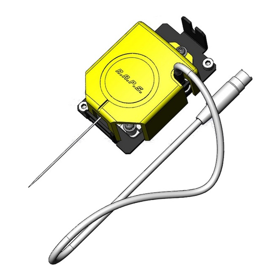
1-1 3D Scanning Sensor Unit Part Names and Functions Probe cover This cover protects the probe. When not using the sensor unit, be sure to attach the probe cover. Probe This touches the scan object and senses its shape. Connector This is the connector for con- nection to the modeling ma- chine. -
Page 12: Installing The Sensor Unit
1-2 Installing the Sensor Unit Installing the Sensor Unit Before you carry out this operation, switch off the power to the model- CAUTION ing machine. Failing to do so may result in sudden movement of the machine, causing the hands or fingers to become caught and resulting in injury. -
Page 13: To Reinstall The Spindle Unit
1-2 Installing the Sensor Unit Slightly loosen the cap screw shown in the figure. Turn the connector cover to open it. Retighten the cap screw. Hexagonal wrench (2.5 mm) Insert the cable for the sensor unit into the connector. Detach the probe cover. CAUTION Be sure to remove the probe cover when performing scanning. -
Page 14: Preparing The Programs
2 below. Log on to Windows as "Administrators." Roland Software Package Insert the Roland Software Package CD-ROM into the computer. (Windows Vista only: When the automatic play- back window appears, click [Run menu.exe].) - Page 15 1-3 Preparing the Programs Click the program you want to install and setup. Windows XP The setup program starts. Follow the messages to carry out setup and finish setting up the program. Windows Vista The [User Account Control] appears, click [Al- low].
-
Page 16: Step 2: Making The Settings For Dr. Picza3
Procedure Turn on the power to the modeling machine. From the [Start] menu, click [All Programs] - [Roland Dr. PICZA3] - [Dr. PICZA3]. Go to the [File] menu and click [Preferences]. For [Port], select the model name of the mod- eling machine you're using. -
Page 17: Chapter 2 Use And Operation As A 3D Scanner
Chapter 2 Use and Operation As a 3D Scanner... -
Page 18: Operation As A 3D Scanner
2-1 Operation As a 3D Scanner Operation As a 3D Scanner Startup Close the front cover. Switch on the main power switch. The POWER light comes on. Press the Sub power button. The machine starts up, and initialization is per- formed. -
Page 19: Objects That Can And Cannot Be Scanned
2-1 Operation As a 3D Scanner Objects That Can and Cannot Be Scanned Objects Unsuitable for Scanning Objects that change shape when touched by the probe cannot be scanned. For example, objects such as items made of soft rubber or fuzzy stuffed animals cannot be scanned. Depending on the configuration of the object, error equal to about the radius of the probe (0.5 mm) may occur. -
Page 20: Mounting The Object To Scan
2-1 Operation As a 3D Scanner Mounting the Object to Scan Mounting the Object to Scan Secure in place with the surface to scan facing up. Secure firmly to keep from moving during scanning. When loading an object to scan, make sure that all sides and the top of CAUTION the object are within the scannable area. -
Page 21: Using The Included Programs
2-2 Using the Included Programs User's Manuals for the Programs Description of Basic Operation See page 21, "Chapter 3 Basic Scanning Operation" Detailed Description You can find detailed explanations of the programs in the online help (electronic-format manuals). Dr.PICZA3 From the [Start] menu, click [All Programs] - [Ro- land Dr. -
Page 22: Amount Of Computer Memory Required
2-2 Using the Included Programs Amount of Computer Memory Required Important Note about Required Memory The amount of memory required increases proportionally as the dimensions of the scanning area grow larger or as the scanning pitch is made finer. Insufficient memory can slow down the operation of the computer, and even make it appear to freeze. -
Page 23: Chapter 3 Basic Scanning Operation
Chapter 3 Basic Scanning Opera- tion... -
Page 24: Learning The Basics Of Scanning
Procedure Start Dr. PICZA3 and display the [Settings for Scanning] dialog box. From the [Start] menu, click [All Pro- grams] - [Roland Dr. PICZA3] - [Dr. PICZA3]. Click [Scan]. Make the settings for the area to scan (width and depth). - Page 25 3-1 Learning the Basics of Scanning Make the settings for the area to scan (height direction). Enter the lower limit of the scanning area (the distance of the location from the table surface). Click this check box to select it. Find the highest location on the scan object.
-
Page 26: Step 2: Checking The Scanning Results
3-1 Learning the Basics of Scanning Step 2: Checking the Scanning Results You can preview the results while dragging the object to change its orientation and positioning. These change how the object moves when dragged (rotation, sliding, or zoom). These change the view. The three-dimensional item that has been scanned is called the "object."... -
Page 27: Chapter 4 Appendix
Chapter 4 Appendix... -
Page 28: What To Do If
If the same error display occurs, consult your authorized Roland dealer or service center. Other Symptoms Scanning ended, but the computer then Scanning is impossible stopped. -
Page 29: Specifications
4-2 Specifications Scanning-mode Specifications These are the main specifications of the MDX-40series or TS-30 when the ZSC-1 is installed. MDX-40series/TS-30 (ZSC-1 installed) Maximum scanning area 305 (X) x 305 (Y) x 60 (Z) mm (12 (X) x 12 (Y) x 2-5/16 (Z) in.) Distance from probe tip to table Maximum 92.4 mm (3-5/8 in)