Table of Contents
Advertisement
Advertisement
Table of Contents

Related Manuals for Asus PRIME TRX40-PRO


Summary of Contents for Asus PRIME TRX40-PRO
- Page 1 PRIME TRX40-...
- Page 2 Product warranty or service will not be extended if: (1) the product is repaired, modified or altered, unless such repair, modification of alteration is authorized in writing by ASUS; or (2) the serial number of the product is defaced or missing.
-
Page 3: Table Of Contents
Contents Safety information ...................... vi About this guide ......................vii PRIME TRX40-PRO specifications summary ............ix Package contents ..................... xiv Installation tools and components ................xv Chapter 1: Product Introduction Before you proceed ................... 1-1 Motherboard layout ..................1-2 Central Processing Unit (CPU) ..............1-4 System memory .................. - Page 4 3.6.13 AMD Overclocking ..............3-17 Monitor menu ................... 3-18 Boot menu ....................3-18 Tool menu ....................3-20 3.9.1 ASUS EZ Flash 3 Utility ............3-20 3.9.2 Secure Erase ................3-21 3.9.3 ASUS User Profile..............3-22 3.9.4 ASUS SPD Information ............. 3-22 3.9.5...
- Page 5 Chapter 4: RAID Support AMD RAID Array configurations ............... 4-1 4.1.1 RAID definitions ................4-1 Appendix Q-Code table ......................A-1 Notices ........................A-5 ASUS contact information ..................A-10...
-
Page 6: Safety Information
Safety information Electrical safety • To prevent electrical shock hazard, disconnect the power cable from the electrical outlet before relocating the system. • When adding or removing devices to or from the system, ensure that the power cables for the devices are unplugged before the signal cables are connected. If possible, disconnect all power cables from the existing system before you add a device. -
Page 7: About This Guide
Refer to the following sources for additional information and for product and software updates. ASUS website The ASUS website (www.asus.com) provides updated information on ASUS hardware and software products. Optional documentation Your product package may include optional documentation, such as warranty flyers, that may have been added by your dealer. -
Page 8: Conventions Used In This Guide
Conventions used in this guide To ensure that you perform certain tasks properly, take note of the following symbols used throughout this manual. DANGER/WARNING: Information to prevent injury to yourself when trying to complete a task. CAUTION: Information to prevent damage to the components when trying to complete a task. -
Page 9: Prime Trx40-Pro Specifications Summary
3466(O.C) / 3400(O.C) / 3200 / 3000 / 2933 / 2800 / 2666 / 2400 / 2133 MHz ECC and non-ECC, Unbuffered memory** Quad Channel Memory Architecture Please refer to Memory QVL (Qualified Vendors Lists) on www.asus.com for details. 3rd Gen AMD Ryzen™ Threadripper™ Desktop Processors - 3 x PCIe 4.0 x16 Safeslots (supports x16/x16/x16 mode) - Page 10 PRIME TRX40-PRO specifications summary Realtek S1220 8-channel high definition audio CODEC featuring Crystal Sound 3 - Power pre-regulator reduces power input noise to ensure consistent performance - Separate layer for left and right track, ensuring both sound deliver equal quality...
- Page 11 - ASUS NODE: hardware control interface - Turbo LAN <EZ DIY> Pre-mounted I/O Shield FlexKey Q-Design - ASUS Q-Code - ASUS Q-Connector - ASUS Q-DIMM - ASUS Q-LED (CPU, DRAM, VGA, Boot Device LED) - ASUS Q-Slot (continued on the next page)
- Page 12 Quiet Thermal Design: ASUS Quiet Thermal - ASUS Fan Xpert 4 Solution - ASUS Stylish MOS & M.2 heatsink, chipset fan with heatsink Design 1 x BIOS FlashBack™ button 1 x Optical S/PDIF out 1 x Intel LAN (RJ45) port ®...
- Page 13 EZ Update Anti-virus software (OEM version) Windows 10 64-bit Operating System ® 12” x 9.6” (30.5 cm x 24.4 cm) Form Factors • Specifications are subject to change without notice. • Visit the ASUS website for the software manual. xiii...
-
Page 14: Package Contents
Package contents Check your motherboard package for the following items. Motherboard 1 x PRIME TRX40-PRO motherboard 1 x Addressable LED extension cable Cables 1 x RGB LED extension cable 4 x SATA 6.0Gb/s cables 1 x M.2 Screw package 1 x M.2 E-key Screw package Accessories 1 x M.2 22110 vertical bracket... -
Page 15: Installation Tools And Components
Installation tools and components 1 Bag of screws Screwdriver PC chassis Power supply unit AMD Socket sTRX4 CPU AMD Socket sTRX4 compatible CPU Fan DDR4 DIMM SATA hard disk drive SATA optical disc drive (optional) Graphics card (optional) The tools and components in the table above are not included in the motherboard package. -
Page 17: Chapter 1: Product Introduction
• Unplug the power cord from the wall socket before touching any component. • Before handling components, use a grounded wrist strap or touch a safely grounded object or a metal object, such as the power supply case, to avoid damaging them due to static electricity. • Hold components by the edges to avoid touching the ICs on them. • Whenever you uninstall any component, place it on a grounded antistatic pad or in the bag that came with the component. • Before you install or remove any component, ensure that the ATX power supply is switched off or the power cord is detached from the power supply. Failure to do so may cause severe damage to the motherboard, peripherals, or components. PRIME TRX40-PRO... -
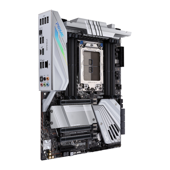
Page 18: Motherboard Layout
Motherboard layout Refer to Internal connectors and Rear I/O connection for more information about rear panel connectors and internal connectors. Chapter 1: Product Introduction... - Page 19 10. SATA 6Gb/s connector 1-13 11. Chipset Fan connector 1-16 12. Clear RTC RAM jumper 1-10 13. System Panel connector 1-22 14. USB 2.0 connector 1-16 15. Node connector 1-18 16. Thermal Sensor connector 1-18 17. Power button 18. Q-Code LED 1-11 19. Front Panel Audio connector 1-21 20. M.2 Wi-Fi slot 1-14 21. LED connector 1-21 PRIME TRX40-PRO...
-
Page 20: Central Processing Unit (Cpu)
Central Processing Unit (CPU) The motherboard comes with an AMD Socket sTRX4 for 3rd Gen AMD Ryzen™ Threadripper™ Series Desktop Processors. • The Socket sTRX4 has a different pinout design. Ensure that you use a CPU designed for the Socket sTRX4. • The CPU fits in only one correct orientation. DO NOT force the CPU into the socket to prevent bending the connectors on the CPU and damaging the CPU. • Ensure that all power cables are unplugged before installing the CPU. • Overclocking AMD processors, including without limitation, altering clock frequencies / multipliers or memory timing / voltage, to operate beyond their stock specifications will void any applicable AMD product warranty, even when such overclocking is enabled via AMD hardware and/or software. This may also void warranties offered by the system manufacturer or retailer. Users assume all risks and liabilities that may arise out of overclocking AMD processors, including, without limitation, failure of or damage to hardware, reduced system performance and/or data loss, corruption or vulnerability Chapter 1: Product Introduction... -
Page 21: System Memory
System memory The motherboard comes with Dual Inline Memory Modules (DIMM) slots designed for DDR4 (Double Data Rate 4) memory modules. A DDR4 memory module is notched differently from a DDR, DDR2, or DDR3 module. DO NOT install a DDR, DDR2, or DDR3 memory module to the DDR4 slot. Recommended memory configurations PRIME TRX40-PRO... -
Page 22: Memory Configurations
Memory configurations You may install 4 GB, 8 GB, 16 GB, and 32 GB unbuffered ECC and non-ECC DDR4 DIMMs into the DIMM sockets. You may install varying memory sizes in Channel A, Channel B, Channel C, and Channel D. The system maps the total size of the lower-sized channel for the quad-channel configuration. Any excess memory from the higher-sized channel is then mapped for single-channel operation. • The default memory operation frequency is dependent on its Serial Presence Detect (SPD), which is the standard way of accessing information from a memory module. Under the default state, some memory modules for overclocking may operate at a lower frequency than the vendor-marked value. • For system stability, use a more efficient memory cooling system to support a full memory load or overclocking condition. • Always install the DIMMS with the same CAS Latency. For an optimum compatibility, we recommend that you install memory modules of the same version or data code (D/C) from the same vendor. Check with the vendor to get the correct memory modules. • Visit the ASUS website for the latest QVL. Chapter 1: Product Introduction... -
Page 23: Expansion Slots
Expansion slots Unplug the power cord before adding or removing expansion cards. Failure to do so may cause you physical injury and damage motherboard components. PRIME TRX40-PRO... - Page 24 Recommended VGA configuration 3rd Gen AMD Ryzen™ Threadripper™ Desktop Processors Slot Description Single VGA ® /CFX PCIe 4.0 x16_1 x16 PCIe 4.0 x16_2 PCIe 4.0 x16_3 • We recommend that you provide sufficient power when running CrossFireX™ or SLI ® mode. • Ensure to connect both 8-pin power plugs when running CrossFireX™ or SLI mode. ® • Connect a chassis fan to the chassis fan connectors when using multiple graphics cards for better thermal environment. Chapter 1: Product Introduction...
-
Page 25: Onboard Buttons
Onboard buttons Power button Press the Power button to power up the system, or put the system into sleep or soft- off mode (depending on the operating system settings). The button also lights up when the system is plugged to a power source, indicating that you should shut down the system and unplug the power cable before removing or installing any motherboard component. PRIME TRX40-PRO... -
Page 26: Onboard Jumpers
Onboard jumpers Clear RTC RAM jumper The Clear RTC RAM jumper allows you to clear the Real Time Clock (RTC) RAM in the CMOS, which contains the date, time, system passwords, and system setup parameters. To erase the RTC RAM: Turn OFF the computer and unplug the power cord. Short-circuit pin 1-2 with a metal object or jumper cap for about 5-10 seconds. Plug the power cord and turn ON the computer. Hold down the <Del> key during the boot process and enter BIOS setup to re-enter data. DO NOT short-circuit the pins except when clearing the RTC RAM. Short-circuiting or placing a jumper cap will cause system boot failure! If the steps above do not help, remove the onboard button cell battery and move the jumper again to clear the CMOS RTC RAM data. After clearing the CMOS, reinstall the button cell battery. Chapter 1: Product Introduction 1-10... -
Page 27: Onboard Leds
Onboard LEDs Q LEDs The Q LEDs check key components (CPU, DRAM, VGA, and booting devices) during the motherboard booting process. If an error is found, the critical component’s LED stays lit up until the problem is solved. The Q LEDs provide the most probable cause of an error code as a starting point for troubleshooting. The actual cause may vary from case to case. Q-Code LED The Q-Code LED design provides you with a 2-digit error code that displays the system status. • The Q-Code LEDs provide the most probable cause of an error code as a starting point for troubleshooting. The actual cause may vary from case to case. • Please refer to the Q-Code table in the Appendix section for more details. PRIME TRX40-PRO 1-11... - Page 28 8-pin Power Plug LED The 8-pin Power Plug LED lights up to indicate that the 8-pin power plug is not connected. • Ensure to connect both 8-pin power plugs. • Due to the CPU minimum power consumption requirement, we recommend using a PSU with 850W or above. Chapter 1: Product Introduction 1-12...
-
Page 29: Internal Connectors
Internal connectors SATA 6Gb/s connector The SATA 6Gb/s connector allows you to connect SATA devices such as optical disc drives and hard disk drives via a SATA cable. If you installed SATA storage devices, you can create a RAID 0, 1, and 10 configuration through the onboard AMD TRX40 chipset. • These connectors are set to [AHCI] by default. If you intend to create a SATA RAID set using these connectors, set the SATA Mode Selection item in the BIOS to [RAID]. • Before creating a RAID set, refer to the RAID Configuration Guide. You can download the RAID Configuration Guide from the ASUS website. PRIME TRX40-PRO 1-13... - Page 30 M.2 slot The M.2 slot allows you to install M.2 devices such as M.2 SSD modules. • M.2_1 and M.2_2 sockets support PCIe 4.0 x4 M Key design and type 2242 / 2260 / 2280 / 22110 storage devices. • M.2_3 socket supports PCIe 4.0 x4 and SATA modes vertical M Key design and type 2242 / 2260 / 2280 / 22110 storage devices. • The M.2 SSD module is purchased separately. • Use the bundled bracket to install a vertical M.2 SSD module to the M.2_3 socket, refer to the M.2 Installation section for more details. M.2 Wi-Fi slot The M.2 Wi-Fi slot allows you to install an M.2 Wi-Fi module (E-key, type 2230). The M.2 Wi-Fi module is purchased separately. Chapter 1: Product Introduction 1-14...
- Page 31 USB 3.2 Gen 2 connector The USB 3.2 Gen 2 connector allows you to connect a USB 3.2 Gen 2 module for additional USB 3.2 Gen 2 ports. The USB 3.2 Gen 2 connector provides data transfer speeds of up to 10 Gb/s. The USB 3.2 Gen 2 module is purchased separately. USB 3.2 Gen 1 connector The USB 3.2 Gen 1 connector allows you to connect a USB 3.2 Gen 1 module for additional USB 3.2 Gen 1 ports. The USB 3.2 Gen 1 connector provides data transfer speeds of up to 5 Gb/s. The USB 3.2 Gen 1 module is purchased separately. The plugged USB 3.2 Gen 1 device may run on xHCI or EHCI mode depending on the operating system’s setting. PRIME TRX40-PRO 1-15...
- Page 32 USB 2.0 connector The USB 2.0 connector allows you to connect a USB module for additional USB 2.0 ports. The USB 2.0 connector provides data transfer speeds of up to 480 MB/s connection speed. DO NOT connect a 1394 cable to the USB connectors. Doing so will damage the motherboard! The USB 2.0 module is purchased separately. Chipset Fan connector The Chipset Fan connector is for connecting the chipset fan on the integrated heatsink. Chapter 1: Product Introduction 1-16...
- Page 33 CPU_FAN and CPU_OPT connectors. Header Max. Current Max. Power Default Speed Shared Control CPU_FAN Q-Fan Controlled CPU_OPT Q-Fan Controlled CHA_FAN1 Q-Fan Controlled CHA_FAN2 Q-Fan Controlled CHA_FAN3 Q-Fan Controlled CHIPSET_FAN Q-Fan Controlled AIO_PUMP Full-Speed W_PUMP+ Full-Speed PRIME TRX40-PRO 1-17...
- Page 34 Node connector The Node connector allows you to connect a compatible PSU or control a compatible fan extension card. Visit www.asus.com for more information about the devices and the latest compatibility list. Thermal Sensor connector The Thermal Sensor connector allows you to connect a sensor to monitor the temperature of the devices and the critical components inside the motherboard. Connect the thermal sensor and place it on the device or the motherboard’s component to detect its temperature. The thermal sensor is purchased separately. Chapter 1: Product Introduction 1-18...
- Page 35 Addressable Gen2 LED connector The Addressable Gen2 LED connector allows you to connect individually addressable RGB WS2812B LED strips or WS2812B based LED strips. The Addressable Gen2 LED connector supports WS2812B addressable RGB LED strips (5V/Data/Ground), with a maximum power rating of 3A (5V) and a maximum of 120 LEDs. Before you install or remove any component, ensure that the power supply is switched off or the power cord is detached from the power supply. Failure to do so may cause severe damage to the motherboard, peripherals, or components. • Actual lighting and color will vary with LED strip. • If your LED strip does not light up, check if the addressable RGB LED strip is connected in the correct orientation, and the 5V connector is aligned with the 5V header on the motherboard. • The addressable RGB LED strip will only light up when the system is powered on. • The addressable RGB LED strip is purchased separately. PRIME TRX40-PRO 1-19...
- Page 36 AURA RGB LED connector The AURA RGB LED connector allows you to connect RGB LED strips. The AURA RGB LED connector supports 5050 RGB multi-color LED strips (12V/G/R/B), with a maximum power rating of 3A (12V). Before you install or remove any component, ensure that the power supply is switched off or the power cord is detached from the power supply. Failure to do so may cause severe damage to the motherboard, peripherals, or components. • Actual lighting and color will vary with LED strip. • If your LED strip does not light up, check if the RGB LED extension cable and the RGB LED strip is connected in the correct orientation, and the 12V connector is aligned with the 12V header on the motherboard. • The LED strip will only light up when the system is powered on. • The LED strip is purchased separately. Chapter 1: Product Introduction 1-20...
- Page 37 LED connector The LED connector is for connecting the LED PCB on your I/O cover. Front Panel Audio connector The front panel audio connector is for a chassis-mounted front panel audio I/O module that supports HD Audio. Connect one end of the front panel audio I/O module cable to this connector. We recommend that you connect a high-definition front panel audio module to this connector to avail of the motherboard’s high-definition audio capability. PRIME TRX40-PRO 1-21...
- Page 38 System Panel connector The System Panel connector supports several chassis-mounted functions. • System Power LED connector (PLED) The 2-pin connector allows you to connect the System Power LED. The System Power LED lights up when the system is connected to a power source, or when you turn on the system power, and blinks when the system is in sleep mode. • Storage Device Activity LED connector (HDLED) The 2-pin connector allows you to connect the Storage Device Activity LED. The Storage Device Activity LED lights up or blinks when data is read from or written to the storage device or storage device add-on card. • System Warning Speaker connector (SPEAKER) The 4-pin connector allows you to connect the chassis-mounted system warning speaker. The speaker allows you to hear system beeps and warnings. • Power Button/Soft-off Button connector (PWRBTN) The 3-1 pin connector allows you to connect the system power button.
-
Page 39: Power Connectors
Power connectors These Power connectors allow you to connect your motherboard to a power supply. The power supply plugs are designed to fit in only one orientation, find the proper orientation and push down firmly until the power supply plugs are fully inserted. • Ensure to connect both 8-pin power plugs. • Due to the CPU minimum power consumption requirement, we recommend using a PSU with 850W or above. PRIME TRX40-PRO 1-23... - Page 40 Chapter 1: Product Introduction 1-24...
-
Page 41: Building Your Pc System
Load plate Use your fingers to pull up the tabs on Load plate both sides of the rail frame to release the rail frame, then lift the rail frame to its fully open position. Rail frame External cap PRIME TRX40-PRO... - Page 42 Remove the external cap. External cap Rail frame PnP cap Slide the carrier frame with CPU into Carrier frame the rail frame until you hear a click with CPU sound, then remove the PnP cap. PnP cap Gently press down the rail frame until it latches to the socket housing, then press down the load plate.
- Page 43 Material to the CPU. The load plate screws are Torx T20 models. A torque value of 12 inch-lbf is recommended. Apply the Thermal Interface Material to the CPU heatsink and CPU before you install the heatsink and fan if necessary. PRIME TRX40-PRO...
-
Page 44: Cooling System Installation
2.1.2 Cooling system installation To install the CPU heatsink and fan assembly: Chapter 2: Basic Installation... -
Page 45: Motherboard Installation
DO NOT over tighten the screws! Doing so can damage the motherboard. • Ensure that the space above the installed motherboard at least 8cm to prevent the MOS heatsink from interfering with the radiator or chassis fans. • We recommend using an E-ATX chassis when installing this motherboard. PRIME TRX40-PRO... -
Page 46: Dimm Installation
2.1.4 DIMM installation To remove a DIMM Chapter 2: Basic Installation... -
Page 47: Atx Power Connection
2.1.5 ATX power connection Ensure to connect the two 8-pin power plugs. PRIME TRX40-PRO... -
Page 48: Sata Device Connection
2.1.6 SATA device connection Chapter 2: Basic Installation... -
Page 49: Front I/O Connector
2.1.7 Front I/O connector To install ASUS Q-Connector To install USB 3.2 Gen 2 connector USB 3.2 Gen 2 This connector will only fit in one orientation. Push the connector until it clicks into place. To install USB 3.2 Gen 1 connector To install USB 2.0 connector... -
Page 50: Expansion Card Installation
2.1.8 Expansion card installation To install PCIe x16 cards To install PCIe x4 cards 2-10 Chapter 2: Basic Installation... -
Page 51: M.2 Installation
2.1.9 M.2 installation Supported M.2 type varies per motherboard. For M.2_1 and M.2_2 (Type 2242 / 2260 / 2280 M.2) PRIME TRX40-PRO 2-11... - Page 52 For M.2_1 and M.2_2 (Type 22110 M.2) 2-12 Chapter 2: Basic Installation...
- Page 53 For M.2_3 (Type 2242 / 2260 / 2280 / 22110 M.2) PRIME TRX40-PRO 2-13...
-
Page 54: Fan Bracket Installation
2.1.10 Fan bracket installation To install the MOS FAN bracket and fan When using high performance settings whilst overclocking, ensure to install the MOS FAN bracket for additional fan(s). • You may install 12V (1A, 12W), 40mm x 40mm fans. •... -
Page 55: M.2 Wi-Fi Module And Antenna Installation
2.1.11 M.2 Wi-Fi module and antenna installation Installing the M.2 W-Fi Module • Ensure that the ASUS 2x2 dual band Wi-Fi antenna is securely installed to the Wi-Fi ports. • Ensure that the antenna is at least 20 cm away from all persons. -
Page 56: Bios Update Utility
• Updating BIOS may have risks. If the BIOS program is damaged during the process and results to the system’s failure to boot up, please contact your local ASUS Service Center. 2-16... -
Page 57: Motherboard Rear And Audio Connections
USB 3.2 Gen 2 ports 34. Lower port supports BIOS FlashBack™ function. Optical S/PDIF OUT port Audio I/O ports** * and ** : Refer to the tables on the next page for LAN port LEDs, and audio port definitions. PRIME TRX40-PRO 2-17... - Page 58 * LAN ports LED indications Activity Link LED Speed LED Status Description Status Description ACT/LINK SPEED No link 10 Mbps connection ORANGE Linked ORANGE 100 Mbps connection ORANGE Data activity GREEN 1 Gbps connection (Blinking) LAN port ORANGE Ready to (Blinking then wake up from Steady)
-
Page 59: Audio I/O Connections
2.3.2 Audio I/O connections Audio I/O ports Connect to Headphone and Mic Connect to Stereo Speakers Connect to 2-channel Speakers PRIME TRX40-PRO 2-19... - Page 60 Connect to 4 channel Speakers Connect to 6 channel Speakers Connect to 8 Speakers 2-20 Chapter 2: Basic Installation...
-
Page 61: Starting Up For The First Time
While the system is ON, press the power button for less than four seconds to put the system on sleep mode or soft-off mode, depending on the BIOS setting. Press the power button for more than four seconds to let the system enter the soft-off mode regardless of the BIOS setting. PRIME TRX40-PRO 2-21... - Page 62 2-22 Chapter 2: Basic Installation...
-
Page 63: Chapter 3: Bios Setup
BIOS Setup Knowing BIOS The new ASUS UEFI BIOS is a Unified Extensible Interface that complies with UEFI architecture, offering a user-friendly interface that goes beyond the traditional keyboard- only BIOS controls to enable a more flexible and convenient mouse input. You can easily navigate the new UEFI BIOS with the same smoothness as your operating system. -
Page 64: Bios Setup Program
Clear CMOS jumper to clear RTC RAM. • The BIOS setup program does not support the Bluetooth devices. Please visit ASUS website for the detailed BIOS content manual. BIOS menu screen The BIOS Setup program can be used under two modes: EZ Mode and Advanced Mode. -
Page 65: Advanced Mode
Pop-up Menu Menu bar Language MyFavorite(F3) Qfan Control(F6) AURA ON/OFF(F4) Menu items General help Last modified settings Hot Keys Go back to EZ Mode Search on the FAQ Displays a quick overview of the system status and prediction PRIME TRX40-PRO... -
Page 66: Menu Bar
Menu bar The menu bar on top of the screen has the following main items: For saving the frequently-used system settings and configuration. My Favorites For changing the basic system configuration Main For changing the overclocking settings Ai Tweaker For changing the advanced system settings Advanced For displaying the system temperature, power status, and changing Monitor... -
Page 67: Hot Keys
Move your mouse over this button to show a QR code, scan this QR code on your mobile device to connect to the BIOS FAQ web page of the ASUS support website. You can also scan the following QR code: Hot keys This button above the menu bar contains the navigation keys for the BIOS setup program. -
Page 68: Ez Mode
3.2.2 EZ Mode The EZ Mode provides you an overview of the basic system information, and allows you to select the display language, system performance, mode and boot device priority. To access the Advanced Mode, select Advanced Mode or press the <F7> hotkey for the advanced BIOS settings. -
Page 69: Q-Fan Control
Click to activate DC Mode configured PWM Mode Select a profile to Click to apply the fan setting apply to your fans Click to undo the Click to go back to main menu changes Select to manually configure your fans PRIME TRX40-PRO... - Page 70 Configuring fans manually Select Manual from the list of profiles to manually configure your fans’ operating speed. Speed points Select to manually configure your fans To configure your fans: Select the fan that you want to configure and to view its current status. Click and drag the speed points to adjust the fans’...
-
Page 71: My Favorites
My Favorites is your personal space where you can easily save and access your favorite BIOS items. My Favorites comes with several performance, power saving, and fast boot related items by default. You can personalize this screen by adding or removing items. PRIME TRX40-PRO... - Page 72 Adding items to My Favorites To add BIOS items: Press <F3> on your keyboard or click MyFavorite(F3) from the BIOS screen to open Setup Tree Map screen. On the Setup Tree Map screen, select the BIOS items that you want to save in My Favorites screen.
-
Page 73: Main Menu
This item allows you to set the BCLK frequency to enhance the system performance. Use the <+> or <-> to adjust the value. We recommend you to set the value based on the CPU specification, as high BCLK frequencies may damage the CPU permanently. PRIME TRX40-PRO 3-11... -
Page 74: Advanced Menu
CPU Core Ratio This item allows you to set the CPU core ratios. Configuration options: [Auto] [Sync All Cores] [Per Core] [By Specific Core] This item allows you to automatically overclock the CPU and DRAM frequencies and voltage for an enhanced system performance. [Keep Current Settings] Keep the current settings without changing anything. -
Page 75: Pci Subsystem Settings
BME DMA Mitigation Allows you to re-enable Bus Master Attribute disabled during Pci enumeration for PCI Bridges after SMM Locked. Configuration options: [On] [Off] Changing PCI Device(s) settings may have unwanted side effects! System may HANG! Proceed with caution. PRIME TRX40-PRO 3-13... -
Page 76: Usb Configuration
3.6.4 USB Configuration The items in this menu allow you to change the USB-related features. The Mass Storage Devices item shows the auto-detected values. If no USB device is detected, the item shows None. Legacy USB Support [Enabled] Your system supports the USB devices in legacy operating systems. [Disabled] Your USB devices can be used for BIOS setup only and cannot be recognized in the boot devices list. -
Page 77: Onboard Devices Configuration
Configuration options: [Disabled] [Enabled] M.2_3(Gray) M.2_3(Gray) This item allows you to rename the AMD APU M.2 ports. 3.6.8 Onboard Devices Configuration The items in this menu allow you to switch between PCIe Lanes and configure onboard devices. PRIME TRX40-PRO 3-15... - Page 78 PCIEX16_1 Bandwidth [X16 Mode] The PCIe x16_1 slot runs at x16 mode. [PCIe RAID Mode] The four PCIe x16 slots run at x4+x4+x4+x4 mode, which allows you to create a RAID array for up to 4 PCIe devices. Use PCIe RAID Mode when installing the Hyper M.2 x16 card or other M.2 adapter cards. Installing other devices when using PCIe RAID Mode may cause your PC to fail to boot PCIEX16_2 Bandwidth [X8 Mode]...
-
Page 79: Apm Configuration
The items in this menu shows the AMD Common BIOS Specifications. 3.6.12 AMD PBS The items in this menu shows the AMD PBS Setup Page. 3.6.13 AMD Overclocking The items in this menu shows the AMD Overclocking Setup Page. PRIME TRX40-PRO 3-17... -
Page 80: Monitor Menu
Monitor menu The Monitor menu displays the system temperature/power status, and allows you to change the fan settings. Scroll down to display the other BIOS items. Q-fan Configuration Qfan Tuning Click this item to automatically detect the lowest speed and configure the minimum duty cycle for each fan. -
Page 81: Secure Boot
Configuration options: [Legacy only] [UEFI driver first] Secure Boot This item allows you to configure the Windows Secure Boot settings and manage its keys to ® protect the system from unauthorized access and malwares during POST. PRIME TRX40-PRO 3-19... -
Page 82: Tool Menu
3.9.1 ASUS EZ Flash 3 Utility This item allows you to run ASUS EZ Flash 3. When you press <Enter>, a confirmation message appears. Use the left/right arrow key to select between [Yes] or [No], then press <Enter> to confirm your choice. -
Page 83: Secure Erase
Locked. SSDs might be locked if the Secure Erase process is either incomplete or was stopped. This may be due to a third party software that uses a different password defined by ASUS. You have to unlock the SSD in the software before proceeding with Secure Erase. -
Page 84: Asus User Profile
3.9.5 ASUS Armoury Crate This item allows you to enable or disable the ASUS Armoury Crate. The ASUS Armoury Crate is a fixed Advanced Configuration and Power Interface (ACPI) table that provides Windows with a platform binary that the operating system can execute. -
Page 85: Exit Menu
<Esc>, a confirmation window appears. Select Yes to discard changes and exit. Launch EFI Shell from USB drives This item allows you to attempt to launch the EFI Shell application (shellx64.efi) from one of the available filesystem devices. PRIME TRX40-PRO 3-23... -
Page 86: Updating Bios
3.11 Updating BIOS The ASUS website publishes the latest BIOS versions to provide enhancements on system stability, compatibility,and performance. However, BIOS updating is potentially risky. If there is no problem using the current version of BIOS, DO NOT manually update the BIOS. -
Page 87: Asus Ez Flash 3
3.11.2 ASUS EZ Flash 3 ASUS EZ Flash 3 allows you to download and update to the latest BIOS without having to use a bootable floppy disk or an OS-based utility. To update the BIOS by USB: Insert the USB flash disk that contains the latest BIOS file to the USB port. -
Page 88: Asus Crashfree Bios 3
3.11.3 ASUS CrashFree BIOS 3 The ASUS CrashFree BIOS 3 utility is an auto recovery tool that allows you to restore the BIOS file when it fails or gets corrupted during the updating process. You can restore a corrupted BIOS file using the motherboard support USB drive that contains the BIOS file. -
Page 89: Chapter 4: Raid Support
The motherboard comes with the RaidXpert2 Configuration Utility that supports Volume, RAIDABLE, RAID 0, RAID 1, and RAID 10 (depends on system licensing) configurations. For more information on configuring your RAID sets, please refer to the RAID Configuration Guide which you can find at https://www.asus.com/support. 4.1.1 RAID definitions Volume provides the ability to link-together storage from one or several disks, regardless of the size of the space on those disks. - Page 90 Chapter 4: RAID Support...
-
Page 91: Appendix
CPU self test failed or possible CPU cache error CPU micro-code is not found or micro-code update is failed Internal CPU error Reset PPI is not available Reserved for future AMI error codes 5C – 5F (continued on the next page) PRIME TRX40-PRO... - Page 92 Q-Code table Code Description S3 Resume is stared (S3 Resume PPI is called by the DXE IPL) S3 Boot Script execution Video repost OS S3 wake vector call Reserved for future AMI progress codes E4 – E7 S3 Resume Failed S3 Resume PPI not Found S3 Resume Boot Script Error S3 OS Wake Error...
- Page 93 Reserved for ASL (see ASL Status Codes section below) Ready To Boot event Legacy Boot event Exit Boot Services event Runtime Set Virtual Address MAP Begin Runtime Set Virtual Address MAP End Legacy Option ROM Initialization System Reset (continued on the next page) PRIME TRX40-PRO...
- Page 94 Q-Code table Code Description USB hot plug PCI bus hot plug Clean-up of NVRAM Configuration Reset (reset of NVRAM settings) B8– BF Reserved for future AMI codes CPU initialization error System Agent initialization error PCH initialization error Some of the Architectural Protocols are not available PCI resource allocation error.
-
Page 95: Notices
Notices FCC Compliance Information Responsible Party: Asus Computer International Address: 48720 Kato Rd., Fremont, CA 94538, USA Phone / Fax No: (510)739-3777 / (510)608-4555 This device complies with part 15 of the FCC Rules. Operation is subject to the following two conditions: (1) This device may not cause harmful interference, and (2) this device must accept any interference received, including interference that may cause undesired operation. - Page 96 Compliance Statement of Innovation, Science and Economic Development Canada (ISED) This device complies with Innovation, Science and Economic Development Canada licence exempt RSS standard(s). Operation is subject to the following two conditions: (1) this device may not cause interference, and (2) this device must accept any interference, including interference that may cause undesired operation of the device.
- Page 97 ASUS products sold in Vietnam, on or after September 23, 2011,meet the requirements of the Vietnam Circular 30/2011/TT-BCT. Các sản phẩm ASUS bán tại Việt Nam, vào ngày 23 tháng 9 năm2011 trở về sau, đều phải đáp ứng các yêu cầu của Thông tư 30/2011/TT-BCT của Việt Nam.
- Page 98 ASUS Recycling/Takeback Services ASUS recycling and takeback programs come from our commitment to the highest standards for protecting our environment. We believe in providing solutions for you to be able to responsibly recycle our products, batteries, other components as well as the packaging materials.
- Page 99 доступний на: www.asus.com/support Cijeli tekst EU izjave o sukladnosti dostupan je na: www.asus.com/support Türkçe AsusTek Computer Inc., bu aygıtın temel gereksinimlerle ve ilişkili Čeština Společnost ASUSTeK Computer Inc. tímto prohlašuje, že Yönergelerin diğer ilgili koşullarıyla uyumlu olduğunu beyan eder.
-
Page 100: Asus Contact Information
+1-510-608-4555 Web site http://www.asus.com/us/ Technical Support Support fax +1-812-284-0883 Telephone +1-812-282-2787 Online support https://www.asus.com/support/Product/ContactUs/ Services/questionform/?lang=en-us ASUS COMPUTER GmbH (Germany and Austria) Address Harkort Str. 21-23, 40880 Ratingen, Germany +49-2102-959931 Web site http://www.asus.com/de Online contact http://eu-rma.asus.com/sales Technical Support Telephone +49-2102-5789555 Support Fax...