Chapters
Table of Contents

Related Manuals for Asus Trooper B85


Summary of Contents for Asus Trooper B85
- Page 1 TROOPER B85...
- Page 2 Product warranty or service will not be extended if: (1) the product is repaired, modified or altered, unless such repair, modification of alteration is authorized in writing by ASUS; or (2) the serial number of the product is defaced or missing.
-
Page 3: Table Of Contents
Contents Safety information ...................... iv About this guide ......................iv Package contents ....................... vi TROOPER B85 specifications summary ..............vi Product introduction Before you proceed ..................1-1 Motherboard overview ................. 1-1 Central Processing Unit (CPU) ..............1-3 System memory .................... 1-6 Expansion slots .................... -
Page 4: Safety Information
Safety information Electrical safety • To prevent electrical shock hazard, disconnect the power cable from the electrical outlet before relocating the system. • When adding or removing devices to or from the system, ensure that the power cables for the devices are unplugged before the signal cables are connected. If possible, disconnect all power cables from the existing system before you add a device. -
Page 5: Conventions Used In This Guide
Refer to the following sources for additional information and for product and software updates. ASUS websites The ASUS website provides updated information on ASUS hardware and software products. Refer to the ASUS contact information. Optional documentation Your product package may include optional documentation, such as warranty flyers, that may have been added by your dealer. -
Page 6: Package Contents
® * Due to chipset limitations, memory modules higher than 1600 MHz will run at 1600MHz frequency for better stability. ** Refer to www.asus.com for the latest Memory QVL (Qualified Vendors List). Integrated Graphics Processor - Intel HD Graphics support ®... - Page 7 - USB 3.0 Boost featuring speedy USB 3.0 transmission features - Ai Charger - ASUS UEFI BIOS EZ Mode featuring friendly graphics user interface - AI Suite 3 - ASUS Q-LED (CPU, DRAM, VGA, Boot Device LED) - ASUS Q-Slot - ASUS Q-DIMM - ASUS O.C.
- Page 8 BIOS features 64 Mb Flash ROM, UEFI AMI BIOS, PnP, DMI2.7, WfM2.0, SM BIOS 2.7, ACPI 5.0, Multi-language BIOS, ASUS EZ Flash 2, ASUS CrashFree BIOS 3, My Favorites, Quick Note, Last Modified log, F12 PrintScreen, F3 Shortcut functions and ASUS DRAM SPD (Serial Presence Detect) memory...
-
Page 9: Product Introduction
The edge with external ports goes to the rear part of the chassis as indicated in the image below. 1.2.2 Screw holes Place six screws into the holes indicated by circles to secure the motherboard to the chassis. Do not overtighten the screws! Doing so can damage the motherboard. ASUS TROOPER B85... -
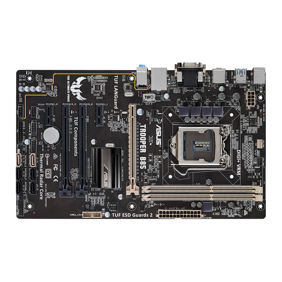
Page 10: Motherboard Layout
Place this side towards the rear of the chassis 1.2.3 Motherboard layout Chapter 1: Product introduction... -
Page 11: Central Processing Unit (Cpu)
1-18 13. Digital audio connector (4-1 pin SPDIF_OUT) 1-13 14. Front panel audio connector (10-1 pin AAFP) 1-13 15. Serial port connectors (10-1 pin COM) 1-18 Central Processing Unit (CPU) This motherboard comes with a surface mount LGA1150 socket designed for New 4th Generation Intel Core™ i7 / i5 / i3, Pentium and Celeron processors. ® ® ® Unplug all power cables before installing the CPU. • Upon purchase of the motherboard, ensure that the PnP cap is on the socket and the socket contacts are not bent. Contact your retailer immediately if the PnP cap is missing, or if you see any damage to the PnP cap/socket contacts/motherboard components. ASUS will shoulder the cost of repair only if the damage is shipment/ transit-related. • Keep the cap after installing the motherboard. ASUS will process Return Merchandise Authorization (RMA) requests only if the motherboard comes with the cap on the LGA1150 socket. • The product warranty does not cover damage to the socket contacts resulting from incorrect CPU installation/removal, or misplacement/loss/incorrect removal of the PnP cap. ASUS TROOPER B85... -
Page 12: Installing The Cpu
1.3.1 Installing the CPU Chapter 1: Product introduction... -
Page 13: Cpu Heatsink And Fan Assembly Installation
1.3.2 CPU heatsink and fan assembly installation Apply the Thermal Interface Material to the CPU heatsink and CPU before you install the heatsink and fan if necessary. To install the CPU heatsink and fan assembly ASUS TROOPER B85... -
Page 14: System Memory
To uninstall the CPU heatsink and fan assembly System memory 1.4.1 Overview This motherboard comes with two Double Data Rate 3 (DDR3) Dual Inline Memory Module (DIMM) sockets. A DDR3 module is notched differently from a DDR or DDR2 module. DO NOT install a DDR or DDR2 memory module to the DDR3 slot. According to Intel CPU spec, DIMM voltage below 1.65V is recommended to protect the ® CPU. Channel Sockets Channel A DIMM_A1 Channel B DIMM_B1 1.4.2 Memory configurations You may install 1GB, 2GB, 4GB, and 8GB unbuffered non-ECC DDR3 DIMMs into the DIMM sockets. Chapter 1: Product introduction... -
Page 15: Installing A Dimm
® or more memory on the motherboard, the actual usable memory for the OS can be about 3GB or less. For effective use of memory, we recommend that you do any of the following: Use a maximum of 3GB system memory if you are using a 32-bit Windows OS. ® I nstall a 64-bit Windows OS if you want to install 4GB or more on the ® motherboard. • This motherboard does not support DIMMs made up of 512 megabits (Mb) chips or less. • Memory modules with memory frequency higher than 2133 MHz and its corresponding timing or the loaded X.M.P. Profile is not the JEDEC memory standard. The stability and compatibility of these memory modules depend on the CPU’s capabilities and other installed devices. • The maximum 16GB memory capacity can be supported with 8GB or above DIMMs. ASUS will update the memory QVL once the DIMMs are available in the market. • The default memory operation frequency is dependent on its Serial Presence Detect (SPD), which is the standard way of accessing information from a memory module. Under the default state, some memory modules for overclocking may operate at a lower frequency than the vendor-marked value. • For system stability, use a more efficient memory cooling system to support a full memory load (2 DIMMs) or overclocking condition. • Refer to www.asus.com for the latest Memory QVL (Qualified Vendors List) 1.4.3 Installing a DIMM ASUS TROOPER B85... -
Page 16: Expansion Slots
To remove a DIMM Expansion slots In the future, you may need to install expansion cards. The following sub-sections describe the slots and the expansion cards that they support. Unplug the power cord before adding or removing expansion cards. Failure to do so may cause you physical injury and damage motherboard components. Chapter 1: Product introduction... -
Page 17: Installing An Expansion Card
PCI Express x1 slots This motherboard supports two PCI Express x1 network cards, SCSI cards, and other cards that comply with the PCI Express specifications. 1.5.4 PCI Express x16 slot This motherboard supports one PCI Express x16 graphics card that complies with the PCI Express specifications. IRQ assignments for this motherboard shared PCIE x16_1 shared PCIE x16_2 shared PCIE x16_3 shared PCIE x1_1 shared PCIE x1_2 shared Intel PCH SATA Controller shared HD Audio shared USB2.0_1 shared USB2.0_2 shared USB3.0 shared ASUS TROOPER B85... -
Page 18: Headers
Headers Clear RTC RAM (2-pin CLRTC) This header allows you to clear the Real Time Clock (RTC) RAM in CMOS. You can clear the CMOS memory of date, and system setup parameters by erasing the CMOS RTC RAM data. The onboard button cell battery powers the RAM data in CMOS, which include system setup information such as system passwords. To erase the RTC RAM: Turn OFF the computer and unplug the power cord. Use a metal object such as a screwdriver to short the two pins. Plug the power cord and turn ON the computer. Hold down the <Del> key during the boot process and enter BIOS setup to re- enter data. • If the steps above do not help, remove the onboard battery and short the two pins again to clear the CMOS RTC RAM data. After clearing the CMOS, reinstall the battery. • You do not need to clear the RTC when the system hangs due to overclocking. For system failure due to overclocking, use the CPU Parameter Recall (C.P.R.) feature. Shut down and reboot the system, then the BIOS automatically resets parameter settings to default values. 1-10 Chapter 1: Product introduction... -
Page 19: Connectors
ORANGE 100Mbps connection Orange (Blinking) Data activity GREEN 1Gbps connection LAN port Orange (Blinking Ready to wake then steady) up from S5 mode Line In port (light blue). This port connects the tape, CD, DVD player, or other audio sources. Line Out port (lime). This port connects a headphone or a speaker. In 4-channel, 6-channel, and 8-channel configurations, the function of this port becomes Front Speaker Out. Microphone port (pink). This port connects a microphone. To configure an 8-channel audio output: Use a chassis with HD audio module in the front panel to support an 8-channel audio output. ASUS TROOPER B85 1-11... - Page 20 Audio 2.1, 4.1, 5.1 or 7.1-channel configuration Headset Port 4.1-channel 5.1-channel 7.1-channel 2.1-channel Light Blue Line In Rear Speaker Out Rear Speaker Out Rear Speaker Out (Rear panel) Lime (Rear panel) Line Out Front Speaker Out Front Speaker Out Front Speaker Out Pink (Rear panel) Mic In Mic In Bass/Center Bass/Center Lime (Front panel) — — — Side Speaker Out For an 8-channel speaker setup, refer to the 7.1-channel configuration in the table. USB 2.0 ports 5 and 6. These two 4-pin Universal Serial Bus (USB) ports are for USB 2.0/1.1 devices. DVI-D port. This port is for any DVI-D compatible device. DVI-D can’t be converted to output RGB Signal to CRT and isn’t compatible with DVI-I. USB 2.0 ports 3 and 4. These two 4-pin Universal Serial Bus (USB) ports are for USB 2.0/1.1 devices.
-
Page 21: Digital Audio Connector (4-1 Pin Spdif_Out)
Internal connectors Front panel audio connector (10-1 pin AAFP) This connector is for a chassis-mounted front panel audio I/O module that supports either HD Audio or legacy AC`97 audio standard. Connect one end of the front panel audio I/O module cable to this connector. • We recommend that you connect a high-definition front panel audio module to this connector to avail of the motherboard’s high-definition audio capability. • If you want to connect a high-definition front panel audio module to this connector, set the Front Panel Type item in the BIOS setup to [HD]. If you want to connect an AC’97 front panel audio module to this connector, set the item to [AC97]. By default, this connector is set to [HD]. Digital audio connector (4-1 pin SPDIF_OUT) This connector is for an additional Sony/Philips Digital Interface (S/PDIF) port. Connect the S/PDIF Out module cable to this connector, then install the module to a slot opening at the back of the system chassis. The S/PDIF module is purchased separately. ASUS TROOPER B85 1-13... -
Page 22: Cpu And Chassis Fan Connectors (4-Pin Cpu_Fan, 4-Pin Cha_Fan)
CPU and chassis fan connectors (4-pin CPU_FAN, 4-pin CHA_FAN) Connect the fan cables to the fan connectors on the motherboard, ensuring that the black wire of each cable matches the ground pin of the connector. Do not forget to connect the fan cables to the fan connectors. Insufficient air flow inside the system may damage the motherboard components. These are not jumpers! Do not place jumper caps on the fan connectors! The CPU_FAN connector supports a CPU fan of maximum 1A (12 W) fan power. Only the 4-pin CPU fan supports the ASUS Fan Xpert feature. USB 2.0 connectors (10-1 pin USB1112, USB910) These connectors are for USB 2.0 ports. Connect the USB module cable to any of these connectors, then install the module to a slot opening at the back of the system chassis. These USB connectors comply with USB 2.0 specifications and supports up to 480Mbps connection speed. Never connect a 1394 cable to the USB connectors. Doing so will damage the motherboard! The USB 2.0 module is purchased separately. - Page 23 5. ATX power connectors (24-pin EATXPWR, 8-pin ATX12V) These connectors are for ATX power supply plugs. The power supply plugs are designed to fit these connectors in only one orientation. Find the proper orientation and push down firmly until the connectors completely fit. • We recommend that you use an ATX 12V Specification 2.0-compliant power supply unit (PSU) with a minimum of 300W power rating. This PSU type has 24-pin and 4-pin power plugs. • DO NOT forget to connect the 4-pin ATX +12V power plug. Otherwise, the system will not boot up. • We recommend that you use a PSU with higher power output when configuring a system with more power-consuming devices or when you intend to install additional devices. The system may become unstable or may not boot up if the power is inadequate. • If you are uncertain about the minimum power supply requirement for your system, refer to the Recommended Power Supply Wattage Calculator at http://support.asus. com/PowerSupplyCalculator/PSCalculator.aspx?SLanguage=en-us for details. ASUS TROOPER B85 1-15...
- Page 24 Intel B85 Serial ATA 3.0 Gb/s connectors (7-pin SATA3G 1~2 [beige]) ® These connectors connect to Serial ATA 3.0 Gb/s hard disk drives via Serial ATA 3.0 Gb/s signal cables. When using hot-plug and NCQ, set the SATA Mode Selection item in the BIOS to [AHCI]. Intel B85 Serial ATA 6.0Gb/s connectors (7-pin SATA6G_1~4 [black]) ® These connectors connect to Serial ATA 6.0 Gb/s hard disk drives via Serial ATA 6.0 Gb/s signal cables. When using hot-plug and NCQ, set the SATA Mode Selection item in the BIOS to [AHCI]. 1-16 Chapter 1: Product introduction...
-
Page 25: System Panel Connector 10-1 Pin Panel
This 2-pin connector is for the chassis-mounted reset button for system reboot without turning off the system power. • Speaker connector (4-pin SPEAKER) This 4-pin connector is for the chassis-mounted system warning speaker. The speaker allows you to hear system beeps and warnings. USB 3.0 connector (20-1 pin USB3_910) These connectors allow you to connect a USB 3.0 module for additional USB 3.0 front or rear panel ports. With an installed USB 3.0 module, you can enjoy all the benefits of USB 3.0 including faster data transfer speeds of up to 5Gbps, faster charging time for USB-chargeable devices, optimized power efficiency and backward compatibility with USB 2.0. ASUS TROOPER B85 1-17... -
Page 26: Serial Port Connectors (10-1 Pin Com)
Serial port connector (10-1 pin COM) This connector is for a serial (COM) port. Connect the serial port module cable to this connector, then install the module to a slot opening at the back of the system chassis. The COM module is purchased separately. TPM connector (20-1 pin TPM) This connector supports a Trusted Platform Module (TPM) system, which can securely store keys, digital certificates, passwords, and data. A TPM system also helps enhance network security, protects digital identities, and ensures platform integrity. The TPM module is purchased separately. 1-18 Chapter 1: Product introduction... -
Page 27: Chassis Intrusion Connector (4-1 Pin Chassis)
Chassis intrusion connector (4-1 pin CHASSIS) This connector is for a chassis-mounted intrusion detection sensor or switch. Connect one end of the chassis intrusion sensor or switch cable to this connector. The chassis intrusion sensor or switch sends a high-level signal to this connector when a chassis component is removed or replaced. The signal is then generated as a chassis intrusion event. By default, the pin labeled “Chassis Signal” and “Ground” are shorted with a jumper cap. Remove the jumper caps and enable the related options in BIOS if you intend to use the chassis intrusion detection feature. A message appears when you connect the sensor or switch at the first time or when you reconnect the sensor or switch to this connector. Reset the system to exit the message. ASUS TROOPER B85 1-19... -
Page 28: Software Support
® Windows 8.1 (32bit/64bit) Operating Systems (OS). Always install the latest OS version and ® corresponding updates to maximize the features of your hardware. Motherboard settings and hardware options vary. Refer to your OS documentation for detailed information. 1.8.2 Support DVD information The Support DVD that comes with the motherboard package contains the drivers, software applications, and utilities that you can install to avail all motherboard features. The contents of the Support DVD are subject to change at any time without notice. Visit the ASUS website at www.asus.com for updates. To run the Support DVD Place the Support DVD into the optical drive. If Autorun is enabled in your computer, the DVD automatically displays the Specials screen which lists the unique features of your ASUS motherboard. Click Drivers, Utilities, AHCI Driver, Manual, Contact and Specials tabs to display their respective menus. The following screen is for reference only. B85M-F Click an icon to display Support DVD/motherboard information Click an item to install If Autorun is NOT enabled in your computer, browse the contents of the Support DVD to locate the file ASSETUP.EXE from the BIN folder. Double-click the ASSETUP.EXE to run... -
Page 29: Bios Information
Managing and updating your BIOS Save a copy of the original motherboard BIOS file to a USB flash disk in case you need to restore the BIOS in the future. Copy the original motherboard BIOS using the ASUS Update utility. -
Page 30: Asus Ez Flash
2.1.2 ASUS EZ Flash 2 The ASUS EZ Flash 2 feature allows you to update the BIOS without using an OS‑based utility. Before you start using this utility, download the latest BIOS file from the ASUS website at www.asus.com. To update the BIOS using EZ Flash 2: Insert the USB flash disk that contains the latest BIOS file to the USB port. -
Page 31: Asus Crashfree Bios 3 Utility
2.1.3 ASUS CrashFree BIOS 3 utility The ASUS CrashFree BIOS 3 is an auto recovery tool that allows you to restore the BIOS file when it fails or gets corrupted during the updating process. You can restore a corrupted BIOS file using the motherboard support DVD or a USB flash drive that contains the updated BIOS file. - Page 32 Boot your computer then press <F8> to launch the select boot device screen. When the select boot device screen appears, insert the Support DVD into the optical drive then select the optical drive as the boot device. Please select boot device: ASUS DVD-E818A6T (4069MB) USB DISK 2.0 (3824MB) UEFI: (FAT) USB DISK 2.0 (3824MB)
- Page 33 DO NOT shut down or reset the system while updating the BIOS to prevent system boot failure. Ensure to load the BIOS default settings to ensure system compatibility and stability. Select the Load Optimized Defaults item under the Exit BIOS menu. ASUS TROOPER B85...
-
Page 34: Bios Setup Program
The BIOS setup screens shown in this section are for reference purposes only, and may not exactly match what you see on your screen. Visit the ASUS website at www.asus.com to download the latest BIOS file for this • motherboard. -
Page 35: Bios Menu Screen
• The boot device options vary depending on the devices you installed to the system. • The Boot Menu(F8) button is available only when the boot device is installed to the system. ASUS TROOPER B85... -
Page 36: Advanced Mode
The Advanced Mode provides advanced options for experienced end‑users to configure the BIOS settings. The figure below shows an example of the Advanced Mode. To access the EZ Mode, click Exit, then select ASUS EZ Mode or press <F7>. Back button... -
Page 37: My Favorites
Favorites page. You cannot add the following items to My Favorites: • Items with submenu options • User‑configurable items such as language and boot device order • Configuration items such as Memory SPD Information, system time and date ASUS TROOPER B85... -
Page 38: Main Menu
Main menu The Main menu screen appears when you enter the Advanced Mode of the BIOS Setup program. The Main menu provides you an overview of the basic system information, and allows you to set the system date, time, language, and security settings. •... -
Page 39: Ai Tweaker Menu
The Advanced menu items allow you to change the settings for the CPU and other system devices. Be cautious when changing the settings of the Advanced menu items. Incorrect field values can cause the system to malfunction. ASUS TROOPER B85 2-11... -
Page 40: Monitor Menu
Monitor menu The Monitor menu displays the system temperature/power status, and allows you to change the fan settings. Scroll down to display the following items: 2-12 Chapter 2: BIOS information... -
Page 41: Boot Menu
Boot menu The Boot menu items allow you to change the system boot options. Scroll down to display the following items: ASUS TROOPER B85 2‑13... -
Page 42: Tool Menu
Tool menu The Tools menu items allow you to configure options for special functions. Select an item then press <Enter> to display the submenu. 2.10 Exit menu The Exit menu items allow you to load the optimal default values for the BIOS items, and save or discard your changes to the BIOS items. -
Page 43: Appendices
Consult the dealer or an experienced radio/TV technician for help. The use of shielded cables for connection of the monitor to the graphics card is required to assure compliance with FCC regulations. Changes or modifications to this unit not expressly approved by the party responsible for compliance could void the user’s authority to operate this equipment. ASUS TROOPER B85... -
Page 44: Canadian Department Of Communications Statement
IC: Canadian Compliance Statement Complies with the Canadian ICES-003 Class B specifications. This device complies with RSS 210 of Industry Canada. This Class B device meets all the requirements of the Canadian interference-causing equipment regulations. This device complies with Industry Canada license exempt RSS standard(s). Operation is subject to the following two conditions: (1) this device may not cause interference, and (2) this device must accept any interference, including interference that may cause undesired operation of the device. - Page 45 ASUS Recycling/Takeback Services ASUS recycling and takeback programs come from our commitment to the highest standards for protecting our environment. We believe in providing solutions for you to be able to responsibly recycle our products, batteries, other components as well as the packaging materials.
- Page 46 Slovenščina AsusTek Inc. tukaj izjavlja, da je ta naprava skladna s di conformità CE. temeljnimi zahtevami in drugimi relevantnimi določili direktiv CE. Za več Компания ASUS заявляет, что это устройство соответствует основным informacij glejte Izjavo CE o skladnosti. требованиям и другим соответствующим условиям европейских...
-
Page 47: Asus Contact Information
+1-510-739-3777 +1-510-608-4555 Web site http://www.asus.com/us/ Technical Support Support fax +1-812-284-0883 Telephone +1-812-282-2787 Online support http://www.service.asus.com/ ASUS COMPUTER GmbH (Germany and Austria) Address Harkort Str. 21-23, D-40880 Ratingen, Germany +49-2102-959911 Web site http://www.asus.com/de Online contact http://eu-rma.asus.com/sales Technical Support Telephone +49-1805-010923* Support Fax... - Page 48 Appendices...