Table of Contents
Advertisement
Quick Links
Advertisement
Table of Contents

Related Manuals for IBM 5887


Summary of Contents for IBM 5887
- Page 1 Power Systems Installing the 5887 disk drive enclosure GI11-9909-02...
- Page 3 Power Systems Installing the 5887 disk drive enclosure GI11-9909-02...
- Page 4 Note Before using this information and the product it supports, read the information in “Safety notices” on page v, “Notices” on page 71, the IBM Systems Safety Notices manual, G229-9054, and the IBM Environmental Notices and User Guide, Z125–5823. ™...
-
Page 5: Table Of Contents
Safety notices ....... . . v Installing the 5887 disk drive enclosure or setting up a preinstalled 5887 disk drive enclosure . - Page 6 Privacy policy considerations . 72 Trademarks . . 73 Electronic emission notices . . 73 Class A Notices . . 73 Class B Notices . . 77 Terms and conditions . . 80 Power Systems: Installing the 5887 disk drive enclosure...
-
Page 7: Safety Notices
You should also refer to the safety information documentation any time you do not clearly understand any safety information in the U.S. English publications. Replacement or additional copies of safety information documentation can be obtained by calling the IBM Hotline at 1-800-300-8751. - Page 8 Electrical voltage and current from power, telephone, and communication cables are hazardous. To avoid a shock hazard: v Connect power to this unit only with the IBM provided power cord. Do not use the IBM provided power cord for any other product.
- Page 9 Observe the following precautions when working on or around your IT rack system: v Heavy equipment–personal injury or equipment damage might result if mishandled. v Always lower the leveling pads on the rack cabinet. v Always install stabilizer brackets on the rack cabinet. v To avoid hazardous conditions due to uneven mechanical loading, always install the heaviest devices in the bottom of the rack cabinet.
- Page 10 (L001) DANGER: Hazardous voltage, current, or energy levels are present inside any component that has this label attached. Do not open any cover or barrier that contains this label. (L001) (L002) viii Power Systems: Installing the 5887 disk drive enclosure...
- Page 11 DANGER: Rack-mounted devices are not to be used as shelves or work spaces. (L002) (L003) DANGER: Multiple power cords. The product might be equipped with multiple power cords. To remove all hazardous voltages, disconnect all power cords. (L003) (L007) Safety notices...
- Page 12 Some laser products contain an embedded Class 3A or Class 3B laser diode. Note the following information: laser radiation when open. Do not stare into the beam, do not view directly with optical instruments, and avoid direct exposure to the beam. (C030) Power Systems: Installing the 5887 disk drive enclosure...
- Page 13 Exchange only with the IBM-approved part. Recycle or discard the battery as instructed by local regulations. In the United States, IBM has a process for the collection of this battery. For information, call 1-800-426-4333. Have the IBM part number for the battery unit available when you call. (C003)
- Page 14 Power Systems: Installing the 5887 disk drive enclosure...
-
Page 15: Installing The 5887 Disk Drive Enclosure Or Setting Up A Preinstalled 5887 Disk Drive Enclosure
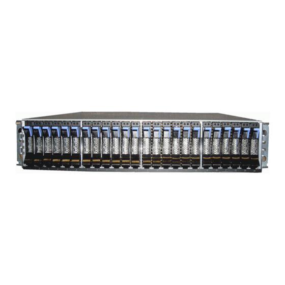
Installing the 5887 disk drive enclosure or setting up a preinstalled 5887 disk drive enclosure Learn how to install a 5887 disk drive enclosure (IBM EXP24S SFF Gen2-bay Drawer) and how to set up a preinstalled 5887 disk drive enclosure (IBM EXP24S SFF Gen2-bay Drawer). -
Page 16: Completing Inventory For The 5887 Disk Drive Enclosure
Record the Electronic Industries Alliance (EIA) locations in your plan. Note: The 5887 disk drive enclosure is two EIA units high. An EIA unit is 44.50 mm (1.75 in) in height. The rack contains three mounting holes for each EIA unit of height. This enclosure, therefore, is 89 mm (3.5 in) high and covers six mounting holes in the rack. - Page 17 Make a note of the lowest EIA unit to be used for the enclosure. b. Use tape, a marker, or a pencil to mark the top mounting hole (A) of the lowest EIA unit. Installing the 5887 disk drive enclosure or setting up a preinstalled 5887 disk drive enclosure...
-
Page 18: Attaching The Mounting Hardware To The Rack
Do not install mismatched hardware by using washers or spacers. If you do not have the correct rails and fittings for your rack, contact your IBM reseller. Important: The rail installation can be completed by one person. However, the installation is easier if one person is positioned at the front of the rack and one person is positioned at the rear of the rack. - Page 19 The enclosure stop (B) points toward the rear of the rack. Figure 4. Opening the rail hinge bracket 6. Locate the two marks that were made previously on the Electronic Industries Alliances (EIA) strips. Installing the 5887 disk drive enclosure or setting up a preinstalled 5887 disk drive enclosure...
- Page 20 The bottom of the rail support ledge appears slightly higher than the U mark on the rack flange. Figure 5. Mounting the rail on the rack 8. At the front of the rail, close the front hinge bracket to secure the rail to the rack cabinet flange. Power Systems: Installing the 5887 disk drive enclosure...
-
Page 21: Installing The 5887 Disk Drive Enclosure Into The Rack
13. Repeat steps 6 on page 5 - 12 for the other rail. Installing the 5887 disk drive enclosure into the rack Learn how to install the 5887 disk drive enclosure into the rack. In addition to related safety information, illustrations of the related hardware components are provided. - Page 22 Figure 8. Sliding the disk drive enclosure into the rack 6. Secure the front of the disk drive enclosure to the rack flanges with one M5 screw (C) in the bottom open holes in each bracket. Power Systems: Installing the 5887 disk drive enclosure...
-
Page 23: Optional: Install Disk Drives In The 5887 Disk Drive Enclosure
3. With the handle in the unlocked position, support the bottom of the disk drive as you align it with the guide rails in the disk drive enclosure. See Figure 10 on page 10 Installing the 5887 disk drive enclosure or setting up a preinstalled 5887 disk drive enclosure... -
Page 24: Connecting The 5887 Disk Drive Enclosure To Your System
Connecting the 5887 disk drive enclosure to your system Learn how to connect the 5887 disk drive enclosure to your system. To connect the 5887 disk drive enclosure to a system with support for a serial-attached SCSI (SAS) disk enclosure, complete the following steps. - Page 25 Figure 11. Mode sticker locations at the rear of the 5887 disk drive enclosure 3. Ensure that all adapters that you need to connect to the 5887 disk drive enclosure are installed in the system or expansion unit. If the adapters are not installed, complete the adapter installation procedure for your system or expansion unit before you continue with this task.
- Page 26 7. Select from the following options: v If the server or expansion unit that you are attaching your 5887 disk drive enclosure to is powered off, continue with step 12. v If the system is powered on, you must do one of the following actions, depending on the supported functions of your operating system: –...
- Page 27 To complete a mode 1 connection of one 5887 disk drive enclosure by using a YO cable to a single SAS adapter, go to step 13. v To complete a mode 1 connection of two 5887 disk drive enclosures by using YO cables to a single SAS adapter, go to step 14.
- Page 28 Figure 13. Mode 1 connection of two 5887 disk drive enclosures by using YO cables to a single SAS adapter Continue with “Connecting cables, power cords, and installing covers” on page 20. 15. Perform the mode 1 connection of one enclosure (A) by using YO cables (B) to a SAS adapter pair (C).
- Page 29 Figure 14. Mode 1 connection of one 5887 disk drive enclosure by using YO cables to a SAS adapter pair Continue with “Connecting cables, power cords, and installing covers” on page 20. 16. Perform the mode 1 connection of two enclosures (A and B) by using YO cables (C and D) to a SAS adapter pair (E).
- Page 30 Figure 15. Mode 1 connection of two 5887 disk drive enclosures by using YO cables to a SAS adapter pair Continue with “Connecting cables, power cords, and installing covers” on page 20. 17. Perform the mode 2 connection of one enclosure (A) by using YO cables (B) to two independent SAS adapters.
- Page 31 Figure 16. Mode 2 connection of one 5887 disk drive enclosure by using YO cables to two independent SAS adapters Continue with “Connecting cables, power cords, and installing covers” on page 20. 18. Perform the mode 2 connection of one enclosure (A) by using X cables (B) to two SAS adapter pairs.
- Page 32 Figure 17. Mode 2 connection of one 5887 disk drive enclosure by using X cables to two SAS adapter pairs Continue with “Connecting cables, power cords, and installing covers” on page 20. 19. Perform the mode 4 connection of one enclosure (A) by using X cables (B) to four independent SAS adapters.
- Page 33 Figure 18. Mode 4 connection of one 5887 disk drive enclosure by using X cables to four independent SAS adapters Figure 19. Labels for SAS adapter cables that show P1 and P2 identifiers Installing the 5887 disk drive enclosure or setting up a preinstalled 5887 disk drive enclosure...
-
Page 34: Connecting Cables, Power Cords, And Installing Covers
3. Route the power cords through the power cord retention brackets (D) for strain relief, as shown in the following figure. Figure 20. Routing the power cords through the cord retention brackets 4. Connect the power cords to the left and right power supplies. Power Systems: Installing the 5887 disk drive enclosure... - Page 35 7. Rotate the cover down until it snaps into place. Make sure that the inside surface of the cover is flush with the chassis. Figure 22. Attaching the side covers 8. Connect the other end of the power cables to the power distribution units (PDUs). Installing the 5887 disk drive enclosure or setting up a preinstalled 5887 disk drive enclosure...
-
Page 36: Completing The 5887 Disk Drive Enclosure Installation
AIX system or AIX logical partition (http://www.ibm.com/support/ knowledgecenter/POWER8/p8hal/pxhal_configdrive_aix.htm). v To configure a disk drive or SSD for use by IBM i, see Configuring a disk drive or solid-state drive for use in an IBM i system or IBM i logical partition (http://www.ibm.com/support/ knowledgecenter/POWER8/p8hal/pxhal_configdrive_ibmi.htm). -
Page 37: Removing The Shipping Bracket On A Preinstalled Enclosure
Learn how to remove the shipping bracket that is used to brace the preinstalled enclosure. There are three parts in the bracket assembly that is used to stabilize the 5887 disk drive enclosure during shipment of the rack that contains the enclosure. The bracket assembly consists of a large bracket that attaches to the rack frame and two smaller brackets that secure the two enclosure services manager (ESM) units. - Page 38 3. To remove the small and large brackets, complete the following steps: a. Loosen the two thumbscrews (A) on the small front brackets below the ESM units. Remove the brackets by lifting them up and away from the ESM units. Power Systems: Installing the 5887 disk drive enclosure...
- Page 39 Using a screwdriver, remove the screw that attaches the large bracket to the left flange of the rack frame. Then, remove the screw that attaches the bracket to right flange. Note: Keep the screws that you remove for later in the procedure. Installing the 5887 disk drive enclosure or setting up a preinstalled 5887 disk drive enclosure...
- Page 40 Slide the large bracket toward the rear of the rack. Lift the bracket with two hands to remove it from the side rails. Tip: Save all of the brackets that you remove for future reinstallation and for shipping of the enclosure that might be required. Power Systems: Installing the 5887 disk drive enclosure...
- Page 41 For one ESM at a time, place your forefingers under the release levers and pinch the terracotta lever tips. Release the levers and swing them into their fully open position. Installing the 5887 disk drive enclosure or setting up a preinstalled 5887 disk drive enclosure...
- Page 42 Figure 27. Opening the ESM release levers c. Moving one ESM at a time, slide the unit into the chassis until it stops. Figure 28. Docking the ESM units Power Systems: Installing the 5887 disk drive enclosure...
- Page 43 5. To dock and secure the power supplies, complete the following steps: a. Moving one power supply at a time, slide the unit approximately 75 mm (3 in) away from the chassis. Installing the 5887 disk drive enclosure or setting up a preinstalled 5887 disk drive enclosure...
- Page 44 For one power supply at a time, rest your right thumb on the terracotta release latch beside the unit handle and your fingertips on the handle. In one motion, squeeze the release latch to the right and swing the handle down into its fully open position. Power Systems: Installing the 5887 disk drive enclosure...
- Page 45 Figure 31. Opening the power supply release handle c. Moving one power supply at a time, slide the unit into the chassis until it stops. Figure 32. Docking the power supplies Installing the 5887 disk drive enclosure or setting up a preinstalled 5887 disk drive enclosure...
-
Page 46: Optional: Install Disk Drives In The Preinstalled 5887 Disk Drive Enclosure
Moving one power supply at a time, swing the unit handle up and into its fully closed position on the release latch. Figure 33. Closing the power supply release handle Optional: Install disk drives in the preinstalled 5887 disk drive enclosure Learn about the disk drives and details on how to install them. -
Page 47: Connecting The Preinstalled 5887 Disk Drive Enclosure To Your System
Connecting the preinstalled 5887 disk drive enclosure to your system Learn how to connect the 5887 disk drive enclosure to your system. To connect the 5887 disk drive enclosure to a system with support for a serial-attached SCSI (SAS) disk enclosure, complete the following steps. - Page 48 Figure 35. Mode sticker locations at the rear of the 5887 disk drive enclosure 3. Ensure that all adapters that you need to connect to the 5887 disk drive enclosure are installed in the system or expansion unit. If the adapters are not installed, complete the adapter installation procedure for your system or expansion unit before you continue with this task.
- Page 49 Note: Adapters are cabled to the enclosure by using ports at the rear of the enclosure. To learn about the enclosure ports that are used in the following options, see Connector locations. Installing the 5887 disk drive enclosure or setting up a preinstalled 5887 disk drive enclosure...
- Page 50 To complete a mode 1 connection of one 5887 disk drive enclosure by using a YO cable to a single SAS adapter, go to step 13. v To complete a mode 1 connection of two 5887 disk drive enclosures by using YO cables to a single SAS adapter, go to step 14.
- Page 51 Note: The single SAS adapter (E) has access to all 48 drive bays. Figure 37. Mode 1 connection of two 5887 disk drive enclosures by using YO cables to a single SAS adapter Continue with “Connecting cables, power cords, and installing side covers on your preinstalled enclosure”...
- Page 52 Figure 38. Mode 1 connection of one 5887 disk drive enclosure by using YO cables to a SAS adapter pair Continue with “Connecting cables, power cords, and installing side covers on your preinstalled enclosure” on page 43. 16. Perform the mode 1 connection of two enclosures (A and B) by using YO cables (C and D) to a SAS adapter pair (E).
- Page 53 Figure 39. Mode 1 connection of two 5887 disk drive enclosures by using YO cables to a SAS adapter pair Continue with “Connecting cables, power cords, and installing side covers on your preinstalled enclosure” on page 43. 17. Perform the mode 2 connection of one enclosure (A) by using YO cables (B) to two independent SAS adapters.
- Page 54 Figure 40. Mode 2 connection of one 5887 disk drive enclosure by using YO cables to two independent SAS adapters Continue with “Connecting cables, power cords, and installing side covers on your preinstalled enclosure” on page 43. 18. Perform the mode 2 connection of one enclosure (A) by using X cables (B) to two SAS adapter pairs.
- Page 55 Figure 41. Mode 2 connection of one 5887 disk drive enclosure by using X cables to two SAS adapter pairs Continue with “Connecting cables, power cords, and installing side covers on your preinstalled enclosure” on page 43. 19. Perform the mode 4 connection of one enclosure (A) by using X cables (B) to four independent SAS adapters.
- Page 56 Figure 42. Mode 4 connection of one 5887 disk drive enclosure by using X cables to four independent SAS adapters Note: Refer to Figure 43 on page 43 for examples of these connections: v The cable that plugs into independent SAS adapter 1 (C) contains a label with the P1 identifier (G).
-
Page 57: Connecting Cables, Power Cords, And Installing Side Covers On Your Preinstalled Enclosure
4. Fit the slot on the top of the cover over the tab on the chassis flange. 5. Rotate the cover down until it snaps into place. Make sure that the inside surface of the cover is flush with the chassis. Installing the 5887 disk drive enclosure or setting up a preinstalled 5887 disk drive enclosure... -
Page 58: Completing The 5887 Disk Drive Enclosure Installation
AIX system or AIX logical partition (http://www.ibm.com/support/ knowledgecenter/POWER8/p8hal/pxhal_configdrive_aix.htm). v To configure a disk drive or SSD for use by IBM i, see Configuring a disk drive or solid-state drive for use in an IBM i system or IBM i logical partition (http://www.ibm.com/support/ knowledgecenter/POWER8/p8hal/pxhal_configdrive_ibmi.htm). - Page 59 (http://www.ibm.com/support/knowledgecenter/POWER8/p8haj/ pxhaj_hsmverify.htm). 3. You have completed the steps to install your 5887 disk drive enclosure. If you were directed here from another procedure, return to that procedure now. Installing the 5887 disk drive enclosure or setting up a preinstalled 5887 disk drive enclosure...
- Page 60 Power Systems: Installing the 5887 disk drive enclosure...
-
Page 61: Reference Information
If your system is running the Linux operating system, type shutdown -h now. v If your system is running the IBM i operating system, type PWRDWNSYS. If your system is partitioned, use the PWRDWNSYS command to power down each of the secondary partitions. Then, use the PWRDWNSYS command to power down the primary partition. -
Page 62: Stopping A System By Using The Hmc
Enhanced+ interface, complete the following steps: 1. You must deactivate all the active logical partitions before powering off the system. To deactivate logical partitions for a specific system, complete the following steps: Power Systems: Installing the 5887 disk drive enclosure... -
Page 63: Stopping An Ibm Powerkvm System
Click OK. Stopping an IBM PowerKVM system You can use the Intelligent Platform Management Interface (IPMI) to stop an IBM PowerKVM system. To stop an IBM PowerKVM system, complete the following steps: 1. Log in to the host as a root user or with sudo authority. - Page 64 E: Eject button v F: Function/Data display v G: Pinhole reset button v H: Decrement button v I: Enter button v J: Increment button 4. Observe the following aspects after pressing the power button: Power Systems: Installing the 5887 disk drive enclosure...
-
Page 65: Starting A System By Using The Asmi
v The power-on light begins to flash faster. v The system cooling fans are activated after approximately 30 seconds and begin to accelerate to operating speed. v Progress indicators, also referred to as checkpoints, appear on the control panel display while the system is being started. -
Page 66: Starting An Ibm Powerkvm System
Starting an IBM PowerKVM system You can use the Intelligent Platform Management Interface (IPMI) to start an IBM PowerKVM system. To start an IBM PowerKVM system, run the ipmitool -I lanplus -H FSP IP -P ipmipassword chassis power on command from a remote system. -
Page 67: Connector Locations For The 5887 Disk Drive Enclosure
Connector locations for the 5887 disk drive enclosure Learn about connector locations for the 5887 disk drive enclosure. Figure 47. Connector locations for the 5887 disk drive enclosure Connector locations for the PCIe Gen3 I/O expansion drawer Learn about connector locations for the PCIe Gen3 I/O expansion drawer (PCIe3 expansion drawer). -
Page 68: Connector Locations For The 8286-41A System
Learn about connector locations for the 8286-41A rack-mounted and stand-alone models. The 8286-41A server provides cable connector locations via a SAS port for disk drive enclosures. Figure 50. Connector locations for the rack-mounted 8286-41A (expanded function) system Power Systems: Installing the 5887 disk drive enclosure... -
Page 69: Connector Locations For The 8286-42A System
Figure 51. Connector locations for the stand-alone 8286-41A (expanded function) system Connector locations for the 8286-42A system Learn about connector locations for the 8286-42A rack-mounted models. The 8286-42A (expanded function) server provides cable connector locations via a SAS port for disk drive enclosures. -
Page 70: Connector Locations For The 8408-E8E System
Connector locations for the 9119-MHE and 9119-MME systems Learn about connector locations for the 9119-MHE and 9119-MME systems. The 9119-MHE and 9119-MME servers provide cable connector locations for the PCIe Gen3 I/O expansion drawer. Power Systems: Installing the 5887 disk drive enclosure... -
Page 71: Connector Locations For Power7 Servers
P1-T1 P1-T2 P1-T3 P1-T4 P1-T5 P1-T6 Figure 54. Connector locations for the 9119-MHE and 9119-MME systems Connector locations for POWER7 servers ® Learn about connector locations for POWER7 servers. Model 8202-E4B connector locations Learn about connector locations on rack-mounted and stand-alone models. Figure 55. -
Page 72: Model 8202-E4C Connector Locations
– The card installed in the C1 slot can contain two PCIe cable ports. However, the C1 slot cannot provide both PCIe and 12X DDR cable ports. – The server contains a SAS port. Power Systems: Installing the 5887 disk drive enclosure... -
Page 73: Model 8202-E4D Connector Locations
Figure 57. Model 8202-E4C connections for expansion units, disk drive enclosures, and PCIe storage enclosures Model 8202-E4D connector locations Learn about connector locations on rack-mounted models. The 8202-E4D server provides cable connector locations for the following enclosures: v Support for expansion units, as shown in the following figure, is as follows: –... -
Page 74: Model 8205-E6B Connector Locations
Support for expansion units, as shown in the following figure, is as follows: – The card installed in the C1 slot can contain two 12X double data rate (DDR) cable ports. However, the C1 slot cannot provide both 12X DDR and PCIe cable ports. Power Systems: Installing the 5887 disk drive enclosure... -
Page 75: Model 8205-E6D Connector Locations
– The card installed in the C8 slot can contain two 12X DDR cable ports. However, the C8 slot cannot provide both 12X DDR and PCIe cable ports. – The port card type installed in the C1 slot can differ from the port card type installed in the C8 slot. –... -
Page 76: Model 8231-E1C Connector Locations
Support for PCIe storage enclosures, as shown in the following figure, is as follows: – The card installed in the C1 slot can contain one PCIe cable port. – The server contains a SAS port. Power Systems: Installing the 5887 disk drive enclosure... -
Page 77: Model 8231-E2B Connector Locations
Figure 64. Model 8231-E1D or 8268-E1D connections for disk drive enclosures and PCIe storage enclosures Model 8231-E2B connector locations Learn about connector locations on rack-mounted models. The 8231-E2B server provides cable connector locations for the following enclosures: v Support for disk drive enclosures, as shown in the following figure, is as follows: –... -
Page 78: Model 8231-E2D Connector Locations
– The server cannot support both 12X DDR cable ports and PCIe cable ports at the same time. – The server contains a serial-attached SCSI (SAS) port. v Support for disk drive enclosures, as shown in the following figure, is as follows: – The server contains a SAS port. Power Systems: Installing the 5887 disk drive enclosure... -
Page 79: Model 8233-E8B Connector Locations
Figure 68. Model 8231-E2D connections for expansion units and disk drive enclosures v Support for PCIe storage enclosures, as shown in the following figure, is as follows: – The card installed in the C1 slot can contain one PCIe cable port, and the card installed in the C8 slot can contain one PCIe cable port. -
Page 80: Model 8246-L1S Connector Locations
Figure 71. Model 8246-L1S connector locations Model 8246-L1T connector locations Learn about connector locations. Figure 72. Model 8246-L1T connector locations Model 8246-L2S connector locations Learn about connector locations. Figure 73. Model 8246-L2S connector locations Power Systems: Installing the 5887 disk drive enclosure... -
Page 81: Model 8246-L2T Connector Locations
Model 8246-L2T connector locations Learn about connector locations. Figure 74. Model 8246-L2T connector locations Model 8248-L4T, 8408-E8D, or 9109-RMD connector locations Learn about connector locations. The 8248-L4T, 8408-E8D, and 9109-RMD servers provide cable connector locations for the following enclosures: v Support for expansion units, as shown in the following figure, is as follows: –... -
Page 82: Model 9117-Mmb Or 9179-Mhb Connector Locations
Figure 75. Model 8248-L4T, 8408-E8D, or 9109-RMD connector locations for expansion units, disk drive enclosures, and PCIe storage enclosures Model 9117-MMB or 9179-MHB connector locations Learn about connector locations. Figure 76. Model 9117-MMB or 9179-MHB connector locations Power Systems: Installing the 5887 disk drive enclosure... -
Page 83: Model 9117-Mmc Or 9179-Mhc Connector Locations
Model 9117-MMC or 9179-MHC connector locations Learn about connector locations. Figure 77. Model 9117-MMC or 9179-MHC connector locations Model 9117-MMD or 9179-MHD connector locations Learn about connector locations. The 9117-MMD and 9179-MHD servers provide cable connector locations for the following enclosures: v Support for expansion units, as shown in the following figure, is as follows: –... - Page 84 Figure 78. Model 9117-MMD or 9179-MHD connector locations for expansion units, disk drive enclosures, and PCIe storage enclosures Power Systems: Installing the 5887 disk drive enclosure...
-
Page 85: Notices
This information was developed for products and services that are offered in the USA. This material may be available from IBM in other languages. However, you may be required to own a copy of the product or product version in that language in order to access it. -
Page 86: Privacy Policy Considerations
All statements regarding IBM's future direction or intent are subject to change or withdrawal without notice, and represent goals and objectives only. All IBM prices shown are IBM's suggested retail prices, are current and are subject to change without notice. Dealer prices may vary. -
Page 87: Trademarks
IBM, the IBM logo, and ibm.com are trademarks or registered trademarks of International Business Machines Corp., registered in many jurisdictions worldwide. Other product and service names might be trademarks of IBM or other companies. A current list of IBM trademarks is available on the web at Copyright and trademark information at www.ibm.com/legal/copytrade.shtml. - Page 88 This product has been tested and found to comply with the limits for Class A Information Technology Equipment according to European Standard EN 55022.
- Page 89 Warning: This is a Class A product. In a domestic environment this product may cause radio interference in which case the user will be required to take adequate measures. IBM Taiwan Contact Information: Electromagnetic Interference (EMI) Statement - Korea Notices...
- Page 90 Um dieses sicherzustellen, sind die Geräte wie in den Handbüchern beschrieben zu installieren und zu betreiben. Des Weiteren dürfen auch nur von der IBM empfohlene Kabel angeschlossen werden. IBM übernimmt keine Verantwortung für die Einhaltung der Schutzanforderungen, wenn das Produkt ohne Zustimmung von IBM verändert bzw.
-
Page 91: Class B Notices
Properly shielded and grounded cables and connectors must be used in order to meet FCC emission limits. Proper cables and connectors are available from IBM-authorized dealers. IBM is not responsible for any radio or television interference caused by unauthorized changes or modifications to this equipment. - Page 92 This product is in conformity with the protection requirements of EU Council Directive 2004/108/EC on the approximation of the laws of the Member States relating to electromagnetic compatibility. IBM cannot accept responsibility for any failure to satisfy the protection requirements resulting from a non-recommended modification of the product, including the fitting of non-IBM option cards.
- Page 93 Um dieses sicherzustellen, sind die Geräte wie in den Handbüchern beschrieben zu installieren und zu betreiben. Des Weiteren dürfen auch nur von der IBM empfohlene Kabel angeschlossen werden. IBM übernimmt keine Verantwortung für die Einhaltung der Schutzanforderungen, wenn das Produkt ohne Zustimmung von IBM verändert bzw.
-
Page 94: Terms And Conditions
Permissions for the use of these publications are granted subject to the following terms and conditions. Applicability: These terms and conditions are in addition to any terms of use for the IBM website. Personal Use: You may reproduce these publications for your personal, noncommercial use provided that all proprietary notices are preserved. - Page 96 Part Number: 00RW813 Printed in USA GI11-9909-02...