
Related Manuals for Toa F-122CU


Summary of Contents for Toa F-122CU
- Page 1 Rev. A INSTRUCTION MANUAL CEILING SPEAKER SYSTEM F-122CU Please follow the instructions in this manual to obtain the optimum results from this unit. We also recommend that you keep this manual handy for future reference.
-
Page 2: Table Of Contents
TABLE OF CONTENTS 1. SAFETY PRECAUTIONS 2. GENERAL DESCRIPTION 3. FEATURES 4. NOMENCLATURE AND DIMENSIONS 5. MOUNTING HARDWARE INSTALLATION 6. WIRING 6.1. Using the Speaker in UL1480 Category UUMW ... 9 6.2. Using the Speaker in UL1480 Category UEAY only 6.2.1. -
Page 3: Safety Precautions
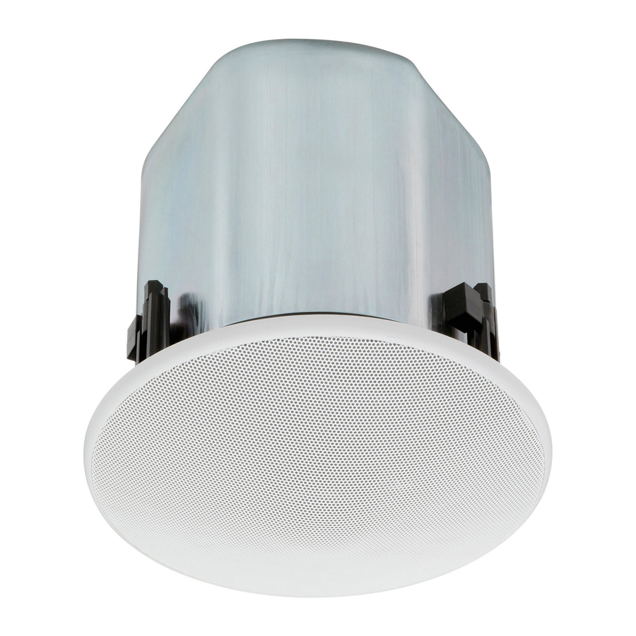
2. GENERAL DESCRIPTION The F-122CU is a flush-mounted ceiling speaker that offers a wide frequency range of high-quality sound output. Use of its supplied mounting hardware and optional HY-TB1 Tile Bar Bridge permits it to be versatilely mounted to match a wide range of applications and installation locations. -
Page 4: Features
3. FEATURES • Bass-reflex speaker system designed to provide a wide frequency range and high power handling capability. • Wide-dispersion flush-mount ceiling speaker design employs unique acoustic construction to realize a wide area of coverage. Uniform sound output levels are achievable not only directly under the speaker, but also over a wide radius. -
Page 5: Mounting Hardware Installation
5. MOUNTING HARDWARE INSTALLATION Before mounting the speaker, determine the most appropriate method for the existing ceiling structure. Be sure to use an optional HY-TB1 Tile Bar Bridge in combination with the supplied ceiling reinforcement ring. [Installation view on Drop Ceilings] Because the bridge rails are 603 mm (23 installation. - Page 6 Step 1. Cut a ø200 mm (7 Use the supplied paper pattern to position and trace the hole. Step 2. Install the HY-TB1 in the ceiling. Loosen the two reinforcement ring mounting screws in each tie-plate to the point that they do not fall out of their holes.
- Page 7 Step 3. Place the supplied reinforcement ring on the ceiling panel. Fold the reinforcement ring in half* and insert it through the mounting hole in the ceiling panel, then open it with its tabs facing up. Place the ring on the ceiling panel aligning it with the mounting hole.
- Page 8 Step 5. Attach a safety wire to prevent the speaker from accidentally falling. To attach, tie one end of the supplied safety wire around the speaker's safety wire hook, and tie its snap ring around the installed HY-TB1 or a solid structure. Note When there is no gap between the bridge rails and the ceiling panel, to secure the safety wire, tie the wire around a solid structure (pipe, building frame, etc.).
-
Page 9: Wiring
6. WIRING 6.1. Using the Speaker in UL1480 Category UUMW Choke bracket Cover plate Conduit fitting Detachable input connector Connector cover After completing the speaker cable connection, turn the connector cover in the direction indicated by the arrow, and fix the cover with 2 screws. Remove the choke bracket and the cover plate from the speaker. -
Page 10: Using The Speaker In Ul1480 Category Ueay Only
6.2. Using the Speaker in UL1480 Category UEAY only 6.2.1. Wiring through hard or flexible conduit Note The choke bracket equipped with the speaker has not been evaluated by UL, for conduit connection and UL514B Standard. Flexible conduit of 3/8 or 1/2 inch trade size and the UL514B conduit fitting of the same trade size can also be used. -
Page 11: Wiring With Naked Cables
6.2.2. Wiring with naked cables Choke bracket Retighten the screw to fix the speaker cable. Connector cover After completing the speaker cable connection, turn the connector cover in the direction indicated by the arrow, and fix the cover with 2 screws. Loosen the screw to allow the speaker cable to pass through. -
Page 12: Cable Connection To Input Connector
7. CABLE CONNECTION TO INPUT CONNECTOR Recommended cable types • Solid copper wire: ø1.0 – ø1.6 mm (equivalent to AWG 18 – 14) • Stranded copper wire: 0.75 – 2.5 mm (equivalent to AWG 18 – 14) Step 1. Loosen the 2 cover mounting screws, and rotate the connector cover in the direction indicated by the arrow in the figure at right. -
Page 13: Speaker Installation
8. SPEAKER INSTALLATION Caution Before mounting, check to be sure that the speaker's 3 mounting tabs are turned inside the unit as shown in the figure. If turned outward, the speaker cannot be inserted through the mounting hole. Step 1. Insert the speaker through the mounting hole till it contacts the ceiling panel. - Page 14 Step 3. Set the input power. Turn the input selector switch (on the unit's front) to set it to the desired input impedance. (Factory-preset to 170 Ω.) Note Setting positions "8 Ω" and "16 Ω" can be used in UL1480 Category UEAY only. Step 4.
-
Page 15: Removing The Speaker For Maintenance
9. REMOVING THE SPEAKER FOR MAINTENANCE 9.1. Detaching the Front Grille Turn the front grille counterclockwise to full stop, then lightly pull it downward. The front grille employs a double-locking system. If the grille cannot be detached when lightly pulled downward, it likely has not yet been fully rotated back to the detachment position. -
Page 16: Repainting The Speaker
11. INPUT OVERLOAD PROTECTION FUNCTION The F-122CU features an internal input overload protection circuitry. If an extremely high input level is fed to the unit, the protection circuitry automatically cuts off the signal to the speaker element. -
Page 17: Safety Agency Compliance
16VP Signaling Speaker The F-122CU's front-mounted rotary switch permits selection of speaker handling power (wattage) on 25 V or 70 V line operation or low impedance (8 Ω or 16 Ω) operation. Depending on the switch settings, the unit complies with the different UL Categories as follows. -
Page 18: Specifications
13. SPECIFICATIONS Enclosure Rated Input Power Handling Capacity Impedance Frequency Response Speaker Component UL Code Mounting Hole Input Terminal Usable Cable Finish Dimensions Weight Note: The design and specifications are subject to change without notice for improvement. • Accessories Front grille ... 1 Ceiling reinforcement ring ... - Page 19 Printed in Indonesia 533-06-090-20...