
Related Manuals for Texas Instruments THS3001


Summary of Contents for Texas Instruments THS3001
- Page 1 THS3001 High Speed Current Feedback Operational Amplifier Evaluation Module User’s Guide March 1999 Mixed-Signal Products SLOU021A...
- Page 2 IMPORTANT NOTICE Texas Instruments and its subsidiaries (TI) reserve the right to make changes to their products or to discontinue any product or service without notice, and advise customers to obtain the latest version of relevant information to verify, before placing orders, that information being relied on is current and complete. All products are sold subject to the terms and conditions of sale supplied at the time of order acknowledgement, including those pertaining to warranty, patent infringement, and limitation of liability.
- Page 3 Related Documentation From Texas Instruments THS3001 HIGH-SPEED CURRENT-FEEDBACK OPERATIONAL AMPLIFIER (literature number SLOS217) This is the data sheet for the THS3001 operational amplifier integrated circuit that is used in the THS3001 evaluation module. FCC Warning This equipment is intended for use in a laboratory test environment only. It...
-
Page 5: Table Of Contents
THS3001 EVM PC Board Layout – Component Side 2–3 THS3001 EVM PC Board Layout – Back Side 2–4 THS3001 Rev. A EVM Component Placement Silkscreen and Solder Pads 2–5 THS3001 Rev. A EVM PC Board Layout – Component Side 2–6 THS3001 Rev. -
Page 7: General Information
General Information This chapter details the Texas Instruments (TI ) THS3001 high-speed operational amplifier evaluation module (EVM), SLOP130. It includes a list of EVM features, a brief description of the module illustrated with a pictorial and a schematic diagram, EVM specifications, details on connecting and using the EVM, and a discussion on high-speed amplifier design considerations. -
Page 8: Features
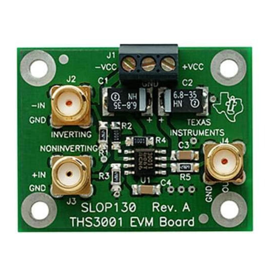
— just connect it to power, a signal source, and a load (if desired). Two versions of the THS3001 EVM are available. The original appears in Figure 1–1 and the Rev. A version appears in Figure 1–2. -
Page 9: Ths3001 Rev. A Evaluation Module
INVERTING NONINVERTING The THS3001 EVM is equipped with both noninverting and inverting inputs. The noninverting input is set for a gain of 2 and the inverting input is set for a gain of 1. Each input is terminated with a 50- resistor to provide correct line impedance matching (Figure 1–3 for original version and Figure 1–4 for Rev. -
Page 10: Ths3001 Rev. A Evm Schematic
Rev. A Noninverting Even though the THS3001 is a current-feedback amplifier, the gain of the EVM can easily be changed to support a particular application by simply changing the ratio of resistors R1, R4, and R5 (R1, R2, and R4 for Rev. A) as described... -
Page 11: Ths3001 Evm Specifications
............Continuous power dissipation at T For complete THS3001 amplifier IC specifications and parameter measurement information, and additional application information, see the THS3001 data sheet, TI Literature Number SLOS217. -
Page 12: Using The Ths3001 Evm
7) Verify the output signal on the oscilloscope. Note: The signal shown on an oscilloscope with a 50- input impedance will ½ the actual THS3001 amplifier IC output voltage. This is due to the voltage division between the output resistor (R2) and the oscilloscope input impedance. -
Page 13: Ths3001 Evm Performance
1.5 THS3001 EVM Performance Figure 1–5 shows the typical frequency response of the THS3001 EVM using the noninverting input (G = 2). Typical values show a – 3-dB bandwidth of 340 MHz with a 15-V power supply and 260 MHz with a 5-V power supply. -
Page 14: General High-Speed Amplifier Design Considerations
General High-Speed Amplifier Design Considerations 1.6 General High-Speed Amplifier Design Considerations The THS3001 EVM layout has been designed and optimized for use with high-speed signals and can be used as an example when designing THS3001 applications. Careful attention has been given to component selection, grounding, power supply bypassing, and signal path layout. -
Page 15: Reference
This chapter includes a parts list and PCB layout illustrations for the THS3001 EVM and the THS3001 Rev. A EVM. Topic THS3001 High-Speed Operational Amplifier EVM Parts List THS3001 EVM Board Layouts ........ -
Page 16: Ths3001 Evm Board Layouts
PCB, THS3001 EVM 2.2 THS3001 EVM Board Layouts Board layout examples of the THS3001 EVM PCB are shown in the following illustrations. They are not to scale and appear here only as a reference. Figure 2–1. THS3001 EVM Component Placement Silkscreen and Solder Pads –VCC... -
Page 17: Ths3001 Evm Pc Board Layout - Component Side
THS3001 EVM Board Layouts Figure 2–2. THS3001 EVM PC Board Layout – Component Side Figure 2–3. THS3001 EVM PC Board Layout – Back Side Reference... -
Page 18: Ths3001 Rev. A High-Speed Operational Amplifier Evm Parts List
PCB, THS3001 Rev. A EVM 2.4 THS3001 Rev. A EVM Board Layouts Board layout examples of the THS3001 Rev. A EVM PCB are shown in the following illustrations. They are not to scale and appear here only as a reference. -
Page 19: Ths3001 Rev. A Evm Pc Board Layout - Component Side
THS3001 Rev. A EVM Board Layouts Figure 2–5. THS3001 Rev. A EVM PC Board Layout – Component Side Rev. A Figure 2–6. THS3001 Rev. A EVM PC Board Layout – Back Side Rev. A Reference... - Page 20 Reference...