
Related Manuals for Hoshizaki IM-200BAC


Summary of Contents for Hoshizaki IM-200BAC
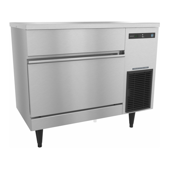
- Page 1 Service Manual Self-Contained Cuber Models IM-200BAC Number: 73244 hoshizakiamerica.com Issued: 9-3-2019...
- Page 2 Hoshizaki provides this manual primarily to assist qualified service technicians in the service of the appliance. Should the reader have any questions or concerns which have not been satisfactorily addressed, please call, send an e-mail message, or write to the Hoshizaki Technical Support Department for assistance. Phone: 1-800-233-1940; (770) 487-2331 Fax: 1-800-843-1056;...
-
Page 3: Table Of Contents
IMPORTANT This manual should be read carefully before the appliance is serviced. Read the warnings and guidelines contained in this manual carefully as they provide essential information for the continued safe use, service, and maintenance of the appliance. Retain this manual for any further reference that may be necessary. CONTENTS Important Safety Information .................... -
Page 4: Important Safety Information
Important Safety Information Throughout this manual, notices appear to bring your attention to situations which could result in death, serious injury, damage to the appliance, or damage to property. WARNING Indicates a hazardous situation which could result in death or serious injury. - Page 5 WARNING, continued • Children should be properly supervised around this appliance. • Do not climb, stand, or hang on the appliance or allow children or animals to do so. Serious injury could occur or the appliance could be damaged. • Do not use combustible spray or place volatile or flammable substances near the appliance.
-
Page 6: Construction And Water/Refrigeration Circuit Diagram
I. Construction and Water/Refrigeration Circuit Diagram A. Construction 1. Air-Cooled Model (BAC) Top Panel Top Insulation Top Sheet Front Sheet Side Panel Front Frame Front Panel Slope Door Lower Front Cover Louver Air Filter Front View (Outside) Power Supply Cord Rear Panel Rear View (Outside) - Page 7 Evaporator Water Pan Evaporator Thermistor Actuator Motor Control Board Thermistor Thermostatic Inlet Water Valve Expansion Valve Hot Gas Valve Water Tank Control Switch Pump Motor Fuse Holder Drain Pan Fan Motor Water Tank Drain Pipe Bin Control Front View (Inside) Control Box High Pressure Switch...
-
Page 8: Water/Refrigeration Circuit Diagram
B. Water/Refrigeration Circuit Diagram 1. Air-Cooled Model (BAC) Inlet Water Valve Thermostatic Expansion Valve Evaporator Evaporator Thermistor Water Pan Water Tank Water Pump Condenser Heat Exchanger Hot Gas Fan Motor Valve Strainer Compressor Drier Water Circuit Refrigerant Circuit... -
Page 9: Sequence Of Operation And Service Diagnosis
II. Sequence of Operation and Service Diagnosis A. Sequence of Operation Flow Chart Control Board 1. 30-Sec. 3. Freeze Cycle 2. Harvest Cycle Cycle Startup • Max. freeze time: 50 min. (CB Setting 6) • HGV: If CBT≤32°F (0°C) (CB Setting 74), Steps Cycle HGV repeatedly energizes 40 sec./de-... -
Page 10: Service Diagnosis
B. Service Diagnosis WARNING • The appliance should be diagnosed and repaired only by qualified service personnel to reduce the risk of death, electric shock, serious injury, or fire. • Risk of electric shock. Use extreme caution and exercise safe electrical practices. •... - Page 11 1. Operation Diagnosis 1) Startup Cycle: Turn on the power supply. Move the control switch to the "ICE" position. "on" appears on CB display. HGV energizes and Comp/AMD 30-sec. delay timer. Note: • CB "on" display remains on unless the 10.5VAC power supply to CB CN1 is interrupted.
- Page 12 2) Harvest Cycle: Comp 30-sec. delay timer terminates, 20-sec. WV delay timer starts, Comp and AMD (opening) energize. HGV continues. 20-sec. WV delay timer terminates, WV energizes. WV 24 sec. on timer starts. AMD de-energizes when AMPS activates at water pan assembly fully open position. Once ET reaches 41°F (5°C), HGV de-energizes, FM and AMU (closing) energize.
- Page 13 3) Freeze Cycle: AMPS activated (water pan assembly completely closed). WV energizes. 74-sec. or 37-sec. timer starts. Comp and FM continue. Evaporator cooling. Once 74-sec. or 37-sec. timer terminates, WV de-energizes and PM energizes. a) AMU Diagnosis: AMU completes its rotation and AMPS is activated. If AM does not rotate up, check for 115VAC at CB CN5 #1 (O) to neutral (W).
- Page 14 Freeze Termination: CB monitors time after ET temperature ≤ 32°F (0°C). CB terminates freeze cycle when the following equation is satisfied: temp. (absolute value) × time (min.) = (absolute value of CB Setting 2) × (CB Setting 3) Using default settings, freeze cycle is terminated when: temp.
-
Page 15: Control Board Check
C. Control Board Check Before replacing CB that does not show a visible defect and that you suspect is bad, always conduct the following check procedure. This procedure will help you verify your diagnosis. Always choose a white (W) neutral wire to establish a good neutral connection when checking voltages. -
Page 16: Bin Control Check
D. Bin Control Check 1. Bin Control Check This appliance uses a lever-actuated proximity switch to control the ice level in the storage bin. No adjustment is required. To check BC, follow the steps below. 1) Turn off the power supply. 2) Remove the front panel, then move the control switch to the "OFF"... - Page 17 BC from the bin control bracket and move to the front of the icemaker for cleaning. 5) Remove the actuator paddle from the switch mount. See Fig. 1. 6) Wipe down BC with a mixture of 1 part of Hoshizaki "Scale Away" and 25 parts of warm water. Rinse the parts thoroughly with clean water.
-
Page 18: Evaporator Thermistor Check
E. Evaporator Thermistor Check To check thermistor resistance, follow the steps below. 1) Turn off the power supply. 2) Remove the front panel. Move the control switch to the "OFF" position. 3) Remove the control box cover. 4) Remove the thermistor from the evaporator. 5) Immerse the thermistor sensor portion in a glass containing ice and water for 2 or 3 min. -
Page 19: Diagnosis Table
G. Diagnosis Table First see "III.F. Error Codes." If there are no recorded errors, refer to the table below. No Ice Production - Possible Cause 1. Power Supply a) Off, blown fuse, or tripped breaker. b) Not within specifications. 2. Fuse (Control Box) a) Blown. - Page 20 Low Ice Production - Possible Cause Long Harvest Cycle 1. Evaporator a) Scaled up. 2. Control Board a) Thermistor connection loose (K3). b) Defective. 3. Evaporator (Cube Control) a) Loose, disconnected, or defective. Thermistor See "II.E. Evaporator Thermistor Check" 4. Hot Gas Valve a) Erratic or closed.
- Page 21 Large-Hole Cubes - Possible Cause (Also see III.G.1. Dimple Diameter") 1. Condenser a) Dirty condenser or air filter. 2. Fan Motor a) Defective. 3. Refrigerant Charge a) Low. Large-Hole Cubes - Possible Cause (Also see III.G.1. Dimple Diameter") 4. Icemaker Location a) Insufficient clearance.
-
Page 22: Freeze-Up Check List
H. Freeze-Up Check List Freeze-Up Check List IM Series Please Complete When Diagnosing a Freeze-Up, Refrigerant Leak, or Low Charge Technical Support Fax #: 770-487-3360 Make Copies And Use As Needed Model #___________________________ Serial # ____________________Install Date____________Freeze-Up Date___________ List model and manufacture of bin or dispenser__________________________. Date appliance was last cleaned:__________. -
Page 23: Controls And Adjustments
III. Controls and Adjustments A. Control Board • A Hoshizaki exclusive control board is employed in IM series appliances. • All models are pretested and factory adjusted. NOTICE • Fragile, handle very carefully. • The control board contains integrated circuits, which are susceptible to failure due to static discharge. - Page 24 1. Control Board Layout • CN16 Connector Actuator Motor Position Sensor (Hall IC) Input • CN11 Connector Bin Control Input • CN13 Connector Evaporator (Cube Control) Thermistor Input • CN10 Connector • CN9 Connector Compressor Start DC Relay Drive Output Display Output •...
-
Page 25: Control Board Buttons
B. Control Board Buttons The control board features RESET, SERVICE 1, and SERVICE 2 Buttons 1. RESET Button • Press briefly to go to initial harvest cycle. • Press and hold for 3 seconds to enter control board setting mode. For details about control board settings, see "III.E. Control Board Model Code Setting."... -
Page 26: Control Board Settings
C. Control Board Settings NOTICE Failure to maintain factory settings may adversely affect performance and warranty coverage. For more information, contact your Hoshizaki Service Center. 1) With "on" in display, press and hold the "RESET" button for 3 seconds. Display changes to "1". - Page 27 Control Board (CB) Setting Menu IM-200BAC Category No. Item Range Default Water 12 Freeze Cycle Water Supply Time 1: Partial Drain (CB 0 to 90 sec. Supply, Setting 14) (1 sec. increments) continued Freeze Cycle Water Supply Time 1: Full Drain (CB Setting 13 Water Temperature Correction Value +0 to +20°C...
- Page 28 Control Board (CB) Setting Menu IM-200BAC Category No. Item Range Default Other 21 Stackable Bin Control Yes=1; No=0 Allows for stacked units to be controlled through one bin control. DO NOT ADJUST 22 Refrigeration Circuit Cycling when Bin Full On=1; Off=0...
- Page 29 Control Board (CB) Setting Menu IM-200BAC Category No. Item Range Default Water Tank See Ranges Below See If control board thermistor temperature is above the water Ice Control Defaults tank ice control lower temperature setting (CB Setting 74) Below and equal to or less than the water tank ice control upper...
-
Page 30: Control Board Information Display
Lower (Control Board Setting 13). Current Condenser Thermistor Temperature °C Not Applicable to IM-200BAC Last Completed Freeze Cycle Time 0 to 99 min. Freeze cycles interrupted by bin control shutdown or the "RESET" button are not recorded. - Page 31 Control Board Information Display History Cleared by Pressing and Holding SERVICE 1 and SERVICE 2 Buttons Simultaneously for 5 Sec. when Item Value No. Item Description is Displayed? Error Log For example, E5 (most Displays up to 5 errors with the most recent error recent), E4, E3, E2, E1 first.
-
Page 32: Control Board Model Code Setting
0, 1, 2, 3, 4, 5, 6, 7, 8, 9, A, B, C, D, E, F. When a valid model code is displayed, the dot in the bottom right of the display turns on. For IM-200BAC, set model code to "0A". -
Page 33: Error Codes
0, 1, 2, 3, 4, 5, 6, 7, 8, 9, A, B, C, D, E, F. When a valid model code is displayed, the dot in the bottom right of the display turns on. For IM-200BAC, set model code to "0A". - Page 34 Press the "RESET" button to reset. detection temperature (Control Board Setting 36), error is displayed but unit continues to operate. Note: IM-200BAC does not utilize a water regulating valve, therefore Ed error will not occur.
-
Page 35: Quick Adjustments
G. Quick Adjustments 1. Dimple Diameter The factory set dimple diameter is 3/16" (5 mm). NOTICE! Do not decrease the dimple diameter below 3/16" (5 mm). a) To increase dimple diameter: 1) Remove front panel. 2) Press the "SERVICE 1" button to view the current freeze cycle termination temperature setting. - Page 36 2. Ice Clarity In hard water conditions, white ice may be produced. In such cases, install a water filter and/or water softener, then follow the instructions below. 1) Move the control switch to the "OFF" position, then turn off the power supply. 2) Remove the front panel.
-
Page 37: Refrigeration Circuit And Component Service Information
IV. Refrigeration Circuit and Component Service Information WARNING • This appliance should be diagnosed and repaired only by qualified service personnel to reduce the risk of death, electric shock, serious injury, or fire. • Move the control switch to the "OFF" position and turn off the power supply. Place the disconnect in the "OFF"... - Page 38 2. Brazing WARNING • R-404A itself is not flammable at atmospheric pressure and temperatures up to 176°F (80°C). • R-404A itself is not explosive or poisonous. However, when exposed to high temperatures (open flames), R-404A can be decomposed to form hydrofluoric acid and carbonyl fluoride both of which are hazardous.
-
Page 39: Component Service Information
5) Disconnect the gauge manifold hose from the vacuum pump and attach it to a refrigerant service cylinder. Remember to loosen the connection and purge the air from the hose. For the required refrigerant charge, see the nameplate. Hoshizaki recommends only virgin refrigerant or reclaimed refrigerant which meets ARI Standard 700 (latest edition) be used. -
Page 40: Maintenance
V. Maintenance The maintenance schedule below is a guideline. More frequent maintenance may be required depending on water quality, the appliance's environment, and local sanitation regulations WARNING • Only qualified service technicians should service the appliance. • To reduce the risk of electric shock, do not touch the control switch or plug with damp hands. -
Page 41: Preparing The Appliance For Periods Of Non-Use
VI. Preparing the Appliance for Periods of Non-Use NOTICE • During extended periods of non-use, extended absences, or in sub-freezing temperatures, follow the instructions below to reduce the risk of costly water damage. • To prevent damage to the water pump, do not leave the control switch in the "WASH"... - Page 42 4) Allow the icemaker water supply line to drain by gravity. 5) Attach compressed air or carbon dioxide supply to the icemaker water supply line drain valve. 6) Move the control switch to the "ICE" position. 7) Blow the icemaker water supply line out using compressed air or carbon dioxide. 2.
-
Page 43: Disposal
VII. Disposal The appliance contains refrigerant and must be disposed of in accordance with applicable national, state, and local codes and regulations. Refrigerant must be recovered by properly certified service personnel. -
Page 44: Technical Information
VIII. Technical Information We reserve the right to make changes in specifications and design without prior notice. A. Specification and Performance Data Sheets 1. IM-200BAC Specification Sheet AC SUPPLY VOLTAGE 115/60/1 AMPERAGE 7.5 A (5 Min. Freeze AT 104°F / WT 80°F) -
Page 45: Wiring Diagram
B. Wiring Diagram 1. IM-200BAC...