Advertisement
Available languages
Available languages
Quick Links
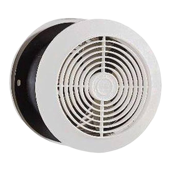
MODEL 512N
ROOM-TO-ROOM FAN
1. All electrical connections must be in accordance with local codes,
ordinances, or Canadian Electrical codes. If you are unfamiliar with
methods of installing electrical wiring, secure the services of a quali-
fied electrician.
2. To avoid motor bearing damage and/or noisy and unbalanced impel-
lers, keep drywall spray, construction dust, etc. off power unit.
1. Plan installation. Fan will install in walls up to 5 1/8" (130.2 mm) thick.
For walls less than 4 1/2" (114.3 mm) thick, a trim board frame for
spacing is required (see Step 12). Fan can be controlled by a wall
switch or speed control (available separately).
2. Carefully cut out fan openings and switch box opening (FIG. 1).
FIG. 1
SWITCH OR
SPEED CONTROL
Be sure to measure and mark center of fan opening on opposite wall
before cutting out either opening.
WHEN CUTTING OR DRILLING INTO WALL BE CAREFUL NOT TO
CUT EXISTING ELECTRICAL WIRING.
3. Remove wiring box from fan.
4. Determine desired air flow direction (FIG. 2).
FIG. 2
GRILLE
BRACKET TAB
FAN HOUSING
DISCONNECT ELECTRICAL POWER TO OUTLET YOU ARE TAPPING
INTO BEFORE MAKING ELECTRICAL CONNECTIONS.
5. Feed electrical cable to switch and fan. Feed cable through wall open-
ing on "inlet" side of fan and into fan housing (FIG. 3).
6. Remove knockout on wiring box. Fasten electrical cable to wiring box
with proper connector for type of wire used. Provide 6" (152.4 mm)
leads inside box for electrical connections.
WIRING BOX
GREEN OR BARE WIRE
WHITE WIRES
COVER
BLACK
WIRES
FIG. 3
DISCONNECT ELECTRICAL POWER SUPPLY BEFORE SERVICING FAN.
Do not turn on the fan when starting a fire in a fireplace or wood stove
until the damper is thoroughly warm and fully open. Turning the fan on
too soon may draw smoke and flue gases into the room. Wait until the
fire is well established.
Always unplug the fan motor before servicing the fan. The motor bear-
ings on this fan are lifetime lubricated and will never need oiling.
INSTALLATION INSTRUCTIONS
INSTALL THE FAN
FAN
WALL OUTLET
CAUTION
WARNING
FAN HOUSING FLANGE
MOUNTING BRACKET
AIRFLOW DIRECTION
(INLET)
MOUNTING BRACKET
WARNING
FAN HOUSING
USE AND CARE
3. Disconnect electrical power supply before installing or servicing fan.
4. Do not turn this fan on when lighting your fireplace or wood stove. The
fan may draw flue gases and smoke into the room. Wait until the fire
is well established before turning on the fan.
7. Make electrical connections. Connect black to black, white to white,
and bare or green wire to box using green ground screw.
8. Position fan housing in wall. Install wiring box and cover.
9. Hold fan housing in wall and drill two 3/16" (4.8 mm) pilot holes
through center of two slots in mounting flange (FIG. 4). Use slots in
flange which line up with mounting bracket openings in fan housing.
FIG. 4
MOUNTING
BRACKET
10. Install mounting brackets from inside of fan housing and pull them
tightly against back of wall. Make sure tab on bracket is engaged in
fan housing (FIG. 2).
11. Insert screws through mounting flange and tighten mounting brackets
firmly against wall.
12. For walls less than 4 1/2" (114.3 mm) thick, frame out fan housing so
that housing is recessed 1/8" (3.2 mm) to 1/4" (6.4 mm) (FIG. 5).
FIG. 5
GRILLE
If fan housing is not flush with edge of wall material, lay a thin bead of
plaster or patching compound along edge of housing to fill gap between
housing and wall (FIG. 6).
FIG. 6
PLASTER
WALL
13. Spin grilles onto mounting studs. Turn on power and check operation
of fan. Tighten grille flush against wall, but do not distort grilles. Bend
grille bracket if necessary to make grille flush with wall.
Clean the fan blade and motor every six months by removing the grille,
unplugging the motor, and gently vacuuming the fan blade and motor.
Clean the grille in warm, soapy water. Use a mild detergent, such as a
dishwashing liquid. DO NOT USE ABRASIVE CLOTHS, STEEL WOOL
OR SCOURING POWDERS.
30040120
Broan-NuTone Canada Inc.
1140 TriStar Drive
Mississauga, Ontario L5T 1H9
FAN HOUSING
WIRING BOX
PANELING
WALL
1/8" (3.2 mm)
to
1/4" (6.4 mm)
FRAME
FAN HOUSING
WALL
FAN HOUSING
GRILLE
BRACKET
99045055A
Advertisement

Related Manuals for Broan 512N


Summary of Contents for Broan 512N
- Page 1 MODEL 512N ROOM-TO-ROOM FAN Broan-NuTone Canada Inc. 1140 TriStar Drive Mississauga, Ontario L5T 1H9 INSTALLATION INSTRUCTIONS 1. All electrical connections must be in accordance with local codes, 3. Disconnect electrical power supply before installing or servicing fan. ordinances, or Canadian Electrical codes. If you are unfamiliar with 4.
- Page 2 MODÈLE 512N VENTILATEUR INTERPIÈCES Broan-NuTone Canada Inc. 1140 TriStar Drive Mississauga, Ontario L5T 1H9 DIRECTIVES D'INSTALLATION 1. Tous les raccordements électriques doivent se conformer aux ordon- 3. Débranchez l`alimentation électrique avant d`installer le ventilateur ou nances et codes locaux ou au code canadien de l`électricité. Si vous ne d`en faire l`entretien.