
Related Manuals for Fujitsu MB95100 Series


Summary of Contents for Fujitsu MB95100 Series
- Page 1 Fujitsu Microelectronics Europe MCU-AN-395002-E-V10 Application Note F²MC-8FX FAMILY 8-BIT MICROCONTROLLER MB95100 SERIES EMULATOR HW SETUP APPLICATION NOTE...
-
Page 2: Revision History
MB2146-09 – Installation Guide Revision History Revision History Date Issue 2004-10-12 V1.0; M. Vogel This document contains 23 pages. MCU-AN-395002-E-V10 - 2 - © Fujitsu Microelectronics Europe GmbH... -
Page 3: Warranty And Disclaimer
Product or parts thereof, if the Product is returned to Fujitsu Microelectronics Europe GmbH in original packing and without further defects resulting from the customer´s use or the transport. -
Page 4: Table Of Contents
Setting Breakpoints ..............21 4.3.3 Types of breakpoints and how to set.......... 22 4.3.4 Trace Windows................22 4.3.5 Display format for trace data ............23 4.3.6 Saving setup file for the Emulator..........23 MCU-AN-395002-E-V10 - 4 - © Fujitsu Microelectronics Europe GmbH... -
Page 5: Introduction
Chapter 1 Introduction 1 Introduction This installation guide will help you setting up the MB2146-09 BGM ADAPTER with the MB2146-301 or MB2146-303 MCU Board for Fujitsu 8FX-microcontroller and its usage with 8bit-Softune Workbench V30L29 or higher. © Fujitsu Microelectronics Europe GmbH... -
Page 6: Hardware Requirements
Do only supply 5 volts DC to MB2146-401 evaluation board. Power supply is directly connected to MCU board if jumper settings (JP3 & JP4) on evaluation board are set to 5V. Higher voltage may damage MCU board, Evaluation board and BGM adapter! MCU-AN-395002-E-V10 - 6 - © Fujitsu Microelectronics Europe GmbH... -
Page 7: Setting Up The Emulation System
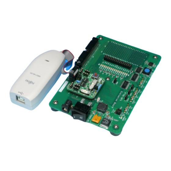
Connect the adapter between the host machine and the user system so that the adapter can serve as an emulator under control of the host machine. Evaluation board Figure 1: System Configuration Figure 2: Configuration overview © Fujitsu Microelectronics Europe GmbH - 7 - MCU-AN-395002-E-V10... -
Page 8: Bgm Adapter
When plugging the user interface connector, align its index mark (pin no. 1) with the adapter interface connector's counterpart. Figure 4: Connection to the User System MCU-AN-395002-E-V10 - 8 - © Fujitsu Microelectronics Europe GmbH... -
Page 9: Adapter Interface Specifications
Tool reset generation methods and reset "L" pulse width: 1. Set the micorocontroller’s user power from OFF to ON (power-on reset). The reset remains in effect for about 16 to 70 ms after the microcontroller’s user power is supplied. © Fujitsu Microelectronics Europe GmbH - 9 - MCU-AN-395002-E-V10... -
Page 10: Mcu Board
Position the boards correctly without letting the incorrect insertion prevention keys interfere with each other and plug connectors together completely. MCU board Evaluation board Figure 6: Connection of MCU board and Evaluation board MCU-AN-395002-E-V10 - 10 - © Fujitsu Microelectronics Europe GmbH... -
Page 11: Jumper Settings And Switches On Mcu Board
10. Set the jumper plug S1 (1+2) to CB. 11. Mount the main clock oscillator (refer chapter 3.3.3) 12. Mount the sub clock oscillator (refer chapter 3.3.3, not required) Figure 7: switch and jumper setting on MCU board © Fujitsu Microelectronics Europe GmbH - 11 - MCU-AN-395002-E-V10... -
Page 12: How To Mount Oscillator On Mcu Board
Capacitor mounting socket* Capacitor mounting socket* Crystal oscillator mounting socket Ceramic Crystal resonator oscillator *Capacitors are not required if a ceramic resonator is used! Figure 8: Crystal or ceramic oscillator mounting MCU-AN-395002-E-V10 - 12 - © Fujitsu Microelectronics Europe GmbH... -
Page 13: Evaluation Board
(MOD pin connected to GND -> run mode) 6. Set LED jumper plugs JP1 and JP2 to connect I/O port to LEDs on evaluation board Supply only Figure 9: jumper settings on evaluation board 5V DC! © Fujitsu Microelectronics Europe GmbH - 13 - MCU-AN-395002-E-V10... -
Page 14: Setting Up The Emulation Software
4.2.1 Procedure for Setting Setup File by Setup Wizard This section explains the procedure for making an additional setup file for the emulator. 1. Right click on ‘Debug’ in project-window and choose [Add Setup] -> [New…]. MCU-AN-395002-E-V10 - 14 - © Fujitsu Microelectronics Europe GmbH... - Page 15 2. Enter a name for the new setup file and click [OK]. 3. Follow the steps in the upcoming setup wizard. Click [Next] to go to the next window. 4. Select ‘Emulator Debugger’ as Debug Type. © Fujitsu Microelectronics Europe GmbH - 15 - MCU-AN-395002-E-V10...
- Page 16 MB2146-09 – Installation Guide Chapter 4 Setting up the Emulation Software 5. Select ‘MB2146-09’ as ICE type. 6. Choose ‘USB’ for Device Name. 7. Enter oscillator frequency in MHz. (In this case 4MHz) MCU-AN-395002-E-V10 - 16 - © Fujitsu Microelectronics Europe GmbH...
- Page 17 9. Activate ‘Auto load when starting debug’ option by checking the box. Here a batch file executed before or after load can be specified (not in this case). 10. Choose ‘Select All’ under Select setting item. © Fujitsu Microelectronics Europe GmbH - 17 - MCU-AN-395002-E-V10...
- Page 18 12. The added setup file appears in the ‘project’-window. The setup file, which starts up when the [Start debug] command in the [Debug] menu is executed, is displayed in blue. Double-clicking the setup file, the Debugger starts up according to its setup information. MCU-AN-395002-E-V10 - 18 - © Fujitsu Microelectronics Europe GmbH...
-
Page 19: Optimization Of Response Speed During Debugging
If a break occurs immediately after changing the system clock mode by the user program, no clock up is performed during oscillations stabilization wait state. Clock up will be performed when oscillations are stabilized. © Fujitsu Microelectronics Europe GmbH - 19 - MCU-AN-395002-E-V10... -
Page 20: Executing Program
4. Reset MCU before executing the program. 5. Run your user program. 6. To stop user program click the marked button. MCU-AN-395002-E-V10 - 20 - © Fujitsu Microelectronics Europe GmbH... -
Page 21: Setting Breakpoints
Click the left circle of the source window to set the breakpoint “X”. The yellow line indicates the current position of the instruction pointer (IP). Note: The IP value is the same as the PC value. © Fujitsu Microelectronics Europe GmbH - 21 - MCU-AN-395002-E-V10... -
Page 22: Types Of Breakpoints And How To Set
The trace buffer is structually a ring-shaped, so data is overwritten automatically from the beginning of the sequence buffer when the trace buffer is full. 1. Select [Trace] from the [View] menu to open the trace window. MCU-AN-395002-E-V10 - 22 - © Fujitsu Microelectronics Europe GmbH... -
Page 23: Display Format For Trace Data
Select the [Save...] command from the [File] menu to save the setup file for the emulator in the Save dialog. The setup file can be saved only in debug mode. © Fujitsu Microelectronics Europe GmbH - 23 - MCU-AN-395002-E-V10...