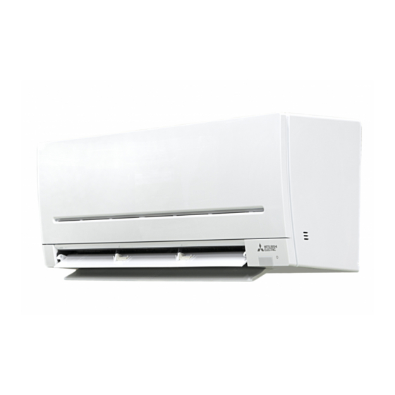
Mitsubishi Electric MSZ-AP15VG Installation Manual
Hide thumbs
Also See for MSZ-AP15VG:
- Operating instructions manual (177 pages) ,
- Installation manual (172 pages) ,
- Service manual (44 pages)
Advertisement
Quick Links
MSZ-AP15VG
MSZ-AP20VG
INSTALLATION MANUAL
INSTALLATIONSANLEITUNG
NOTICE D'INSTALLATION
INSTALLATIEHANDLEIDING
MANUAL DE INSTALACIÓN
MANUALE PER L'INSTALLAZIONE
ΙΡΙΔΙ
Σ
ΣΗΣ
MANUAL DE INSTALAÇÃO
INSTALLATIONSHÅNDBOG
INSTALLATIONSANVISNING
Р
С
А М Н АЖ
INSTRUKCJA MONTA U
INSTALLASJONSHÅNDBOK
ASENNUSOPAS
INSTALAČN
RUČKA
NÁVOD NA INŠTALÁCIU
TELE T SI K
IK NYV
NAMESTITVENI RIROČNIK
MANUAL DE INSTALARE
PAIGALDUSJUHEND
MONT
AS ROKASGR MATA
MONTAVIMO VADOVAS
RIRUČNIK A OSTAVLJANJE
UPUTSTVO ZA UGRADNJU
English
Deutsch
Français
Español
Italiano
ικ
Português
Dansk
Svenska
Norsk
Suomi
Češt na
Magyar
Rom n
Eesti
Latviski
L etuv ška
Hrvatski
Srpski
Advertisement

Summary of Contents for Mitsubishi Electric MSZ-AP15VG
- Page 1 MSZ-AP15VG MSZ-AP20VG English INSTALLATION MANUAL Deutsch INSTALLATIONSANLEITUNG Français NOTICE D’INSTALLATION INSTALLATIEHANDLEIDING Español MANUAL DE INSTALACIÓN Italiano MANUALE PER L’INSTALLAZIONE ικ ΙΡΙΔΙ Σ ΣΗΣ Português MANUAL DE INSTALAÇÃO Dansk INSTALLATIONSHÅNDBOG Svenska INSTALLATIONSANVISNING Р С А М Н АЖ INSTRUKCJA MONTA U Norsk INSTALLASJONSHÅNDBOK...
-
Page 2: Table Of Contents
FOR INSTALLER Required Tools for Installation CONTENTS Phillips screwdriver 4 mm hexagonal wrench Level Flare tool for R32, R410A 1. BEFORE INSTALLATION ........1 When installing multi units, Scale Gauge manifold for R32, R410A 2. INDOOR UNIT INSTALLATION ......4 refer to the installation Utility knife or scissors Vacuum pump for R32, R410A... - Page 3 *7 Breaker Indoor/outdoor Indoor unit Outdoor unit Rated Voltage Frequency Power supply *2 Gas / Liquid capacity connecting wire *2 MSZ-AP15VG 4-core ø9.52 / 6.35 mm 230 V 50 Hz 3-core 1.0 mm² (0.8 mm) MSZ-AP20VG MUZ-AP20VG 10 A 810 g 1.0 mm²...
- Page 4 1-4. INSTALLATION DIAGRAM ACCESSORIES PARTS TO BE PROVIDED AT YOUR SITE Check the following parts before installation. (A) Indoor/outdoor unit connecting wire*1 <Indoor unit> (B) Extension pipe (1) Installation plate (C) Wall hole sleeve (2) Installation plate xing screw 4 25 mm (D) Wall hole cover (3) Wireless remote controller...
-
Page 5: Indoor Unit Installation
2. INDOOR UNIT INSTALLATION 2-1. FIXING OF INSTALLATION LATE 2-4. I E FORMING AND DRAIN I ING Find a structural material (such as a stud) in the wall and x installation plate Pipe Forming lace the drain hose below the refrigerant piping. (1) hori ontally by tightening the xing screws (2) rmly. -
Page 6: Outdoor Unit Installation
3. OUTDOOR UNIT INSTALLATION 3-1. CONNECTING WIRES FOR OUTDOOR UNIT Flaring tool Copper pipe Burr 1) Open the service panel. Spare reamer 2) Loosen terminal screw, and connect indoor/outdoor unit connecting wire (A) Pipe cutter from the indoor unit correctly on the terminal block. Be careful not to make mis-wiring. -
Page 7: Purging Procedures, Leak Test, And Test Run
3- . CONNECTING THE INTERFACE/CONNECTOR CABLE TO THE AIR CONDITIONER Connect the INTERFACE/CONNECTOR CABLE to the Indoor electronic control .C. board of the air conditioner with the connecting cable. Cutting or extending the connecting cable of the INTERFACE/CONNECTOR CABLE results in defects in connecting. Do not bundle the connecting cable together with power supply cord, Indoor/outdoor connecting wire, and/or earth wire. -
Page 8: Relocation And Maintenance
4-2. TEST RUN 4-3. AUTO RESTART FUNCTION 1) Insert power supply plug into the power outlet This product is equipped with an auto restart function. When the power and/or turn on the breaker. supply is stopped during operation, such as during blackouts, the function 2) Press the E.O.


