Table of Contents
Advertisement
Quick Links
Your new tool has been engineered and manufactured to WEN's highest standards for dependability,
ease of operation, and operator safety. When properly cared for, this product will supply you years
of rugged, trouble-free performance. Pay close attention to the rules for safe operation, warnings,
and cautions. If you use your tool properly and for intended purpose, you will enjoy years of safe,
reliable service.
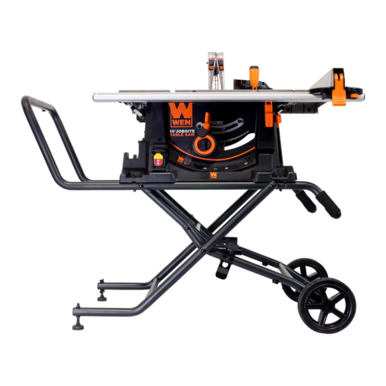
10˝ JOBSITE TABLE SAW
IMPORTANT:
NEED HELP? CONTACT US!
Have product questions? Need technical support?
Please feel free to contact us at:
800-232-1195
techsupport@wenproducts.com
WENPRODUCTS.COM
Model # 3720
bit.ly/wenvideo
(M-F 8AM-5PM CST)
Advertisement
Table of Contents

Related Manuals for Wen 3720


Summary of Contents for Wen 3720
- Page 1 IMPORTANT: Your new tool has been engineered and manufactured to WEN’s highest standards for dependability, ease of operation, and operator safety. When properly cared for, this product will supply you years of rugged, trouble-free performance. Pay close attention to the rules for safe operation, warnings, and cautions.
- Page 2 Know Your Table Saw Assembly and Adjustments Operation Maintenance Exploded View & Parts List Warranty TECHNICAL DATA Model Number: 3720 Motor: 120 V, 60 Hz, 15A 4400 RPM No Load Speed: 10-in. Carbide Tipped Blade Blade Size: 5/8 in. Arbor Size: Number of Teeth: 3-9/16 in.
-
Page 3: General Safety Rules
GENERAL SAFETY RULES Safety is a combination of common sense, staying alert and knowing how your item works. SAVE THESE SAFE- TY INSTRUCTIONS. WARNING: To avoid mistakes and serious injury, do not plug in your tool until the following steps have been read and understood. - Page 4 GENERAL SAFETY RULES 15. DO NOT OVERREACH. Keep proper footing and balance at all times. Wear oil-resistant rubber-soled foot- wear. Keep the floor clear of oil, scrap, and other debris. 16. MAINTAIN TOOLS PROPERLY. ALWAYS keep tools clean and in good working order. Follow instruc- tions for lubricating and changing accessories.
- Page 5 SPECIFIC RULES FOR TABLE SAWS 9. REMOVE ALL ACCESSORIES FROM THE TABLE. Before transporting the saw, remove all accessories (miter gauge, rip fence..). Failure to do so can result in an accident causing possible serious personal injury. 10. NEVER USE RIP FENCE AS A CUT-OFF GAUGE when crosscutting. Move the rip fence out of the way. 11.
-
Page 6: Electrical Information
ELECTRICAL INFORMATION DOUBLE INSULATION Double insulation is a concept in safety in electric power tools that eliminates the need for the usual three-wire grounded power cord. All exposed metal parts are isolated from the internal metal motor components with protect- ing insulation. -
Page 7: Know Your Table Saw
KNOW YOUR TABLE SAW Extension table lock/release lever Front rip fence rail with ruler Bevel angle adjustment wheel Feed table extention Blade height adjustment lock Anti-kickback fingers assembly Blade height adjustment handwheel Blade guard assembly Stand release latch Rip fence assembly Power Switch with safety key Rip fence lock lever Reset... -
Page 8: Assembly And Adjustments
ASSEMBLY AND ADJUSTMENTS ASSEMBLY OF FOLDING STAND (Fig. 1) 1. Insert both handles (A) into the large U-shaped bracket (B). Make sure the screw hole in each handle matches the screw hole on the U-shaped bracket. Align the screw holes and secure the handles using a small pan head screw. -
Page 9: Adjusting Riving Knife
ASSEMBLY AND ADJUSTMENTS Note: Before folding the stand, remove all workpieces from the table. Remove and securely store all loose accessories such as the miter gauge, rip fence, blade guard, anti-kickback fingers and push stick. Lower saw blade below the table top. Fig.4 shows the stand in its folded position with all accessories in their storage areas. - Page 10 ASSEMBLY AND ADJUSTMENTS ALIGNING RIVING KNIFE IMPORTANT: If riving knife is correctly mounted yet it is not perfectly centered with the blade, proceed with the following adjustment. 1. Using a straight edge (Fig 8), check if the riving knife is aligned with the blade.
- Page 11 ASSEMBLY AND ADJUSTMENTS MOUNTING RIP FENCE ON TABLE AND ADJUSTMENTS 1. Position the front of the rip fence (A, Fig 12) on the front rail (B, Fig 12). Lower the back end of the rip fence on the rear rail. Check to make sure the rip fence slides freely on the rails.
- Page 12 ASSEMBLY AND ADJUSTMENTS ADJUSTING THE EXTENDABLE EXTENSION TABLE The extension table allows the user to increase the length of the table for greater ripping capacity (maximum 25 in.). To use the extension table: 1. Unlock or remove the rip fence from the table. 2.
- Page 13 ASSEMBLY AND ADJUSTMENTS ADJUSTING THE BEVEL ANGLE INDICATOR If the blade is at a 90° angle and the bevel indicator (A, Fig 20) does not indicate 0° on the scale, an adjustment can be made: 1. Place a combination square (A, Fig.19) on the table and up against the flat portion of the blade (B, Fig.19).
- Page 14 ASSEMBLY AND ADJUSTMENTS INSTALLING/CHANGING BLADE WARNING - Disconnect power cord from power source before installing/changing blade. 1. Uninstall the blade guard and anti-kickback fingers assembly from the riving knife. Then remove the table insert to gain access to the blade arbor. 2.
-
Page 15: Cross Cutting
OPERATION CROSS CUTTING Cross cutting requires the use of the miter gauge to position and guide the work piece. Place the work piece against the miter gauge and advance both the miter gauge and work piece toward the saw blade keeping your hands and fingers clear of the path of the blade. - Page 16 OPERATION USING A DADO BLADE SET (OPTIONAL) AND DADO INSERT Dadoing is cutting a rabbet or a wide groove into the work. Most dado head sets are made up of two outside blades and four or five inside cutters, as shown in Fig. 25. Various combination of blades and cutters are used to cut grooves from 1/8 in.
- Page 17 EXPLODED VIEW & PARTS LIST...
- Page 18 EXPLODED VIEW & PARTS LIST...
- Page 19 3720-073 Angle adjustment wheel 3720-028 Compression spring 3720-074 Square nut 3720-029 Linkage pivot 3720-075 Bevel indicator 3720-030 End cap 3720-076 Bushing - driving rod 3720-031 Rear rail 3720-077 Bracket - driving rod 3720-033 End cap 3720-078 Lock washer 3720-034 Crank wheel knob...
- Page 20 EXPLODED VIEW & PARTS LIST Item# Stock # Description Item# Stock # Description 3720-092 Cord snapping ring 3720-224 Bolt 3720-093 Bolt 3720-225 Baffle 3720-094 Store holder 3720-226 Bearing sleeve 3720-095 Over-load protection 3720-227 Armature assembly 3720-096 Power cord 3720-228 Fan...
- Page 21 906 3720-906 Small spacer 3720-607 Screw 907 3720-907 Anti-loose nut 3720-608 Washer 908 3720-908 Middle stand 3720-701 Screw 909 3720-909 Round tube end cap 3720-702 Washer 910 3720-910 Rear stand 3720-703 Rip fence indicator 911 3720-911 Wing nut 3720-704 Rip fence label...
-
Page 22: Limited Two Years Warranty
LIMITED TWO YEARS WARRANTY WEN Products is committed to build tools that are dependable for years. Our warranties are consistent with this commitment and our dedication to quality. LIMITED WARRANTY OF WEN CONSUMER POWER TOOLS PRODUCTS FOR HOME USE GREAT LAKES TECHNOLOGIES, LLC (“Seller”) warrants to the original purchaser only, that all WEN con- sumer power tools will be free from defects in material or workmanship for a period of two (2) years from date of purchase.