Advertisement
Quick Links
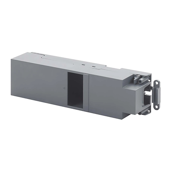
Control Module Box AP 118
Product- and Applications Description
The AP 118 Control Module Box with a height of 41 mm
is designed for installation in a false ceiling, in a raised
floor, directly on a wall or in an installation channel or
raceway. The Control Module Box is affixed with screws
at the two ends of the housing.
The Control Module Box offers one mounting location for
these modules:
5WG1 260-4AB23
5WG1 510-2AB23
5WG1 512-4AB23
5WG1 520-2AB23
5WG1 521-4AB23
5WG1 525-2AB23
The mounted module is connected to the bus line via a
bus terminal block.
The AP 118 Control Module Box provides wiring space
with room for two connectors for PE and N conductors.
This allows for secure connection of the PE and N con-
ductors of the cables inserted into the AP 118 Control
Module Box.
For strain relief, cables can be secured at the entrance to
the wiring space.
Line voltage supply and load conductors are terminated
at the terminals of the mounted modules.
Application Programs
Requires no application programs
Siemens AG
Infrastructure and Cities Sector, Building Technologies
Control Products and Systems
P. O. Box 10 09 53, D-93009 Regensburg
Binary input, quadruple,
AC/DC 12...230V
Binary output (relay), 2 x 10A
Load switch (relay), 1 x 16A
Blind / shutter actuator, 1 x 6A
Blind / shutter actuator, 2 x 6A
Universal dimmer, 1 x 250VA
© Siemens AG 2017
Subject to change without further notice.
Example of Application
figure 1: Example of Application
Installation instructions
∂ The Control Module Box may be used for permanent
interior installations, for mounting in dry rooms, in
false ceilings, raised floors, and installation channels or
raceways.
Υ
DANGER
∂ The Control Module Box must be mounted and com-
missioned by an authorized electrician.
∂ A safety disconnection of the Control Module Box must
be possible.
∂ For planning and construction of electric installations,
the relevant guidelines, regulations and standards of
the respective country are to be considered.
AP 118, page 1 / 6
GAMMA instabus
Technical Product-Information
August 2017
5WG1 118-4AB01
Technical Manual
Update: http://www.siemens.com/gamma
2.4.2.11/1
Advertisement

Related Manuals for Siemens AP 118


Summary of Contents for Siemens AP 118
- Page 1 Product- and Applications Description Example of Application The AP 118 Control Module Box with a height of 41 mm is designed for installation in a false ceiling, in a raised floor, directly on a wall or in an installation channel or raceway.
-
Page 2: Technical Data
∂ relative humidity (non-condensing): 5 % bis 93 % figure 2a: Mounting CE norm ∂ complies with low voltage regulations Technical Manual AP 118, page 2 / 6 Siemens AG Infrastructure and Cities Sector, Building Technologies Update: http://www.siemens.com/gamma © Siemens AG 2017 Control Products and Systems Subject to change without further notice. - Page 3 (A4). - Fasten the screws (A3) to secure the lid. figure 4: mounting / dismounting of RS/RL modules Siemens AG AP 118, page 3 / 6 Technical Manual Infrastructure and Cities Sector, Building Technologies Control Products and Systems ©...
- Page 4 B2 RL module B3 Type label (with space for physical address of the module) B4 Mounting location for RS / RL module in AP 118 Control Module Box or AP 641 Room Control Box B5 Bus connection module with bus connection pins...
- Page 5 6: dismounting an RS module ∂ Mounting of an RL module: - AP 118: Remove the lid of the Control Module Box. - Insert the RL module (B2) into the hinge (B13) of the mounting location (B4). The terminals (B14) point away from the insertion point for the bus terminal (B11).
-
Page 6: Dimension Drawing
∂ The operating instructions must be handed over to the client. ∂ Any faulty device is to be sent together with a return delivery note of the local Siemens office. figure 11: Connecting/disconnecting mains and load ∂ For any technical questions, please consult: circuit &...