Siemens UL 489 Operating Instructions Manual
Hide thumbs
Also See for UL 489:
- Quick start manual (12 pages) ,
- Instruction sheet (12 pages) ,
- Application manual (96 pages)
Table of Contents
Advertisement
Low Voltage Insulated Case Circuit Breaker
UL489 Circuit Breaker
Operating Instructions
Hazardous voltage.
Will cause death, serious personal injury, or equipment damage.
Turn off and lock out all power supplying this equipment before working on this device.
923 99994 174
DANGER
Catalog No.: CBIM-01001-0119
3ZX1812-0WL20-1AN2
Advertisement
Table of Contents

Related Manuals for Siemens UL 489


Summary of Contents for Siemens UL 489
- Page 1 Low Voltage Insulated Case Circuit Breaker UL489 Circuit Breaker Operating Instructions Catalog No.: CBIM-01001-0119 DANGER Hazardous voltage. Will cause death, serious personal injury, or equipment damage. Turn off and lock out all power supplying this equipment before working on this device. 923 99994 174 3ZX1812-0WL20-1AN2...
- Page 2 Should further information be desired or should particular problems arise, which are not covered sufficiently for the purchaser’s purposes, the matter should be referred to the local Siemens sales office. The contents of this instruction manual shall not become part of or modify any prior or existing agreement, commitment or relationship.
-
Page 3: Table Of Contents
Contents Overview ........1-1 Frame sizes / dimension drawings . - Page 4 10 Reset the reclosing lockout and the Bell Alarm ..10-1 Breaker mounted key lock ..... . 15-2 Resetting the Bell Alarm .
- Page 5 23 Plexiglas breaker cover ......23-1 Exchanging the stab tip ..... . . 24-14 Catalog numbers .
-
Page 6: Overview
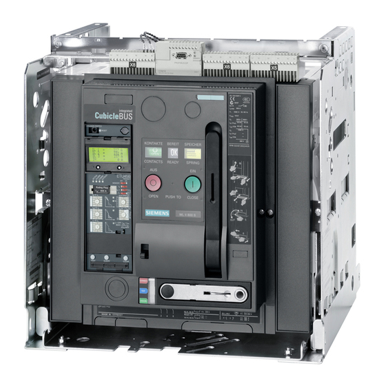
Overview Circuit Breaker Arc chute (page 24-5) Carrying handle Identification tags Motor disconnect switch (option) (page 13-3) Circuit breaker type label (page 2-1) Spring charge indicator (page 6-7) Mechanical "CLOSE" button Rated current value Racking pictogram (10) Make-break operations counter (option) ... -
Page 7: Cradle
Cradle (with optional accessories) (14) (11) (12) (13) (10) Arc chute cover (option) Hole for crane hook Arc vent openings Shutter (option) Locking device shutter (standard for shutters) Mutual mechanical circuit breaker interlocking (option) Locking provision for guide rail Door interlock (option) Locking device in OPEN position (option) (10) Cradle mounted locking device against closing the circuit breaker in disconnect position (option) -
Page 8: Labels
X9-6 X5-6 X5-10 X5-4 X5-8 RESET TRIPPED Siemens Industry, Inc X9-13 Made in Czech Republic / Assembled in USA 240 VAC , 10 A / 125 VDC , 0.5 A / 24 VDC , (BELL ALARM SHOWN TRIPPED) Grand Prairie, TX 75050, USA... -
Page 9: Frame Designation
Frame designation WLS2D316 Type of circuit breaker (WL) Siemens interrupting class Frame size Draw-out or fixed mounted circuit breaker No. of poles Maximum rated continuous current Trip unit designation N450101000001 WLN., WLS., WLH., WLL., WLF., WLM. Type Catalog number Can be used in the following types of circuit breakers Regulatory approvals on a separate label 2 –... -
Page 10: Rating Plug Label
Rating Plug label Catalog number Rated current of the circuit breaker Regulatory approvals on a separate label Cradle type label Catalog number Rated current and voltage of the cradle UL listing mark Circuit breakers that can be used with this cradle Sales order, production order, cradle identification number A second type label is attached to the baseplate inside the cradle or on one of its side walls. -
Page 11: Standard Specifications
Circuit breakers to be installed in dusty or damp locations must be appropriately enclosed. The circuit breaker frame and the trip units are in conformity with the standards: - UL 489 - NAVAL use according UL 489 Suppl. SB - CSA C22.2 No. 5-02 The cradles are in conformity with the standards: - UL 489 - CSA C22.2 No. -
Page 12: Packing And Lifting
Packing and Lifting Unpacking Unpack the circuit breaker and inspect it for damage. If the circuit breaker or cradle is to be installed at a later date: they may only be stored and redispatched in the original packing. NOTICE Equipment Damage. Placing the circuit breaker on its rear side may cause damage to the finger cluster assemblies. -
Page 13: Lifting With A Crane
Lifting with a crane DANGER Heavy Equipment. Improper lifting will cause death, serious personal injury, or equipment/property damage. Never lift a circuit breaker or cradle above personnel. Follow instructions for use of lifting bar assembly. Use OSHA/NIOSH approved crane equipment and personal protection equipment for lifting/moving the circuit breakers and cradles. Circuit Breaker Cradle ... -
Page 14: Lifting With A Lifting Bar Assembly
Lifting with a Lifting Bar Assembly DANGER Heavy Equipment. Improper lifting will cause death, serious personal injury, or equipment/property damage. Never lift a circuit breaker or cradle above personnel. Follow instructions for use of lifting bar assembly. Use OSHA/NIOSH approved crane equipment and personal protection equipment for lifting/moving the circuit breakers and cradles. -
Page 15: Lifting The Circuit Breaker
4.4.2 Lifting the circuit breaker Catalog No Lifting beam for circuit breaker and cradle WLLFT Portable hoist for use with the lifting beam WLHOIST 4 – 4... -
Page 16: Installation
Installation DANGER Hazardous voltage. Will cause death, serious personal injury, or equipment damage. Turn off and lock out all power supplying this equipment before working on this device. DANGER Heavy Equipment. Improper lifting will cause death, serious personal injury, or equipment/property damage. Never lift a circuit breaker, fuse carriage, or cradle above personnel. -
Page 17: Mounting
Mounting 5.1.1 Mounting position WARNING Heavy Equipment Can cause serious personal injury. Use care when racking the breaker into the disconnect position. When a draw-out circuit breaker is mounted tilting toward the front side, it is possible that the circuit breaker may slide out on the rails. 5 –... -
Page 18: Mounting On Horizontal Surface - Mounting Tolerances
Mounting on horizontal surface - 5.1.2 Mounting tolerances The circuit breaker must be mounted on a rigid, level surface, capable of supporting the weight of the breaker, cradle, and associated busbar components. The maximum amount of offset in the mounting plane is 3/64“ (1mm). Fixed-mounted breaker ... - Page 19 Fixed-mounted circuit breaker with 4 captive nuts for: FS I / II: bolts M8 + washers kit catalog no. WLMETRC FS III: bolts M10 + washers kit catalog no. WLMETRC3 Alternatively with bolts, washers and nuts: FS I / II: “...
-
Page 20: Cubicle And Ventilation
5.1.3 Cubicle and ventilation Upper ventilation opening Insulating liner use NEMA GPO-3, min. 0.094“ thick or comparable material Lower ventilation opening Insulating liner Minimal cubicle dimensions Cubicle ventilation dimensions Frame Frame Interrupting rating Bottom size Class Width W1 Height H Depth D1 Width W2 Depth D2... - Page 21 The installation space dimensions given on the type label ensure the necessary clearances to grounded metal surfaces up to 600 V AC according to UL 489. Additional guidelines for applications without compartmentalization as cubicles or for positioning of parts within the cubicle are given below.
- Page 22 Dimensions for phase barriers made of insulating material (mm) Class Operating voltage not possible not possible 1) Valid with nominal cubicle width only FS I, II: 22“ FS III: 32“ 2) Measured from top surface of arc chutes Dimensions for dead metal barriers (mm) Class Operating voltage...
- Page 23 5.1.3.3 Draw-out circuit breaker Without arc chute cover Minimum vertical clearance Minimum clearance on either side Minimum horizontal rear-side clearance Dimensions (mm) Class v, c v, c v, c Operating voltage S, H, L Consult Technical Support 1) Measured from top surface of arc chutes 2) Valid with unblocked arcing space on top only ...
- Page 24 1) Switchgear 2) Arc chute cover Minimum vertical clearance Minimum clearance on either side Minimum rear-side clearance Dimensions (mm) Class v, c v, c v, c Operating voltage 1) Measured from top surface of arc chutes 2) Openings in top of cradle side wall shall not be blocked, side clearance of 30 mm required. ...
-
Page 25: Main Terminal Connections
Main terminal connections Frame sizes / dimension drawings (page 7-1) For main terminal dimensions of individual frame sizes, refer to: The main terminals and connectors are intended for busbar connection with NEMA hole patterns. The number and size of the busbars con- nected to the circuit breaker must be selected per UL 891 in order to meet the design and test requirements according to UL 891 depending on the rated current, defined by the rating plug. -
Page 26: Vertical Connections For Fixed Mount Circuit Breakers
5.2.3 Vertical connections for fixed mount circuit breakers Fixed mount circuit breaker Connection to Line/Load Side terminal with vertical connectors Frame Size Number of busbars Busbar cross-section Number of holes nmax 800 A / 1200 A 1 - 3 3“ x ¼“ 800 A / 1600 A 1 - 3 2000 A... - Page 27 Frame size I NOTE The bus connectors are different for the three poles. Installation as shown below. 8 Nm 71 lb-in Size 10 mm 70 Nm 50 ft-lb Hex head screw M6x20 Threaded plate 2xM12 Vertical adapter Riser Socket head cap screw M12x90 Hex head screw M6x35 Socket head cap screw M12x50 Different offset...
- Page 28 Frame size II Installing support for the lower contacts Size 5 mm 5 Nm 45 ft-lb Size 5 mm 10 Nm 89 lb-in All lower screws Size 5 mm 8 Nm 71 lb-in Frame size II, 3200 A Frame size II, 800-2000 A 5 –...
- Page 29 Attaching vertical adapter Construction Style A Size 10 mm 70 Nm 50 ft-lb Construction Style B 0640-6 70 Nm 50 ft-lb 5 – 14...
- Page 30 Alignment of vertical adapters NOTE Center the vertical adaptor of the center pole (phase B) on the copper connector of adapter and tighten it. Shift the vertical adaptors (7) of the outer poles (phase A & B) outwards until the specified distance of 5 1/4" is reached and tighten them. Hex-head screw...
- Page 31 Frame size III Attaching vertical adapter Size 10 mm 70 Nm 50 ft-lb Alignment of vertical adapters Hex-head screw M12 x 80 Belleville washer Washer M12 nut Vertical adapter 5 – 16...
-
Page 32: Front Connections
5.2.3.2 Catalog numbers Fixed-mounted circuit breaker Max. circuit breaker rated current Frame size Catalog No. vertical connectors n max Set for 3 phases, load and line 800 /1200 WLH1R12CONUL 800 / 1200 / 1600 WLL2R16CONUL 2000 WLL2R20CONUL Set for 3 phases, load and line 2500 / 3000 WLL2R30CONUL II (Class C) - Page 33 5.2.4.2 Fitting fixed mounted circuit breaker with front connectors Frame size I Long connectors: line Short connectors: load Holes 13.5 mm (page Removing of 6 screws on lower ends of sensor covers 5-13). Spacer Socket head cap screw ISO 4762 M6x55 Carriage bolt M12x40 with belleville washer and nut Support Socket head cap screw ISO 4762 M6x60 with belleville washer...
- Page 34 Mounting (load side) Size 5 mm 8 Nm 71 lb-in 85 Nm 60 ft-lb Size 5 mm 8 Nm 71 lb-in 5 – 19...
- Page 35 Frame size II Long connectors: line Short connectors: load Holes 13.5 mm (page Removing of 6 screws on lower ends of sensor covers 5-13). Size 5 mm 8 Nm 71 lb-in 85 Nm 60 ft-lb Size 5 mm 8 Nm 71 lb-in 1600 A...
- Page 36 Frame size II 3000 A Frame size III Holes 14 mm 5 – 21...
- Page 37 Mounting Frame size II 3000 A and Frame size III (page Remove 6 screws from the lower side of the sensor covers 5-13). Locate the connectors on the breaker terminals and secure them with screws M12, nuts and belleville washers. Screw orientation: Nuts between terminals (facing each other).
- Page 38 Size 5 mm 8 Nm 71 lb-in 85 Nm 60 ft-lb Spacer Socket head cap screw ISO 4762 M6x75 with belleville washer Socket head cap screw ISO 4762 M12x90 with belleville washer and nut Support Socket head cap screw ISO 4762 M6x85 with belleville washer Taptite screw DIN 7500 - EE - M6x25 5.2.4.3 Catalog numbers Max.
-
Page 39: Wire Connectors
5.2.5 Wire connectors Wire connectors allow cables to be connected directly to the front connections of the circuit breaker. NOTICE Equipment Damage. Short-circuit currents greater than 65 kA may cause damage to wire connectors or connected cables. The use of wire connectors in switchgear with short-circuit currents greater than 65 kA is not permitted. Wire connectors are tested according to UL 486A-486B with flexible standard cables. - Page 40 5.2.5.2 Mounting DANGER Hazardous voltage. Will cause death, serious personal injury, or equipment damage. Turn off and lock out all power supplying this equipment before working on this device. Attach the front connectors. Attach power cables to wire connectors and tighten cable set screws to a torque given below. Mount pressure wire connectors to the front connectors with mounting bolts, belleville washers and nuts and tighten to a torque given below.
-
Page 41: Bus Connections To The Cradle
Bus connections to the cradle Clean the main conductor connection (plated busbars) Securing line and load-side busbars Use grade 5 bolts “ and Belleville washers. Tighten to a torque of 70 Nm / 50 lb-ft. 5 – 26... -
Page 42: Secondary Wiring
Catalog No. 50881 Ring terminal system 10 AWG Recommendation: Siemens part Catalog No. WL10RL 1) Use of wire end ferrules (crimp style) is possible 1 x up to14 AWG tube-type without insulating sleeve 1 x up to 16 AWG tube-type with insulating sleeve... -
Page 43: Breaker Secondary Disconnects
5.4.1 Breaker Secondary Disconnects Arrangement COM15 COM16 Arc chute Secondary disconnect block Field installation Dummy block Secondary disconnect block TX 8 PH 1 0,7 Nm 6 lb-in Secondary disconnect adapter block for high arc chutes. 5 – 28... -
Page 44: Cradle Secondary Disconnect Blocks
Connecting secondary wiring Spring clamp terminal 3,0 x 0,6 1/8“ 5.4.2 Cradle Secondary Disconnect Blocks Field installation Cradle with sliding contact modules Secondary disconnect blocks Disassembly Secondary disconnect block 5 – 29... -
Page 45: Secondary Disconnect Terminal Blocks
For the screw clamp terminal, a low profile, one-piece, sliding disconnect module is also available. 3,0 x 0,6 0,5 Nm 4 lb-in 5.4.3 Secondary disconnect terminal blocks Versions PH 1 3,0 x 0,6 0,5 Nm 1/8“ 4 lb-in 0,5 Nm 4 lb-in Screw clamp terminal system Ring terminal system... - Page 46 Mounting of guide tongues (fixed-mounted circuit breakers only) Back side of secondary disconnect block Guide tongues Coding secondary disconnect blocks (fixed-mounted circuit breakers only) Male pin: groove Female socket: guide Module designation (here X5, must be visible from the front) Module X5 5 –...
-
Page 47: Wiring In Cradle
Attaching the secondary disconnect blocks Secondary disconnect blocks Fixed-mounted circuit breaker: Breaker secondary disconnect block Draw-out circuit breaker: Cradle secondary disconnect block 5.4.4 Wiring in cradle NOTICE Impermissable area for wires: Damage to wires in this area. Arcing space Arcing openings Mounting location for mechanical interlock Carrying handle *) If arc chute covers are installed, the wires of the secondary disconnect blocks must not be laid on these covers. -
Page 48: Catalog Numbers
5.4.5 Catalog numbers Catalog No. Circuit breakers secondary disconnect block WLCNMD Secondary disconnect extension (FS III & FS II class C only) WLCNMDA Screw clamp terminal (SIGUT) system WLGAUXPLUGP Spring clamp terminal WLGAUXPLUGT Ring terminal system WLGAUXPLUGR Coding set WLCODEKITUL Blanking cover WLGDAUXPLUG Ring terminal crimp lug for AWG 10 wire... -
Page 49: Commissioning
Commissioning Preparation of draw-out circuit breaker NOTE On FS I circuit breakers, the racking handle is located in an upright position on the right side, but is operated in the same manner. 6.1.1 Inserting the circuit breaker into the cradle NOTE ... -
Page 50: Positions Of The Circuit Breaker In The Cradle
6.1.2 Positions of the circuit breaker in the cradle Primary Secondary Diagram Positon indicator Cubicle Door Shutter Circuit Circuit Withdrawn disconnected disconnected open closed position green Disconnected disconnected disconnected closed closed position green blue Test position disconnected connected closed closed Connected ... -
Page 51: Unlocking The Racking Handle / Withdrawing The Racking Handle
6.1.3 Unlocking the racking handle / withdrawing the racking handle Hold OPEN circuit breaker Push the crank inwards Pull out the handle Lift and hold the control lever Pull out the crank 6.1.4 Racking circuit breaker into connected position Stop Position indicator blue green... -
Page 52: Charge The Closing Spring
Charge the closing spring Charging manually WARNING Heavy equipment May result in serious injury and/or property damage. Secure the circuit breaker before charging it manually (e.g. during service on the work bench). Handle force Number of strokes Spring charged NOTE To charge the spring mechanism, grip the handle firmly and carry out each stroke evenly, moving the lever down as far as it will go. - Page 53 Condition after 9 strokes: 0063-2 0063-1 incomplete stroke, repeat stroke completely completely charged Charging with a motor-operated mechanism The motor-operated mechanism starts automatically when the control voltage is applied. The motor switches off automatically when the charging process is completed. The motor will re-engage immediately following spring discharge (closing operation)....
-
Page 54: Check List For Commissioning
Check list for commissioning DANGER Hazardous voltage. Will cause death, serious personal injury, or equipment damage. Turn off and lock out all power supplying this equipment before working on this device. Action required Verify the circuit breaker is OPEN Verify the Rating Plug is installed ... -
Page 55: Closing The Circuit Breaker
Closing the circuit breaker Indicators CLOSE button Remote activation Indicators Without motor-operated mechanism With motor-operated mechanism after 10 seconds (The closing spring will be recharged by the motor-operated mechanism immediately after the circuit breaker has closed) Opening the circuit breaker OPEN button Remote activation Without motor-operated mechanism... -
Page 56: Tripping
Tripping Trip unit Tripped by Bell Alarm (tripped) indicator S24* Bell Alarm X9 - 12 X9 - 14 RESET TRIPPED X9 - 13 (BELL ALARM SHOWN TRIPPED) Indicators Without motor-operated mechanism Breaker indicators With motor-operated mechanism The breaker is untripped, and the Bell Alarm is shown reset 6 –... -
Page 57: Reclosing A Circuit Breaker Tripped By The Trip Unit
Reclosing a circuit breaker tripped by the trip unit NOTE The reason for tripping can be displayed using the "QUERY" button on the trip unit. This is stored for at least two days, provided that the trip unit was activated for at least 10 minutes before tripping. Find reason for tripping Indicator... - Page 58 With mechanical reclosing lockout (optional) Reset Bell Alarm Electric remote reset of Bell Alarm (page 10-5) (optional) Manual reset of reclosing lockout, Bell Alarm and tripped indicator (page 10-2) Without motor-operated mechanism Indicators With motor-operated mechanism Charge the closing spring (page 6-4) ...
-
Page 59: Removing From Service
Removing from service Fixed-mounted circuit breaker Draw-out circuit breaker OPEN the circuit breaker Secondary circuit Position indicator Disconnect secondary circuits green Depress the CLOSE button Depress the OPEN button Indicators 6 – 11... -
Page 60: Troubleshooting
Troubleshooting Fixed- Draw-out ‘mounted circuit Disturbance Possible cause(s) Remedy breaker breaker Circuit breaker cannot be 1. Closing spring not charged Charge closing spring closed. Circuit breaker not ready to close. 2. Undervoltage release not ener- "Ready-to-close" indicator Energize undervoltage release gized. - Page 61 Fixed-mounted Draw-out Disturbance Possible cause(s) Remedy breaker circuit breaker Circuit breaker cannot be 1. Closing coil not energized or Check or apply correct voltage closed. incorrectly energized Circuit breaker ready to close. "Ready-to-close" indicator: 2. The secondary disconnects Plug in the secondary disconnects have been removed Circuit breaker cannot be...
-
Page 62: Frame Sizes / Dimension Drawings
Frame sizes / dimension drawings Frame size I, fixed-mounted version fixed-mounted circuit breaker 7 – 1... - Page 63 Horizontal connectors top view 7 – 2...
- Page 64 Rear vertical connectors top view rear view 7 – 3...
- Page 65 Front connectors top view front view 7 – 4...
- Page 66 Front connectors and pressure wire terminals top view front view 7 – 5...
-
Page 67: Frame Size Ii, Fixed-Mounted Version
Frame size II, fixed-mounted version 7 – 6... - Page 68 top view Class C always rear view 7 – 7...
- Page 69 LH side view 2500 front view 7 – 8...
-
Page 70: Frame Size Ii, 3000 A
Frame size II, 3000 A 5.12 5.12 1.75 44,45 0.26 6,65 (3x each pole) 130,0 130,0 1.75 44,45 0.25 (4x each pole) 1.75 44,45 0.55 14,0 21.09 535,8 22.35 567,6 1.63 41,3 4.64 1.00 25,4 117,8 1.75 44,45 8.89 225,7 5.91 150,0 7 –... -
Page 71: Frame Size Iii, Fixed-Mounted Version
Frame size III, fixed-mounted version LH side view 7 – 10... - Page 72 top view top view 7 – 11...
- Page 73 top view rear view 7 – 12...
- Page 74 LH side view 1.75 44,45 1.75 44,45 0.55 14,0 1.75 44,5 21.09 535,8 22.35 567,6 1.63 41,3 4.64 1.00 25,4 117,9 1.75 44,45 8.89 225,8 5.91 150,0 front view 8.27 210,0 8.27 210,0 0.26 6,65 (5x each pole) 0.25 6,35 (6x each pole) 7 –...
-
Page 75: Door Cut-Outs, Fixed-Mounted Circuit Breaker
Door cut-outs, fixed-mounted circuit breaker Frame size I 7 – 14... - Page 76 Frame size II / III 7 – 15...
-
Page 77: Frame Size I, Draw-Out Version
Frame size I, draw-out version 7 – 16... - Page 78 rear view top view 7 – 17...
- Page 79 bottom view 7 – 18...
- Page 80 7 – 19...
- Page 81 7 – 20...
-
Page 82: Frame Size Ii, Draw-Out Version
Frame size II, draw-out version 7 – 21... - Page 83 2500/3000A 2000A 800/1200/1600A 5.25 5.25 5.25 [133.3] [133.3] [133.3] 5.25 5.75 5.25 5.25 5.25 [133.3] [146.1] [133.3] 0.25 0.25 [133.3] [133.3] 5.25 0.25 [6.3] 0.25 [6.4] [133.3] [6.3] [6.3] 0.25 0.25 0.25 [6.3] [6.4] [6.4] 1.75 [44.5] 0.53 [ 13.5] 4.00 [101.6] 7.37...
- Page 84 HORIZONTAL MAIN VERTICAL MAIN BUS CONNECTORS BUS CONNECTORS 1.75 [44.5] 1.75 [44.5] 5.25 [133.3] 1.75 [44.5] 5.25 5.25 5.25 [133.3] [133.3] [133.3] 1.75 [44.5] 0.50 [12.7] 0.75 [19.0] HORIZONTAL MAIN VERTICAL MAIN BUS CONNECTORS BUS CONNECTORS 1.75 [44.5] Ø0.53 [Ø13.5] 4.00 [101.6] 0.50...
- Page 85 Lifting Point (Cradle only) Do not lift by other Lifting Point (Cradle and points. Breaker) Do not lift by other points. 0.75 [19.0] Minimum free space for 19.13 6.43 breaker racking Closed door racking [486.0] [163.4] 15.7 Withdrawn position [398] 34.80 [884] 7 –...
-
Page 86: Frame Size Iii, Draw-Out Version
Frame size III, draw-out version 7 – 25... - Page 87 7 – 26...
- Page 88 7 – 27...
-
Page 89: Door Cut-Outs For Draw-Out Circuit Breakers
Door cut-outs for draw-out circuit breakers Frame size I 7 – 28... - Page 90 7.10 Frame size II / III Door cut-out and mounting holes for edge protector Door cut-out (with edge protector) (door sealing frame) R0.39 (Max. radii, 4 plc's ) [R10.0] 13.38 [339.9] 2.74 [69.5] 1.40 Ø1.42 [35.5] 0.83 [Ø36.0] [21.1] 4.45 [1 13.0] 5.71 [144.9]...
-
Page 91: External Sensor For Neutral Conductor
7.11 External sensor for neutral conductor WLNCT2 7 – 30... - Page 92 WLNCT3 7 – 31...
-
Page 93: Further Dimension Drawings
Iron Core: WLG800NMCT23, WLG1200NMCT23, WLG1600NMCT23, WLG2000NMCT23, WLG2500NMCT23, WLG3000NMCT23, WLG3200NMCT23, WLG4000NMCT23, WLG5000NMCT23, WLG6000NMCT23, WLGNMDGCT23 7.12 Further dimension drawings (page 22-1) Door sealing frame (page 23-2) - Shrouding cover Additional information on: Cut-outs for "through-door racking" with Door sealing frame (page 22-1) is given in Chapter 22.... -
Page 94: Circuit Diagrams
Circuit diagrams Terminal assignment ANSI Internal Terminals External C37.2 device Bell Alarm S24 Signalling switch for 2nd shunt trip 52CS 52CC Control power LT / (+) 52CS Signaling switch for remote tripping Open Fuse Indication S26 X9.4 Open Fuse Lockout Device (FS III Only) OFLO Fuse carriage FS III X9.3... -
Page 95: Auxiliary Switches
Auxiliary switches S1, S2 S3, S4 Optional additional auxiliary switches Optional auxiliary switches Terminals Wire no. Internal Wire no. Terminals Signaling switches 8 – 2... - Page 96 S23 *) T minals Wire no. Reset Internal TC/UVR Wire no. Terminals *) Same installation location as S43 " " 1) Contact closed means that the undervoltage release is energized or shunt trip is not energized - circuit breaker is possibly Ready-to-close "...
-
Page 97: Shunt Trip, Undervoltage Trip / Electrical Closing Lockout
Shunt Trip, Undervoltage Trip / Electrical closing lockout F2, F3, F4 **) UVRD EMERGENCY OPEN or short terminals **) Same installation location 1) For circuit breaker equipped with shunt trip and closing coil, the combined cutoff- switch S14 / S15 will be used. (One switch NO + NC is serving both coils.) 8 –... -
Page 98: Closing Coil / Electrical Close
Closing Coil / Electrical CLOSE S10 *) *) Same installation location as S12 1) For circuit breaker equipped with shunt trip and closing coil, the combined cutoff- switch S14 / S15 will be used. (One switch NO + NC is serving both coils.) 2) Use twin wire end ferrule... -
Page 99: Motor-Operated Mechanism
Motor-operated mechanism S12 *) 24 - 30 V DC 48 - 60 V DC X5.2 X5.1 *) Same installation location as S10 Remote Bell Alarm Reset 8 – 6... -
Page 100: Trip Unit Circuitry For Etu745-776
Trip unit circuitry for ETU745-776 With Breaker Status Sensor (BSS) 8.7.1 and metering module External Iron Core External Air Core Sensor Input Sensor Input Jumper X8.9-X8.10 if there is no external N sensor Terminating resistor 120 , 0.5 W on X8-1 / X8-2, if no external c- module is connected If no metering module and no BSS module is used: Direct connection X8 to ETU Connection to external voltage transformers - BSS module: Breaker Status Sensor... -
Page 101: Metering Module Only
8.7.2 Metering module only External Iron Core External Air Core Sensor Input Sensor Input Jumper X8.9-X8.10 if there is no external N sensor , 0.5 W on X8-1 / X8-2, if no external c- module is connected Terminating resistor 120 If no metering module and no BSS module is used: Direct connection X8 to ETU Connection to external voltage transformers 8 –... -
Page 102: Breaker Status Sensor (Bss) Only
8.7.3 Breaker Status Sensor (BSS) only External Iron Core External Air Core Sensor Input Sensor Input Jumper X8.9-X8.10 if there is no external N sensor Terminating resistor 120 , 0.5 W on X8-1 / X8-2, if no external c- module is connected 8 –... -
Page 103: Electronic Components
Electronic components Trip units 9.1.1 Overview of function Trip Units Functions ETU745 ETU776 (9-2) (9-7) Basic protective functions (page 9-11) Overload protection (L-tripping) Short-time-delayed short-circuit protection (S-tripping) Instantaneous short-circuit protection (I-tripping) Neutral conductor protection (N-tripping) ground-fault tripping ... -
Page 104: Trip Unit Etu745
9.1.2 Trip unit ETU745 Overview Mechanical RESET for Bell Alarm Option: Reset Lockout and remote trip prevents accidental resetting of the lock-out mechanism after a trip Scroll up Option: Alphanumeric display Trip unit activated Scroll down Trip unit error indicator Indications Overcurrent alarm Thermal memory On/Off... - Page 105 Overcurrent protection settings NOTICE Circuit breaker may trip. If the trip settings are changed while the breaker is closed (and under load) the breaker may trip. Adjust parameters only when the circuit breaker is in the open position. The parameters for the basic functions are adjusted with rotary coding switches. The value 0.1 is set if the rotary switch is positioned in this zone 3 x 0.5...
- Page 106 Characteristics The ranges shown in the following are only setting ranges of the respective parameters. Possible tolerance ranges are not included here. Tolerance ranges are shown in the Easy TCC Time Current Curve Software. The characteristics apply to the circuit breaker version H-class, 480 V, frame size II, with ground-fault protection module. L-tripping S-tripping 9 –...
- Page 107 I-tripping Ground-fault tripping 9 – 5...
- Page 108 Overcurrent protection settings NOTICE Circuit breaker may trip. If the trip settings are changed while the breaker is closed (and under load) the breaker may trip. Adjust parameters only when the circuit breaker is in the open position. The parameters for the basic functions are adjusted with rotary coding switches. The value 0.1 is set if the rotary switch is positioned in this zone 3 x 0.5...
-
Page 109: Trip Unit Etu776
9.1.3 Trip unit ETU776 Overview Mechanical RESET Option: Reset Lockout for Bell Alarm and prevents accidental resetting of the lockout remote trip mechanism after a trip Graphical display Trip unit activated Indicators Overcurrent alarm Trip unit error indicator COMMUNICATIONS Operating keys for setting tripping parameters Trip cause indicator Sealing eyelet... - Page 110 Overcurrent protection settings NOTICE Circuit breaker may trip. If the trip settings are changed while the breaker is closed (and under load) the breaker may trip. Adjust parameters only when the circuit breaker is in the open position. All parameters for the basic and the additional functions can be adjusted via: ...
-
Page 111: Indicators
9.1.4 Indicators Scope of indications depends on the type of trip unit. Trip unit is activated I > I - or when 24 V auxiliary power is applied. - 80 A for frame size II - 150 A for frame size III Flashing LED Overcurrent alarm - Steady LED, if... - Page 112 Protective function has tripped (overcurrent) - Indicator lights up when the Query button is pressed - Only one trip cause is displayed - Only the last trip cause is displayed LED T.U. ERROR 1. T.U. Error flashes: Limited protective function, the protective parameters are reset to minimum values.
-
Page 113: Protective Functions
9.1.5 Protective functions 9.1.5.1 Basic protective functions The basic protective functions of the trip unit are ensured without additional auxiliary voltage. The required energy is supplied by the circuit breaker's internal energy transformers. To evaluate the currents, the electronic system of the trip unit calculates the r.m.s value. The individual functions are parameterized according to the types via: - rotary coding switch (ETU745) - electronic data transfer (ETU776) via:... - Page 114 Motor protection function 0.02 sec.), a special motor protective function is enabled which prevents short-time When the short-time delay is set to 20ms (t (page 9-13) tripping during the turn-on inrush for motors. At the same time, a phase loss sensing function is enabled and the thermal time constant used for long-time protection is changed from one suitable for bus protection to one suitable for motor protection.
- Page 115 Neutral conductor protection – N-tripping Trip units ETU745 - 776 also make it possible to protect the neutral conductor against overload. This requires a current transformer for the (page 9-97) neutral conductor, which can be retrofitted if necessary. For tripping, the same long-time delay t applies as for overload tripping.
- Page 116 Thermal memory can be switched On/Off Trip units ETU745 - 776 make it possible to continue with the internally calculated reproduction of the thermal processes in downstream switchgear and consumers even if the circuit breaker is open and the electronic system has no external supply. In this way, an effective protection against thermal overload can also be guaranteed for frequent closing and opening processes.
- Page 117 Short-time delayed short-circuit protection switchable to I Trip units ETU745 - 776 make it possible to switch over from a constant delay time to an I t-characteristic. In this way, the delay time depends on the short-circuit current, but with a constant I -value, providing better coordination with downstream fuses.
- Page 118 Ground-fault protection switchable to I t characteristic The ground-fault protection modules for trip units ETU745 - 776 make it possible to switch over from a constant delay time to an t characteristic. This provides an inverse-time tripping characteristic with a constant I value, providing better selectivity of the ground-fault protection in systems with several grading levels.
-
Page 119: Etu Displays
9.1.6 ETU displays 9.1.6.1 Alphanumeric display Trip units ETU745 can be fitted with an alphanumeric display. Overview Screen (4 lines with 20 characters each) Up key Down key 9 – 17... - Page 120 Field installation The trip units ETU745 can be field installed with an alphanumeric display. DANGER Hazardous voltage. Will cause death, serious personal injury, or equipment damage. Turn off and lock out all power supplying this equipment before working on this device. ...
- Page 121 Modifying the angle of the display At the factory, the alphanumeric display is installed with a downward inclination. However, it can be turned in a vertical direction by 180°, the display is then inclined upwards. DANGER Hazardous voltage. Will cause death, serious personal injury, or equipment damage. Turn off and lock out all power supplying this equipment before working on this device.
- Page 122 Turn the display through 180°, insert and lock it into place (page 9-53) - Fit and seal the trip unit sealing cap, if applicable - Reconnect external 24 V DC voltage supply, if applicable Catalog number Catalog No. Alphanumeric display for ETU745 WLLCD48 9 –...
- Page 123 Menu structure ETU745 After the supply voltage has been applied, the display changes from "Power-up screen" to "Autoscroll" mode after about 5 sec Thereafter, further modes can be accessed by means of the two buttons. Overview Start Power-up-screen Mode Mode "Autoscroll" Mode "Parameter setting"...
- Page 124 Screens displayed in "Autoscroll" mode without metering module Screen 1 Current I I1..=..00000.A 1 Current I I2..=..00000.A 2 I3..=..00000.A Current I 3 IN..=..00000.A Current I Screen 2 Ground-fault current I Ig..=..00000.A (A value is only displayed if a ground-fault protection mod- ule is fitted.) with metering module installed, additionally...
- Page 125 To access "Fixed screen display" mode, press the following button: In "Autoscroll" mode In this mode, maintenance information is provided with the number of circuit breaker trips and electrical open/close operations as well as with maintenance instructions. The information displayed depends on the number of circuit breaker trips operations. ...
- Page 126 Screens displayed in "Tripping counter reset" mode Screen 2 Trips.and.Ops Counter reset for trips and open/close operations Counter.reset confirmed. continue:. .or. Button functions in "Tripping counter reset" mode If screen 1 is displayed Canceling, no counter reset to zero Change to "Autoscroll"...
- Page 127 "Parameter setting" mode NOTICE Circuit breaker may trip. If the trip settings are changed while the breaker is closed (and under load) the breaker may trip. Adjust parameters only when the circuit breaker is in the open position. In this mode, the following parameters can be adjusted: - load shedding - load restore - delay time for load shedding/load restore...
- Page 128 "Contrast setting" mode In this mode, the contrast of the display can be adjusted. To access "Contrast setting" mode, press the following button(s): In "Autoscroll" mode Screens displayed in "Contrast setting" mode Screen 1 Contrast Adjust Contrast setting The longer the bar, the higher the contrast 100 %...
- Page 129 "Display parameter changes" screen The display automatically switches to this mode when a parameter has been changed via the rotary coding switches, provided an external 24 V DC voltage supply has been connected. Screens displayed in "Display parameter changes" mode ...
- Page 130 9.1.6.2 Graphical display The ETU776 trip unit equipped with a fixed-mounted graphical display as standard. This display enables a text output with a maximum of 8 lines or the graphical representation of characteristics. It is used both to display data as well as to parameterize the trip unit and the metering function. The display is operated via the operating keys provided on the trip unit.
- Page 131 Representation of bar diagrams The measured values for some parameters are displayed both as numerical values and graphically in the form of a bar diagram. Lowest measured value Present measured value Current measured valuee 100% of the measured parameter Width of display The markings for the lowest and highest measured value are automatically updated during the measurement.
- Page 132 Navigating in the menu structure Use the operating keys to navigate in the menu structure. Button functions Shift the marking Select the marked menu item Switch back to the previous menu Selection of a menu item 9 – 30...
- Page 133 Displaying measured values Example 1: Displaying the currents M A I N M E N U M E T E R I N G C U R R E N T M e t e r i n g 7 5 2 7 6 5 7 0 6 a v g...
- Page 134 Example 3: Displaying harmonics M A I N M E N U M E T E R I N G F R E Q U E N C Y M e t e r i n g 7 5 2 5 0 .
- Page 135 Example 5: Displaying active power M A I N M E N U M E T E R I N G P O W E R a v g M e t e r i n g 7 5 2 2 7 8 2 5 2 a v g...
- Page 136 Example 7: Adjusting representation of characteristics M A I N M E N U D I A G N O S T I C W A V E F O R M M e t e r i n g W a r n i n g s W a v e f o r m S e t u p...
- Page 137 W A V E F O R M S E T U P S E T T R I G G E R S e t T r i g g e r T r i g g e r = S e t T r i g g e r T r i p...
- Page 138 Example 8: Selecting event for displaying characteristics M A I N M E N U D I A G N O S T I C W A V E F O R M M e t e r i n g W a r n i n g s W a v e f o r m S e t u p...
- Page 139 D I S P L A Y W A V E F O R M E V E N T U P L O A D E v e n t U p l o a d C u r r e n t s D i s p l a y G r a p h C u r r e n t s...
- Page 140 Example 9: Displaying characteristics M A I N M E N U D I A G N O S T I C M e t e r i n g W a r n i n g s D i a g n o s t i c T r i p L o g V i e w...
- Page 141 W A V E F O R M W a v e f o r m S e t u p D i s p l a y W a v e f o r m TRIG W A V E F O R M W A V E F O R M W A V E F O R M = - 1 0 0 , 0 0 0...
- Page 142 Changing parameters Example 10: Setting protection parameters M A I N M E N U C H A N G E P A R A M E T E R P R O T . P A R . S E T M e t e r i n g S y s t e m C o n f i g .
- Page 143 T r i p T r i p T r i p S t a t u s = S t a t u s = S t a t u s = P i c k u p = 1 0 0 0 P i c k u p = 1 0 0 0...
- Page 144 Identifications Example 12: Identifications M A I N M E N U I D E N T I F I C A T I O N T R I P U N I T S / N M e t e r i n g T r i p U n i t P a r t #...
-
Page 145: Rating Plug
9.1.7 Rating Plug The Rating Plug defines the rated current I within a certain range for a given circuit breaker frame size. If a rating plug with a higher current than the maximum permissible circuit breaker rated continuous current is plugged in, the electronic system of the trip unit recognizes this error and signals it with a flashing T.U. -
Page 146: Ground-Fault Protection Modules
Replacing Rating Plug NOTICE Circuit breaker may trip. If the trip settings are changed while the breaker is closed (and under load) the breaker may trip. Adjust parameters only when the circuit breaker is in the open position. OPEN 9.1.8 Ground-fault protection modules WL trip units can be optionally equipped with modules that add ground fault protection. - Page 147 Module GFM A 745 Changeover switch for ground-fault detection Ground-fault alarm indicator Rotary switch for ground-fault alarm setting value Rotary switch for ground-fault delay setting t - Alarm only, circuit breaker does not trip - The changeover switch for ground-fault detection is only accessible when the control panel or the trip unit itself is removed. Module GFM AT 745 Changeover switch for ground-fault detection...
- Page 148 Module GFM A 776 Ground-fault detection mode Ground-fault alarm indicator Labeling areas for recording setting values Labeling areas for recording setting values - Alarm only, circuit breaker does not trip - Module programmable via: - the graphical display (ETU776) - TD400 and the software "powerconfig" ...
- Page 149 Field installation DANGER Hazardous voltage. Will cause death, serious personal injury, or equipment damage. Turn off and lock out all power supplying this equipment before working on this device. WARNING High speed moving parts. Can cause serious personal injury. Discharge the closing spring before inspection and before carrying out any work on the circuit breaker. Removing dummy module Installing and snapping the ground-fault protection module into place - Switch on external 24 V DC voltage supply, if planned...
- Page 150 Catalog numbers Ground-fault protection module Catalog No. GFM A 745 WLGFA48 GFM AT 745 WLGFM48 GFM A 776 WLGFA76 GFM AT 776 WLGFM76 9 – 48...
-
Page 151: Replace The Trip Unit
9.1.9 Replace the trip unit DANGER Hazardous voltage. Will cause death, serious personal injury, or equipment damage. Turn off and lock out all power supplying this equipment before working on this device. WARNING High speed moving parts. Can cause serious personal injury. Discharge the closing spring before inspection and before carrying out any work on the circuit breaker. - Page 152 Remove connectors N sensor BSS module Current sensors Equipment dependent on type Energy transducer PH 1 1,2 ± 0,3 Nm 11 lb-in Installation is carried out in the reverse order. (page 9-99) After replacing the trip unit, always test with the handheld test device For ordering trip units, please refer to the latest version of the "Selection and Application Guide"...
-
Page 153: Internal Trip Unit Self-Test On The Overcurrent Tripping Function
9.1.10 Internal trip unit self-test on the overcurrent tripping function For commissioning and function testing. Conditions - Trip unit is activated by: operating current external 24 V DC voltage supply - Current not in overload range Indicators (page 9-9) Internal circuit breaker self-test without tripping Normal operation of the circuit breaker is not impaired The test can be canceled... - Page 154 NOTICE Circuit breaker may trip. If the trip settings are changed while the breaker is closed (and under load) the breaker may trip. Adjust parameters only when the circuit breaker is in the open position. Internal circuit breaker self-test with tripping he test can be canceled at any time by pressing CLEAR 0075-01-02...
-
Page 155: Sealing And Locking Device
9.1.11 Sealing and locking device lock remove seal NOTE Keep sealing wire as short as possible. Catalog No. ETU745 WLTUSC55 ETU776 WLTUSC76 9 – 53... -
Page 156: Cubiclebus Modules
CubicleBUS Modules 9.2.1 System architecture PROFIBUS-DP Modbus RTU PROFINET IO Modbus TCP (see Note 1) Close/Open (see Note 1) COM15/16/35 TD400 See communication manual for relay details. - AO: Analog output module - BSS: Breaker Status Sensor for acquisition of signals about the circuit breaker status (always combined with COM module) - c: Internal bus system for interconnection of circuit breaker components and for connection of external c modules - COM15/16/35: Communications modules to connect breaker-internal CubicleBUS to external supervisory systems via ... -
Page 157: Internal Modules
9.2.2 Internal modules 9.2.2.1 Breaker Status Sensor (BSS) For collecting circuit breaker status information via signaling switches and transmitting these data to the c. Trip Unit UVR or 2nd shunt trip Springs Signaling switches for BSS (5) (6) (7) Spring charge signaling switch OPEN / CLOSE position Signaling switch "Ready-to-close"... - Page 158 Installing the BSS module DANGER Hazardous voltage. Will cause death, serious personal injury, or equipment damage. Turn off and lock out all power supplying this equipment before working on this device. WARNING High speed moving parts. Can cause serious personal injury. Discharge the closing spring before inspection and before carrying out any work on the circuit breaker.
- Page 159 Attaching signaling switch S43 to the 2nd shunt trip / UVR UVR / 2nd shunt trip: signaling switch S 43 Rocker Signaling switch Guide Groove Attaching signaling switch S45 to the ETU carriage black wiring 9 – 57...
- Page 160 Connecting BSS module The first cconnection leads to the secondary disconnect block X8. The second cconnection is made according to the circuit breaker equipment. Circuit diagrams (page 8-1) ETU745 - 776 without metering function ETU745 - 776 with metering function X51-X52 External conducted cubicle bus link does only exist in release 1.
- Page 161 In order to protect plants, systems, machines and networks against cyber threats, it is necessary to implement – and continuously maintain – a holistic, state-of-the-art industrial security concept. Siemens’ products and solutions constitute one element of such a concept. For more information about industrial security, please visit https://www.siemens.com/industrialsecurity...
- Page 162 Fitting COM module on the guide frame - Switch off and discharge the storage spring → (page 24-2) - Pull the breaker into maintenance position → (page 24-3) COM module COM module S46, S47 und S48: Signaling switch for sensing the position of the circuitbreaker in the guide frame for forwarding to the respective fieldbus and the c 9 –...
- Page 163 Attaching the position indicating module to the withdrawable circuit breaker For actuating signaling switches S46, S47 and S48. Lift slightly only Spring loaded pin Operating module Dummy auxiliary plug X7 For frame size II and frame size III, L & C-class: PZ 3 9 –...
- Page 164 Fitting COM module on the fixed-mounted breaker COM module Operating module 3 x Plastite RX-PT 8-16x12 PZ 2 Connecting wires → Circuit diagrams (page 8-1) Note If necessary, missing auxiliary terminals may be added (receptacle, auxiliary connectors and sliding contact module for guide frames).
- Page 165 Connections for additional inputs and outputs IEC 61558 SELV/PELV – UL 1310 Class 2 Power Supply Only Max. Current Voltage COM15/16 COM35 Power Supply: 125 mA 125 mA Write Enable: 10 mA 10 mA Free IN: 10 mA 10 mA 24 V DC Free OUT: 400 mA...
- Page 166 9.2.2.3 COM35 module The COM35 communications module permits access to the circuit breaker via the fieldbus protocols PROFINET IO and Modbus TCP. The COM35 also features: - Ethernet switch functionality - Both protocols may be used simultaneously on both ports - Dynamic Arc Sentry (DAS) via the COM35 inputs and outputs - Signed firmware update - Tripped signal (bell alarm) via the COM35 output...
- Page 167 (as illustrated). This COM35 I/O functionality must be programmed by the user via Siemens powerconfig software. The programable output can carry a load of 1A, up to an ambient temperature of 45C (113F). Above that, the current–carrying capability of the output should be de-rated to 400mA at 70C (158F).
- Page 168 9.2.2.4 COM15 module The COM15 communication module allows access to the circuit breaker via the PROFIBUS DP fieldbus interface. Overview Connection terminals for additional inputs and outputs to provide special functions PROFIBUS DP SUB-D plug, 9-pole, for connection c LED PROFIBUS DP-LED Connecting cables to secondary connector X8 c connection for connecting external c-modules or for the terminating resistor...
- Page 169 9-60) for fixed-mounted breakers → (page 9-62) Installation and operating is described in the system handbook with document order number 3ZX1012-0WL10-1AC1. It can be downloaded free of charge from: http://support.automation.siemens.com/WW/view/en/39850157 Indicators Indication Significance No 24v dc power connected PROFIBUS...
- Page 170 Modbus RTU interface The COM16 module is equipped with a 3-wire RS485 interface. The Modbus RTU connector is a 9-pin female Sub-D connector with the following pinout: RS485 Reference Transceiver Terminal 1, V1 voltage Transceiver Terminal 0, V0 voltage 2-4, 6-8 Not connected Cables connecting COM16 modules via RS485 must contain three insulated conductors and a shield.
- Page 171 Modbus RTU Functionality Transmission Protocol The COM16 module operates in the RTU transmission mode. ASCII transmission mode is not supported. Overview of supported Functions The COM16 module provides the following Modbus RTU function codes for accessing the data contained in the WL circuit breaker. Name Description Read Discrete Inputs...
- Page 172 Modbus RTU Communication settings For Modbus RTU communication, the following settings must be made in the COM16 module: baud rate, serial transmission configuration, Modbus RTU address. Modbus RTU Slave Address The Modbus RTU communication address range of the COM16 module is 1 through 126. Modbus RTU address 0 is used as a broadcast address in Modbus RTU systems.
- Page 173 Changing the communication parameters The communication parameters of the COM16 module can be changed by writing the required parameters (baud rate, serial configuration and Modbus RTU communication address) in data set 160. Dataset 160 Communication Parameters Address: A000 hex, Registers: 36, Access: Read / Write HIGH/ Data Source...
- Page 174 Modbus RTU function codes In addition to the Modbus RTU function codes of the COM16 module, described on page 9-68, the following definitions of the Status Regis- ter, Control Bits, Extra Flags, Basic Types and Exception Status Bits apply to the COM16 module. Status Register The Status Register provides WL status information to the Modbus RTU master.
- Page 175 Control Bits and Extra Flags Control Bits and Extra Flags make it possible for the Modbus RTU master to control various WL functions. The Control Bits and Extra Flags are accessed using the following functions: - 01 Read Coils - 05 Write Single Coil - 15 Write Multiple Coils Bit number Breaker open / close...
- Page 176 Basic Data Types Basic data types 1, 2 and 3 are supported. Basic data type 1 is the default setting. Basic data type 1 consists of 7 registers, basic data type 2 consists of 13 registers and Basic data type 3 consists of 22 registers. Basic data is accessed using the function: 04 Read Input Registers - Reads the Basic Data including the Status Register Basic Data Type 1 Registers and Default Data Points...
- Page 177 Basic Data Type 2 Registers and Default Data Points Register Byte Name Default Data Point – WL 0, 1 Status Register WL status bits 2, 3 Data Block 1 Phase L1 current 4, 5 Data Block 2 Phase L2 current 6, 7 Data Block 3 Phase L3 current...
- Page 178 Basic Data Type 3 Registers and Default Data Points Register Byte Name Default Data Point – WL 0, 1 Status Register WL status bits 2, 3 Data Block 1 Phase L1 current 4, 5 Data Block 2 Phase L2 current 6, 7 Data Block 3 Phase L3 current...
- Page 179 Trip units ETU745 - ETU776 can be equipped with a metering function PLUS. This, however, requires external voltage transformers providing a three-phase metering voltage (such as the Siemens WL3VT). This data can be shown on the display of the trip units, transmitted by the COM module via PROFIBUS DP, PROFINET IO, Modbus RTU, ...
- Page 180 These data can be shown on the display of the trip units, transmitted to the PROFIBUS DP via the COM15 module or to the Modbus RTU via the COM16 module and transferred to the outputs of external cmodules. Based on these data, conclusions can be drawn about the condition of the power system.
- Page 181 Extended metering functions The metering function PLUS is used to implement extended protective functions beyond the functionality of the trip units. Parameter Range Delay Undervoltage 100 - 1100 V 0 - 15 sec. Overvoltage 200 - 1200 V 0 - 15 sec. Active power in normal direction 1 - 12000 kW 0 - 15 sec.
- Page 182 Setpoints The setpoint function can be used to signal or record special events in the power system. Parameter Range Delay Phase overcurrent 30 - 10000 A 0 - 255 sec. Ground overcurrent 30 - 12000 A 0 - 255 sec. Neutral overcurrent 30 - 10000 A 0 - 255 sec.
- Page 183 Additional functions The metering function Plus offers two additional functions: - two independent waveform buffers - harmonic analysis The two independent waveform buffers can be used to analyze the current and voltage values at the time of the event. If the waveform buffers are programmed to "recording" (standard setting), continuous recording takes place until a previously defined event occurs.
- Page 184 9.2.2.7 Connecting voltage transformers DANGER Hazardous voltage. Will cause death, serious personal injury, or equipment damage. Turn off and lock out all power supplying this equipment before working on this device. The metering module ("MeterPLUS Function") can be set to expect 3W or 4W (LL/LG) connections and will correct the amplitude and phase of the signal as necessary.
-
Page 185: External Cubliclebus Modules
9.2.3 External CublicleBUS modules 9.2.3.1 General Application External cmodules are used for communication between the WL circuit breaker and the secondary equipment in the circuit breaker panel. They are provided to control analog indications, transmit the circuit breaker tripping status and the reason for tripping and to read additional control signals. - Page 186 Circuit breaker without COM module Connecting cable to 1 module (4-conductor, conductors X8-4/X3-1 twisted with X8-3/X3-4 and X8-1/X3-2 twisted with X8-2/X3-3) Connecting cables between modules modules Terminating resistor 120 0.5 W Cable connection for 24 V DC voltage supply 9 –...
- Page 187 Circuit breaker with COM module Only if there are more than 2 modules: Connecting cables between the X8 and the first module for 24 V DC voltage supply Connecting cables between modules modules Terminating resistor 120 0.5 W Connecting cables between the modules for 24 V DC voltage supply Connecting cable between the COM module and the first module (with two RJ45 plugs) COM module...
- Page 188 Changing settings The value 0.1 is set if the rotary switch is positioned in this segment 3 x 0.5 1/8“ Indicators Indication Significance green Module in operation DEVICE yellow Module in test mode Module faulty green Connection to available No connection to yellow Option set or signal available All other LEDs...
- Page 189 Testing LEDs only Pushing the "Test" button several times with pauses in between switches the LEDs on successively. After the last LED, all LEDs are switched on. Repeated pushing the "TEST" button starts the test mode again, and all LEDs, inputs and outputs are switched off. Leaving the test mode Do not press the "TEST"...
- Page 190 Terminal assignment Terminal Connection Only for Tie Breakers; TIE BRKR Allows complete ZSI functionality in systems with tie breakers ZSI IN ZSI modules of downstream circuit breakers ZSI OUT ZSI modules of upstream circuit breakers MV OUT Signal to the medium-voltage level Observe the specified polarity when connecting: plus to plus and minus to minus.
- Page 191 Settings Changing settings (page 9-86) Settings ZSI module ZSI function deactivated ZSI module effective for short-time delayed short-circuits only ZSI-module effective for ground-fault protection only ZSI-module effective for short-time delayed short-circuits and ground-fault protection TEST Test position for checking the ZSI functionality Indicators ...
- Page 192 Terminal assignment Input Terminal assignment of digital input module Inputs 4-6 Inputs 1-3 Settings Changing settings (page 9-86) Settings of digital input module PROFIBUS DP INPUT Inputs 1-6 are active. If an input signal is present, a corresponding message is output via the COM module to the respective fieldbus.
- Page 193 9.2.3.4 Digital output modules Function With digital output modules, up to 6 signals can be transmitted. If the trip unit signals an event, the corresponding LED lights up after the adjusted delay time has elapsed, and the module sets a signal at the corresponding output.
- Page 194 Terminal assignment Digital output modules with rotary switch Output assignment 1 Delay time setting Output assignment 2 Configurable digital output modules Terminal assignment of digital output module Outputs 4-6 Outputs 1-3 9 – 92...
- Page 195 Digital output modules with relay output provide changeover contacts at their outputs. Current carrying capacity of the outputs 250 V AC, 12 A Relay output 25 V DC, 12 A Settings Digital output modules with rotary coding switch Changing settings (page 9-86) Terminal assignment 1 (TRIP) Signaling contact overload tripping Signaling contact short-time delayed short-circuit...
- Page 196 Configurable digital output modules The configurable output module is pre-programmed with the most frequently-used events assigned to the outputs. The configuration can be changed using: - the with the TD400 through the test connector of the trip unit (page - through a COM module using the PC software "powerconfig"...
- Page 197 9.2.3.5 Analog output module Function With the analog output module, analog measured values can be transmitted, which can be shown on the cubicle door by means of moving-coil instruments. A total of 4 outputs is available. For the output signal, two different formats can be selected: - 4 - 20 mA, output via terminal strip X5 - 0 - 10 V, output via terminal strip X4 Installation...
- Page 198 Indicators (page 9-86) Testing (page 9-86) 9.2.3.6 Catalog numbers Each cmodule is supplied with a 0.2 m (7.8") connecting cable for the cconnection. c module Catalog No. ZSI module WLZSIMD Analog output module WLANLGCUB Digital output module with relay output WLRLYCUB Digital output module with relay output, parameterizable WLRLYCCUB...
-
Page 199: External Sensor For Neutral Conductor
9.2.4 External sensor for neutral conductor Version for copper bar on switchgear side Mounting bracket Screw M6 with washers and nut Version with copper connectors Connector P2 Connector P1 Dimension drawings (page 7-30) Terminal assignment Remove bridge X8.9 - X8.10 External N sensor Main conducting path X8.9... -
Page 200: External Voltage Supply
The external voltage supply with 24 V DC must fulfill at least the requirements of UL class 2. The Siemens power supply listed below may be used to supply power to a single circuit breaker. A second circuit breaker requires its own power supply. -
Page 201: Handheld Test Device
Handheld test device The handheld test device is used to check that the trip unit, the energy and current transformers, the F5 tripping coil and the measured value display are functioning properly. 9.4.1 View Test Device for WL Electronic Trip Units CURRENT TRANSFORMER TEST L1 L2 L3 N POWER... -
Page 202: Connecting
9.4.3 Connecting NOTE Observe the connecting sequence. Malfunctions and incorrect test results may result if the sequence is not observed. Test connector of the trip unit 40-pole ribbon cable with plugs Voltage supply Handheld test device 9.4.4 Voltage supply The handheld test device is supplied by a 110 - 125 V AC network. 9.4.5 Operation The status test begins after the voltage supply has been connected. - Page 203 Testing the current and energy sensors To test the current sensors and energy transducers, press the "START" button. START A lit-up LED confirms the proper operation of the corresponding sensor/converter. If an LED flashes, the corresponding sensor/converter is not present, not properly connected, nonconforming, or a transformer without power supply is connected. Testing the tripping function To test the tripping function, press one of the buttons "L", "S", "I", "N"...
- Page 204 Neutral conductor tripping test The long-time delayed short-circuit tripping function for the neutral conductor and the trip unit circuitry for ETU type 776 can be tested using the test device.The current sensor for the neutral conductor must be attached (page 9-97) and the "Neutral conductor protection"...
-
Page 205: Finishing
9.4.6 Finishing - Restore the documented settings - Mount the cover on X25 9.4.7 Catalog numbers Catalog No. Handheld test device WLTS Replacement cables WLTSC 9 – 103... -
Page 206: Reset The Reclosing Lockout And The Bell Alarm
Reset the reclosing lockout and the Bell Alarm 10.1 Resetting the Bell Alarm Circuit breaker is tripped by trip unit Automatic reset Automatic reset of the maglatch Tripping coil Signals Indicators Trip Bell Alarm X9.12 X9.14 Circuit breaker is immediately "Ready-to-close" again, if closing spring is charged. -
Page 207: Resetting The Bell Alarm With Reclosing Lockout (Optional)
10.2 Resetting the Bell Alarm with reclosing lockout (optional) WL circuit breakers are normally configured to be immediately "Ready-to-close" again following a trip. With the automatic reset of the Bell Alarm, the tripping coil is automatic resetting after the trip unit has tripped. The circuit breaker is immediately "Ready-to-close" again. For confirmation, the tripped indicator must be reset, either manually on the trip unit or via the remote reset coil. -
Page 208: Field Installation Of A Reclosing Lockout
10.3 Field Installation of a reclosing lockout To activate the Bell Alarm lockout, the automatic reset must be removed. The tripping coil, the tripped indicator and the tripped signal must be reset manually at the breaker. Reclosing of the circuit breaker is blocked until the trip indicator has been reset. DANGER Hazardous voltage.... -
Page 209: Removing The Automatic Reset Mechanism
10.3.1 Removing the automatic reset mechanism Remove lock washer Remove bolt Remove reset spring Then (page 9-49) - Install trip unit (page 24-4) - Install front panel 10 – 4... -
Page 210: Installing The Remote Bell Alarm Reset
10.4 Installing the remote Bell Alarm reset NOTICE Can only be used with automatic reclosing lockout reset. The remote reset coil will otherwise be overloaded and damaged. 10.4.1 Mounting remote reset coil and cut-off switch DANGER Hazardous voltage. Will cause death, serious personal injury, or equipment damage. Turn off and lock out all power supplying this equipment before working on this device. -
Page 211: Connecting Wires
Mounting electrical remote reset coil F7 NOTICE When routing the wires, care must be taken to ensure that wires are not damaged when reinstalling the ETU carriage. PZ 1 10.4.2 Connecting wires (page 8-1) Terminals X8.13 X8.14 3,0 x 0,6 1/8“... -
Page 212: Function Test
X6-8 (-) X5-12 (+) X8-14 (+) X9-8 X5-6 X5-10 X5-4 X5-8 Siemens Industry, Inc., Fort Worth, TX 76155 USA Assembled in USA 240 VAC , 10 A / 125 VDC , 0.5 A / 24 VDC , X9-13 0131_nu_fw Voltage Catalog No. -
Page 213: Shunt Trip / Closing Coil / Undervoltage Release
Shunt Trip / Closing Coil / Undervoltage release 11.1 Overview Mounting locations 1st shunt trip F1 Signaling switch S22 Closing coil CC 2nd shunt trip F2 or undervoltage release (instantaneous) F3 or undervoltage release (time-delayed) F4 Signaling switch S23 or S43 Cut-off switch S14 for shunt trip 5% duty cycle Cut-off switch S15 for closing coil CC 5% duty cycle Shunt trips with 100% ED may be used as an electrical closing lockout. -
Page 214: Installing Shunt Trips, Closing Coils, And Undervoltage Devices
11.2 Installing shunt trips, closing coils, and undervoltage devices DANGER Hazardous voltage. Will cause death, serious personal injury, or equipment damage. Turn off and lock out all power supplying this equipment before working on this device. WARNING High speed moving parts. Can cause serious personal injury. -
Page 215: Installing Optional Signaling Switches On Shunt Trips, Closing Coils, And Undervoltage Devices
11.3 Installing optional signaling switches on shunt trips, closing coils, and undervoltage devices Signals the the operating status of the shunt trip, closing coil, or undervoltage device to the BSS. Snap in place Disassembly Rocker Signaling switch Guide Groove Snap-fit Disengage the snap-fit Pull out the signaling switch 11.4... -
Page 216: Field Installation Of A Cut-Off Switch For Shunt Trips And Closing Coils
Time-delayed release 3 x 0,5 Delay time 1/8“ = (0.2 ... 1.6 sec.) + 1.6 sec. = 0.2 ... 1.6 sec. 11.5 Field Installation of a cut-off switch for shunt trips and closing coils Does not apply to continuous duty devices. pre-wired 11 –... - Page 217 A Shunt trip with cut-off switch S14 B Closing coil with cut-off switch S15 C Combination of shunt trip and closing coil with combined cut-off switch S14/S15 11 – 5...
-
Page 218: Mechanical Function Test
11.6 Mechanical function test WARNING High speed moving parts. Can cause serious personal injury. Discharge the closing spring before inspection and before carrying out any work on the circuit breaker. Shunt trip Closing coil Charge the closing spring manually (page 6-4) ... -
Page 219: Final Tasks
11.8 Final tasks (page 24-4) - Install front panel (page 5-32) - Attach secondary disconnect blocks - Connect wires to secondary disconnect block (page 5-30) (page 6-2) - Move the draw-out circuit breaker into the test position - Ensure control voltage is connected 11.9 Electrical function test... - Page 220 Shunt trip Undervoltage release Charge the closing spring (page 6-4) Closing the circuit breaker (page 6-7) Actuate shunt trip Remote activation Remove control power to test undervoltage release. Circuit breaker opens 11 – 8...
-
Page 221: Updating The Options Label
X6-8 (-) X5-12 (+) X8-14 (+) X9-8 X5-6 X5-10 X5-4 X5-8 Siemens Industry, Inc., Fort Worth, TX 76155 USA Assembled in USA 240 VAC , 10 A / 125 VDC , 0.5 A / 24 VDC , X9-13 0131_nu_fw Closing coil VAC 50/60 Hz Catalog No. - Page 222 2nd Shunt Trip or UVR VAC 50/60 Hz Catalog No. — WLST24 — WLST48 Shunt trip F2 110-127 110-125 WLST120 208-240 220-250 WLST240 — WLUV24 — WLUV48 Undervoltage release F3 (instantaneous) 110-127 110-125 WLUV120 208-240 220-250 WLUV240 — WLUVD48 Undervoltage release F4 (time-delayed) 110-127 110-125 WLUVD120...
-
Page 223: Auxiliary And Control Switches
Auxiliary and control switches Bell Alarm S24 Cut off switch for remote reset coil S13 (page 10-5) Signaling switch S22 for 1st shunt trip (page 11-3) Signaling switch for "Ready-to-close" S20 Signaling switch S23 for 2nd shunt trip or under-voltage release (page 11-3) Contact position-driven auxiliary switch S1 Contact position-driven auxiliary switch S2... -
Page 224: Installing Internal Auxiliary Switches S1 - S4
12.1 Installing internal auxiliary switches S1 - S4 DANGER Hazardous voltage. Will cause death, serious personal injury, or equipment damage. Turn off and lock out all power supplying this equipment before working on this device. WARNING High speed moving parts. Can cause serious personal injury. -
Page 225: Installing The "Ready-To-Close" Switch S20
12.2 Installing the "Ready-to-close" switch S20 DANGER Hazardous voltage. Will cause death, serious personal injury, or equipment damage. Turn off and lock out all power supplying this equipment before working on this device. WARNING High speed moving parts. Can cause serious personal injury. Discharge the closing spring before inspection and before carrying out any work on the circuit breaker. -
Page 226: Trip Signaling Switches
12.3 Trip Signaling Switches DANGER Hazardous voltage. Will cause death, serious personal injury, or equipment damage. Turn off and lock out all power supplying this equipment before working on this device. WARNING High speed moving parts. Can cause serious personal injury. Discharge the closing spring before inspection and before carrying out any work on the circuit breaker. -
Page 227: Trip Signaling Switches S13, S24, And S26
12.3.1 Trip Signaling Switches S13, S24, and S26 NOTICE Over-tightening the mounting screws may deform the signaling switch and could lead to an incorrect indication of breaker status. Hardware shall be tightened carefully until the underside of the screw head is flush with the mounting surface. PZ 1 hand tighten S26 assembled with snap-in pins... -
Page 228: Control Switches - Connecting Wires
X5-12 (+) X8-14 (+) X9-8 X5-6 X5-10 X5-4 X5-8 Siemens Industry, Inc., Fort Worth, TX 76155 USA Assembled in USA 240 VAC , 10 A / 125 VDC , 0.5 A / 24 VDC , X9-13 0131_nu_fw 12 – 6... -
Page 229: Mechanism Operated Contacts (Moc)
12.8 Mechanism Operated Contacts (MOC) The circuit breaker may be equipped with an external auxiliary switch assembly. These external auxiliary switches are known as Mechanism Operated Contacts. In short, the assembly is also referred to as the MOC. The MOC assembly is mounted within the circuit breaker compartment (cradle) and is connected to the main breaker-driveshaft via a coupler, which is added to the circuit breaker during the MOC installation. -
Page 230: Moc Versions
12.8.1 MOC Versions The MOC device may be ordered in two versions for drawout circuit breakers: The auxiliary contacts, in the “Connect Only” version of the MOC, only change state when the circuit breaker is opened/closed while it is in the “CONNECTED” position within the circuit breaker compartment. There are two distinct models of the “Connect Only” MOC, one for circuit breaker frame size 2 (WLMOCC) and a second for circuit breaker frame size 3 (WLMOCC3). - Page 231 The coupler snaps onto the end of the steel mainshaft. The steel band should not be removed when installing the coupler. Also ensure that the coupler is oriented properly when installed. Figure 3 illustrates the proper installed orientation of a shaft extension (circuit breaker shown in the OPEN position), with the tampered flange facing the rear of the circuit breaker..
- Page 232 12.8.2.2 Installing the MOC Baseplate Assembly The MOC baseplate assembly is secured to the circuit breaker compartment (cradle) by two tabs in the rear and two screws in the front. With the screws inserted from the inside of the cubicle, and the nuts and lockwashers on the outside, the nuts must be torqued to 71 lbin (8 Nm).
- Page 233 12.8.2.4 Removing the Contact Blocks NOTICE MOC Reliability May cause intermittent signaling. All four contact blocks, whether wired or not, must be installed into the MOC assembly to ensure reliable operation. The contact blocks must be removed in order to access the terminals for wiring. The contact blocks should be removed by applying a small amount of outward pressure with a thin blade screwdriver, in the area shown in Figure 6.
- Page 234 12.8.2.5 Wiring the Contact Blocks The contact blocks are designated (front of cradle to rear of cradle) S50, S51, S52, and S53. Each contact block contains one “a” and one “b” contact, with the terminal designations as shown below. Each terminal accepts a maximum of one wire, 14 AWG (or smaller), and shall be tightened to 7 lbin (0.8 Nm).
-
Page 235: Order Numbers
12.8.2.7 Contact Ratings Maximum Current Voltage Continuous Making Breaking 120 VAC 10 A 30 A 240 VAC 10 A 30 A 24 VDC 1.1 A 1.1 A 48 VDC 1.1 A 1.1 A 125 VDC 1.1 A 1.1 A 250 VDC 0.55 A 0.55 A 12.8.3 Order numbers... -
Page 236: Combination Of Moc And Mutual Mechanical Interlocking Module
12.8.4 Combination of MOC and mutual mechanical interlocking module For the MOC to be combined and operated with the mutual mechanical interlocking module, a special clutch shaft must be used in place of the normal one. wrench size Longer side turned upwards 13mm 12 Nm 105 lb-in... -
Page 237: Motor-Operated Mechanism
Motor-operated mechanism For charging the closing spring automatically. It is switched on if the closing spring is discharged and control voltage is applied. The motor-operated mechanism is automatically switched off after the closing spring has been fully charged. 13.1 Installing the motor operator DANGER... - Page 238 Mounting the motor on the operating shaft Operating shaft of the manual operating mechanism Fixing the motor-operated mechanism & connecting wires 3,0 x 0,6 Size Terminals X5.1 (-) X5.2 (+) 6 Nm 53 lb-in 13 – 2...
-
Page 239: Optional Motor Disconnect Switch On The Front Panel
13.2 Optional motor disconnect switch on the front panel Option. For switching off the motor-operated mechanism control voltage. Supplied pre-assembled with one wire to be soldered . Installing motor disconnect switch S 12 Solder point Rocker Connecting motor disconnect switch - Disconnect the brown wire from the motor-operated mechanism from terminal X5.2. -
Page 240: Updating The Options Label
X6-8 (-) X5-12 (+) X8-14 (+) X9-8 X5-6 X5-10 X5-4 X5-8 Siemens Industry, Inc., Fort Worth, TX 76155 USA Assembled in USA 240 VAC , 10 A / 125 VDC , 0.5 A / 24 VDC , X9-13 0131_nu_fw Voltage Power consumption Catalog No. -
Page 241: Indicators And Operating Elements
Indicators and operating elements There are additional indicators and operating elements available for field installation. 14.1 Limiting Access to OPEN/CLOSE Buttons This accessory kit allows the access to the OPEN and CLOSE buttons of the circuit breaker to be limited in any combination of the supplied components. - Page 242 Supplied Components: 2x access blocks. Button is only accessible with a 1/8" pin (or smaller) (page 17-2) 2x sealing caps for sealing or attaching a padlock to block the button (page 15-21) Shield to prevent inadvertent operation Mounting plate NOTICE Damage to accessory.
-
Page 243: Emergency Open Button
14.2 EMERGENCY OPEN button This accessory kit allows the installation of an EMERGENCY STOP mushroom pushbutton above the OPEN button. When depressed, the breaker is opened, and the breaker is held in a trip-free condition until the EMERGENCY STOP mushroom pushbutton is released. NOTICE Damage to accessory. -
Page 244: Operations Counter
14.3 Operations counter The operations counter is incremented when the circuit breaker completes the charging cycle (manual or electrically operated). The mechanical operations counter can be installed only if the circuit breaker is equipped with a motor-operated mechanism. PZ 1 Knocking out the fields on the front panel knock out Front panel... -
Page 245: Locking Devices
Locking devices 15.1 Key Locks Padlocking provisions (page 15-15) 3 *) Location on FS I Key lock Manufacturer Application To activate the locking device, the circuit breaker must be opened. If the circuit breaker is closed, the Breaker-mounted KIRK locking device is blocked. -
Page 246: Breaker Mounted Key Lock
15.1.1 Breaker mounted key lock DANGER Hazardous voltage. Will cause death, serious personal injury, or equipment damage. Turn off and lock out all power supplying this equipment before working on this device. WARNING High speed moving parts. Can cause serious personal injury. Discharge the closing spring before inspection and before carrying out any work on the circuit breaker. - Page 247 Knocking out the fields on the front panel knock out deburr Front panel Use a suitable base 3,0 x 0,6 2 Nm 18 lb-in Then (page 9-49) - Install trip unit (page 24-4) - Install front panel Key lock Manufacturer Frame size Catalog No.
-
Page 248: Cradle Mounted Key Lock
15.1.2 Cradle mounted key lock Not available for frame size I DANGER Hazardous voltage. Will cause death, serious personal injury, or equipment damage. Turn off and lock out all power supplying this equipment before working on this device. When a key is removed, all circuit breakers racked into this cradle will be locked in the open position. ... - Page 249 Components of the key locking device Countersunk head screw M6 with belleville washer and nut (13) Small attachment angle M4 socket head cap screw (14) 2x M4 socket-head cap screws Pre-assembled skid with guide (15) Spacer (for FS II only) Lever (16) Plastic slider (slotted)...
- Page 250 Installing the locks The way in which the locking module unit is installed is the same whether the unit consists of one lock or two locks. Do not use the spacer which may be provided with the key lock. The spacer (5) supplied with the mounting must be used in place of the spacers supplied with the lock.
- Page 251 Mounting the skid with guide to the base plate of the cradle PZ 2 3,2 Nm 28 lb-in Base plate of the cradle Mounting the guide on the guide rail PZ 2 3,2 Nm 28 lb-in 12 Nm 106 lb-in Frame size II Frame size III Guide rail on left side...
- Page 252 Drilling the hole in the cubicle door Lower edge of door cutout Center of front panel Mounting surface of cradle Hole for first key cylinder Hole for second key cylinder (only if planned) Knocking out the fields on the front panel Knock out the fields on the front panel using a suitable base Deburr the edges Then:...
-
Page 253: Installing Racking Handle Key Lock
15.1.3 Installing racking handle key lock When the key is removed, the circuit breaker's racking handle cannot be drawn out, meaning that the circuit breaker cannot be moved into another position. The key lock for the WL Fuse Carriage racking handle cannot be replaced. If damaged, please consult Technical Support. DANGER Hazardous voltage.... - Page 254 Pre-assembling the locking module Note The kit for FS I contains two adapter rings: a wide ring for KIRK locks, and a narrow ring for Superior locks. Installing FS I (page 24-3) - Remove the circuit breaker from the cradle Remove racking mechanism Installing the lever 15 –...
- Page 255 Mounting the locking module Size 5 Nm 45 lb-in Socket head cap screw M5 with washer and nut Installing the racking mechanism Install the racking mechanism in the opposite order to that in which it was removed. Knocking out the field on the front panel Knock out the fields on the front panel using a suitable base Deburr the edges Then:...
- Page 256 Installing FS II and FS III Size 5 Nm 45 lb-in Socket head cap screw M5 with washer and nut 15 – 12...
- Page 257 Knocking out the field on the front panel Knock out the fields on the front panel using a suitable base Deburr the edges Then: (page 24-4) - Install front panel Key lock Manufacturer Frame size Catalog No. WLLKCLKRK1 Racking handle key lock KIRK II / III WLLKCLKRK...
-
Page 258: Installing A Bell Alarm Cover Key Lock
15.1.4 Installing a Bell Alarm cover key lock When the key is removed, the cover cannot be removed and the Bell Alarm cannot be reset. Knock out Push outwards, not inward. Cover with safety lock Trip unit Locking Withdraw key Key lock Manufacturer Catalog No. -
Page 259: Padlocking Provisions
15.2 Padlocking provisions Key Locks (page 15-1) Padlock locking device Application " can be locked with up to 4 padlocks 1/4” diameter. The circuit breaker cannot OPEN Padlock locking bracket The locking bracket for " OPEN for " "... -
Page 260: Padlock Locking The Breaker Open
15.2.1 Padlock locking the breaker OPEN When the control gate is raised (step 1), the padlock provision can be extended, and padlocks installed. With padlocks installed, this circuit breaker cannot be closed. This provision will support up to four 1/4" diameter padlocks at one time. Locking with a padlock Field installation DANGER... - Page 261 Mounting padlock locking bracket Latching plate in control gate Then: (page 24-4) - Install front panel Padlock locking device Catalog No. Padlock locking breaker/OPEN WLLKNP 15 – 17...
-
Page 262: Optional: Intalling Padlocks
15.2.2 Optional: Intalling padlocks The WL shutter prevents incidental contact with primary conductors when the circuit breaker is removed from the cradle. At the user’s option, padlocks may be installed through the arms of the shutter assembly, as a means of locking out direct access to the primary conduc- tors. -
Page 263: Padlock Locking Device For Guide Rails
15.2.3 Padlock Locking device for guide rails The cradle is equipped with this locking device as standard. Up to two padlocks can be applied on each side. This prevents a circuit breaker from being inserted into an empty cradle. ; 5/16“ / 8 mm 15.2.4 Padlock Locking device for racking handle Draw-out circuit breakers are equipped with this locking device as standard. - Page 264 Field installation DANGER Hazardous voltage. Will cause death, serious personal injury, or equipment damage. Turn off and lock out all power supplying this equipment before working on this device. WARNING High speed moving parts. Can cause serious personal injury. Discharge the closing spring before inspection and before carrying out any work on the circuit breaker. ...
-
Page 265: Close/Open Padlock Kit
15.2.6 CLOSE/OPEN padlock kit The manual closing and/or opening of this circuit breaker can be prevented, when this optional accessory is installed. The covers for the CLOSE button and the OPEN button can be fitted with up to three padlocks. With padlocks applied, it is still possible to electrically open and close this circuit breaker. - Page 266 Field installation of sealing cover DANGER Hazardous voltage. Will cause death, serious personal injury, or equipment damage. Turn off and lock out all power supplying this equipment before working on this device. WARNING High speed moving parts. Can cause serious personal injury. Discharge the closing spring before inspection and before carrying out any work on the circuit breaker.
-
Page 267: Sealing Covers
Sealing covers Sealing cover for CLOSE button Sealing cover for ETU (electronic trip unit) Sealing cover for OPEN button Sealing cover for CLOSE/OPEN buttons Field installation of sealing cover (page 15-22) Sealing cover for ETU (electronic trip unit) Sealing and locking device (page 9-53) 16 –... -
Page 268: Mechanical Interlocks
Mechanical interlocks Mechanical interlock Application Access block via CLOSE/OPEN button The CLOSE/OPEN buttons are each covered in such a way that operation is only possible (locking set) with a tool. (page 17-2) Cubicle door locking mechanism The cubicle door cannot be opened - if the fixed-mounted circuit breaker is closed (signal transmission through Bowden cable) or ... -
Page 269: Field Installation Of Close / Open Buttons Blocking Device
17.1 Field installation of CLOSE / OPEN buttons blocking device This interlock limits access to the circuit breaker's manual CLOSE and/or OPEN buttons. The blocking device only allows access to the manual CLOSE and/or OPEN buttons via a small tool (1/8" diameter rod). DANGER Hazardous voltage.... -
Page 270: Cubicle Door Interlock
17.2 Cubicle door interlock This interlock prevents the cubicle door being opened if the circuit breaker is in the CONNECT position. DANGER Hazardous voltage. Will cause death, serious personal injury, or equipment damage. Turn off and lock out all power supplying this equipment before working on this device. WARNING High speed moving parts. -
Page 271: Installing The Interlock Mechanism To The Cradle
17.2.1 Installing the interlock mechanism to the cradle Fixed-mounted circuit breakers, FS I Size 4 mm 10 Nm 89 lb-in Latching lever Bowden cable setscrew 17 – 4... - Page 272 Fixed-mounted circuit breakers, FS II / III NOTICE Tighten self-tapping screws carefully. PZ 3 5 Nm Self-tapping screw Bowden cable 17 – 5...
- Page 273 Adjusting the bowden cable: Switch the circuit breaker on. (page FS I: Adjust the latching lever into the horizontal position (1) using the Bowden cable setscrew (2) 17-4). FS II/FS III: Adjust the latching lever into the straight position using the Bowden cable setscrew. Tighten the jam nut on the Bowden cable.
- Page 274 Draw-out circuit breaker Frame size I Mounting the latch at the cradle Mounting the operator on the withdrawable circuit breaker PZ 1 17 – 7...
-
Page 275: Cubicle Door Interlock Drill Pattern
Frame size II / III Engage tension spring Engage tension spring press + hold Then: (page 6-1) - Insert the draw-out circuit breaker into the cradle and push it into the disconnected position 17.2.2 Cubicle door interlock drill pattern Frame size I / Draw-out circuit breaker 0.47 [12] 0.83 [21]... - Page 276 Frame size I / Fixed-mounted circuit breaker Frame size II / III Centerline of breaker front panel Door cutout for breaker front panel Inner side of cubicle door Hole for manual defeat Ø inches Hole for manual defeat Ø inches Drill this hole only if a manual defeat is required.
-
Page 277: Installing Catch On The Cubicle Door
17.2.3 Installing catch on the cubicle door Clip with hole for manual defeat Inner side of cubicle door Catch 2 washers ISO7089 - 5 2 hex nuts M5 17.2.4 Function check Fixed mounted circuit breaker: - Close the cubicle door - Charge the closing spring - Close Draw-out circuit breaker:... -
Page 278: Interlock To Prevent Racking With Cubicle Door Open
17.3 Interlock to prevent racking with cubicle door open for FS II and FS III only DANGER Hazardous voltage. Will cause death, serious personal injury, or equipment damage. Turn off and lock out all power supplying this equipment before working on this device. ... -
Page 279: Coding Between Circuit Breaker And Cradle
Function check (page 6-1) - Insert the circuit breaker into the cradle and push it into the disconnected position - It must not be possible to draw out the racking handle Mechanical interlock Order No. Locking device against moving the circuit breaker if WLDRLC5UL the cubicle door is open 17.4... -
Page 280: Additional Options For The Cradle
Additional options for the cradle 18.1 Shutter The shutter is closed when the draw-out circuit breaker is in disconnect position or outside the cradle. (page 15-18) The shutter can be fixed in a closed position and protected against unauthorized opening by means of padlocks. 18 –... -
Page 281: Field Installation
18.1.1 Field installation DANGER Hazardous voltage. Will cause death, serious personal injury, or equipment damage. Turn off and lock out all power supplying this equipment before working on this device. Install Shutter Mounts Shutter mounting assemblies are used to support the shutter assembly. There are four shutter mounts per shutter (as noted by the arrows below). - Page 282 Use the screwdriver blade to spread the front tines by inserting the screwdriver between the tines, and rotating the blade in clockwise and counter-clockwise motions. This will lock the shutter mounts to the cradle. Not OK 18 – 3...
-
Page 283: Catalog Numbers
Install Shutter to Mounts The shutter assembly (Item 1) is secured to the shutter mounting assemblies (Item 2) with four M6 x 10mm patch screws (Item 3) as shown below. Torque each screw to 30 lb-in (four places). Frame size 2 shown 18.1.2 Catalog numbers Frame size Interrupting class... -
Page 284: Truck Operated Contacts - Toc (Cradle Accessory)
18.2 Truck Operated Contacts - TOC (Cradle Accessory) DANGER Hazardous voltage. Will cause death, serious personal injury, or equipment damage. Turn off and lock out all power supplying this equipment before working on this device. Truck-operated contacts (TOC) can be installed in the cradle. These enable the signaling of the horizontal position of the breaker in the cradle.... - Page 285 Circuit breaker postion and TOC contact state Circuit breaker position Switch Terminal Designation Points Disconnect position Test position Connected position S31 / S32 S33 / S34 / S35 TOC Config.3 S30 / S31 / S32 S33 / S34 /S35 Contact open Contact closed 18 –...
- Page 286 Installation Depending on the amount of room space around the cradle in the apparatus, it may be necessary to wire the TOC prior to installation. Then: (page 6-1) - Insert the circuit breaker into the cradle and rack it into the connected position Catalog numbers TOC Version Catalog No.
-
Page 287: Mechanical Circuit Breaker Interlocking
Mechanical circuit breaker interlocking NOTE For proper function of the interlocking device, the following minimum prerequisites have to be met: Bowden cables are to be laid out as straight and as unbowed as possible. Bending radii of the Bowden cables must exceed > 20" (500 mm). The total curvature of the Bowden cable must not exceed 540 degrees. -
Page 288: General Notes
19.1.1 General notes Output 1 Holes with press nut for socket head cap screw M6 with washer for the configuration of the mechanical circuit breaker interlocking Non-interchangeable brackets Input 1 Input 2 Output 2 In the following configuration instructions, the following designations apply: : Output signal 1 : Input signal 1 : Circuit breaker 1... -
Page 289: Mechanical Interlocking Two Sources (Open Transition)
19.1.2 Mechanical interlocking two sources (open transition) The two sources are interlocked to prevent paralleling (open transition). Example Possible circuit breaker states Description: A circuit breaker can be closed only if the other is open. Materials required: Each circuit breaker has an interlocking module and a Bowden cable. ... -
Page 290: Mechanical Interlocking Two Sources With A Tie Circuit Breaker (Open Transition)
19.1.3 Mechanical interlocking two sources with a tie circuit breaker (open transition) The two sources are interlocked to prevent paralleling (open transition). Example Possible circuit breaker states Description: Any two circuit breakers can be closed, with the third being interlocked. Materials required: Each circuit breaker has an interlocking module and a Bowden cables. -
Page 291: Mechanical Interlocking Feeder Circuit Breakers (Single Load, Open Transition)
19.1.4 Mechanical interlocking feeder circuit breakers (single load, open transition) The feeder breakers are interlocked so that only one feeder may be closed at a time. Example Possible circuit breaker states Description: When one circuit breaker is closed, the other two cannot be closed. Materials required: Each circuit breaker has an interlocking module and a Bowden cable. -
Page 292: Mechanical Interlocking Three Sources (Open Transition To Standby System)
19.1.5 Mechanical interlocking three sources (open transition to standby system) The standby system is mechanically interlocked with the two source circuit breakers to prevent paralleling the standby system with either or both primary source(s). Example Possible circuit breaker states Description: Two circuit breakers (S ) can be independently opened and closed, the third (S ) being “Ready-to-close”... -
Page 293: Mechanical Interlocking Source And Tie Circuit Breaker (Open Transition To Standby System)
19.1.6 Mechanical interlocking source and tie circuit breaker (open transition to standby system) The standby system is mechanically interlocked with the tie circuit breaker to prevent paralleling with primary source. Example Possible circuit breaker states Description: One circuit breaker (S ) can be opened and closed independently of the two others. -
Page 294: Installing Interlocking Module
19.2 Installing interlocking module WARNING High speed moving parts. Can cause serious personal injury. Discharge the closing spring before inspection and before carrying out any work on the circuit breaker. - Switch off and discharge the closing spring (page 24-2) - Remove the breaker from the cradle ... - Page 295 For frame size III, draw out version: mechanical interlocking module with ring 2 long levers Hold NOTE Working through step 9, the intermediate shaft must engage in a hole inside the circuit breaker. Only then it will be possible - working through step 10 - to fit the support for the intermediate shaft in the guide of the side wall. 19 –...
- Page 296 Short lever outside Function check Then: (page 24-4) - Replace front panel and side cover on the right, if it was removed 19 – 10...
-
Page 297: Fitting Interlocking Module
19.2.2 Fitting interlocking module Note If there isn't enough free space for installation on the right side of the circuit breaker inside the cubicle, it may be advantageous to (page 19-12) pre-assemble the Bowden cables on the output side before fitting the interlocking module. Mechanical interlocking module (2) (3) Size... -
Page 298: Mounting The Bowden Cables
19.2.3 Mounting the Bowden cables Fitting Bowden cable on output site Securing the Bowden cable R > 20” (500 mm) Installing the Bowden cable at the input of the circuit breaker to be interlocked 19 – 12... - Page 299 Steel index clip Adjusting the Bowden cable Then: - According to the planned configuration of the circuit breaker interlocking, screw socket head cap screws with toothed lock Configurations (page 19-1) washers, respectively plastite-screws with lock washers into the associated index clips if applicable - Insert the draw-out circuit breaker into the cradle, push into disconnected position, close the cubicle door if required and rack it ...
-
Page 300: Function Check
19.2.4 Function check - Close the cubicle doors (page 6-4) - Charge closing spring of circuit breakers to be interlocked - Test the various possibilities of the planned interlocking configuration one after the other - Re-adjust Bowden cables if necessary Then: ... -
Page 301: Phase Barriers
Phase barriers The rear sides of the fixed-mounted circuit breakers and drawout circuit-breaker cradles feature guide slots and mounting holes for the purpose of incorporating phase barriers. The guide slots are not included on FS II class C breakers. Usable material, e.g.: NEMA GPO-3, min. -
Page 302: Arc Chute Covers
Arc chute covers The arc chute cover is available as an optional accessory for cradles. The cover is provided to protect the breaker from larger foreign objects (e.g. tools). 21.1 Field installation DANGER Hazardous voltage. Will cause death, serious personal injury, or equipment damage. Turn off and lock out all power supplying this equipment before working on this device. - Page 303 Frame size I Size 8 Nm 71 lb-in Optional arc chute cover Standard arc chute cover Cradle FS I The optional arc chute cover must replace the shorter, standard cover. NOTE Mounting of rear wall attached current transformers on the line side is possible with the standard arc chute cover only. 21 –...
- Page 304 Frame size II Size 8 Nm 71 lb-in PH 2 3,2 Nm 28 lb-in Socket head cap screw M6x20 Self-tapping screw M4 x10 Socket head cap screw M6x20 Frame size III 21 – 3...
-
Page 305: Catalog Numbers
PH 2 3,2 Nm Size 28 lb-in 8 Nm 71 lb-in Socket head cap screw M6x20 Self-tapping screw M4 x10 21.2 Catalog numbers Frame size Catalog No. WLGARC1UL Arc chute cover for cradle II *) WLGARC2UL *) Not suitable for class C. 21 –... -
Page 306: Door Sealing Frame
Door sealing frame For frame size II and III only. Dimension drawing of door cutout Front view of the cubicle door Mounting surface of the circuit breaker or cradle Center of breaker front panel Eight mounting holes for the door sealing frame 22 –... - Page 307 Installing the door sealing frame Catalog No. Door sealing frame WLDSF Not for use with fuse carriages. 22 – 2...
-
Page 308: Plexiglas Breaker Cover
Plexiglas breaker cover NOTE Following a short circuit interruption, check that the Plexiglas breaker cover is firmly in place and the seal is maintained. For frame size II / III only. Dimension drawing for door cutout and mounting holes Center of breaker front panel 4 mounting holes for hinges Mounting surface of circuit breaker or cradle 23 –... - Page 309 Attaching the Plexiglas cover Cubicle door with door cutout Plexiglas cover Hinge pin 2 hinges with opening function (right and left) 8 x Socket head cap screws M5 with washer and lock nuts Installation of the right side hinge in the same fashion. Handling: To open the Plexiglas cover, push the hinge pins on the left or right hinge together or, to remove the Plexiglas cover, unlock both hinges....
-
Page 310: Maintenance
Maintenance DANGER Hazardous voltage. Will cause death, serious personal injury, or equipment/property damage. Turn off and lock out all power supplying this equipment before working on this device. Only qualified personnel should work on this equipment, after becoming thoroughly familiar with all warnings, safety notices, and maintenance procedures contained herein and on the devices.... -
Page 311: Preparation For Maintenance
24.1 Preparation for maintenance 24.1.1 Opening the circuit breaker and discharging the closing spring Fixed-mounted circuit breaker Draw-out circuit breaker OPEN the circuit breaker Secondary Circuit Position indicator Disconnect secondary circuits (page 24-3) green CLOSE the circuit breaker Depress the OPEN button again Indications 24 –... -
Page 312: Removing The Circuit Breaker From The Cradle
24.1.2 Removing the circuit breaker from the cradle Crank the circuit breaker into the disconnected position (page 6-3) - Unlock racking handle / withdraw racking handle Stop Position indicator blue green Push in the racking handle NOTICE Racking Handle Damage. Turning the racking handle beyond the stop will cause damage to the racking mechanism. -
Page 313: Changing Front Panel
24.2 Changing front panel DANGER Hazardous voltage. Will cause death, serious personal injury, or equipment damage. Turn off and lock out all power supplying this equipment before working on this device. WARNING High speed moving parts. Can cause serious personal injury. Discharge the closing spring before inspection and before carrying out any work on the circuit breaker. -
Page 314: Checking Arc Chutes
24.3 Checking arc chutes It is recommended that the arc chutes be inspected on a regular basis.The arc splitter plates erode as the result of load breaking. This constitutes normal wear. The erosion of the arc splitter plates can manifest itself as wear of the plates, a layer of soot, or small spots of collections of molten metal. -
Page 315: Removing Arc Chutes
arc chutes 24.3.1 Removing PH 2 FS II, class C shown Frame size I and II with flush arc chute Frame size II, class C and frame size III Loosen screw by approx. 15 mm; do not remove it; FS III and FS II, class C: ... -
Page 316: Installing Arc Chutes
arc chutes 24.3.3 Installing Frame size I and II Size 4 mm 8 Nm 71 lb-in Frame size II and class C and frame size III (Frame size II, class C shown) Size 4 mm 8 Nm 71 lb-in Insert arc chute, push cover back if necessary Slide the cover into place Check position of the 2 screens, class C only Hook the cover carefully into place and fold it down... -
Page 317: Inspection Of Arc Chute Covers
24.4 Inspection of arc chute covers The arc chute cover is available as an optional accessory for cradles. DANGER Hazardous voltage. Will cause death, serious personal injury, or equipment damage. Turn off and lock out all power supplying this equipment before working on this device. In addition to the arc chute inspection, an inspection of the arc chute covers is also recommended. -
Page 318: Checking Contact Erosion
24.5 Checking contact erosion It is strongly recommended that the breaker's internal contacts be inspected on a regular basis. Load breaking and short-circuit trips cause contact erosion. The WL circuit breaker is equipped with a contact erosion indicator for monitoring wear of the circuit breaker's internal contacts. - Page 319 DANGER Hazardous voltage. Will cause death, serious personal injury, or equipment damage. Turn off and lock out all power supplying this equipment before working on this device. DANGER Hazardous voltage. Will cause death, serious personal injury, or equipment damage. Turn off and lock out all power supplying this equipment before working on this device. 8 Nm 71 lb-in Size...
-
Page 320: Exchanging The Primary Disconnects
24.6 Exchanging the primary disconnects DANGER Hazardous voltage. Will cause death, serious personal injury, or equipment damage. Turn off and lock out all power supplying this equipment before working on this device. Finger cluster Stab tip 24.6.1 Exchanging the finger cluster ... - Page 321 FS II class C only Size Size 15 Nm 8 Nm 28 ft-lb 71 lb-in PZ 2 3,2 Nm 28 lb-in Remove the metal arc chute cover Remove M12 screw and washer Remove the plastic part 4...7 Remove M4 collar screws Remove finger cluster Assemble new finger cluster 10...13 Assemble M4 collar screws...
-
Page 322: Catalog Numbers
NOTE Ensure, that the shoulder bolt has free play in the slotted holes of the brass bracket of the finger cluster. Lubricating the finger clusters Clean and grease finger contacts on both ends (between stab tip and finger cluster, and between vertical adapter and finger cluster) before assembly. -
Page 323: Exchanging The Stab Tip
24.6.3 Exchanging the stab tip Stab tip Socket head cap screw M6 Hex-head screw M12 4“ runback load side Stab tip for FS I line side FS I / FS II only: 8 Nm Size 71 lb-in 5 mm 70 Nm 50 ft-lb Size 10 mm... -
Page 324: Catalog Numbers
0649-4 FS III only: 0649-3 Size 8 mm 6x Socket head cap screw M10x40 (40Nm /28ft-lb) and belleville washer Stab tip bridge Vertical bus connector 24.6.4 Catalog numbers Frame size Max. circuit breaker rated current Catalog No. n max 800 / 1200 WLGST15123LI 800 / 1200 / 1600 WLGST10163LL... -
Page 325: Cleaning And Greasing The Circuit Breaker
24.7 Cleaning and greasing the circuit breaker for draw-out circuit breaker only Finger cluster Greasing points Wipe away old grease and apply new grease 24.8 Cleaning and greasing the cradle Greasing points Clean the track of the rails and relubricate the designated points Grease Catalog No. -
Page 326: Primary Injection Testing
These settings should be restored at the conclusion of all inspection and testing. Proper handling of WL Circuit Breakers It is important to adhere to all rigging and transportation requirements for Siemens type WL circuit breakers (page 4-1). -
Page 327: General Notes
25.1 General Notes A few facts about WL trip units and breakers will help the tester understand how best to accomplish the required testing quickly and easily. Air Core Sensor Technology WL Breakers are equipped with air-core current sensors (Rogowsky coils, also known as linear couplers) and, as such, the ETUs cannot be tested by conventional secondary injection techniques. - Page 328 Ground Fault Mode Selection (Setting) Before beginning to test, the Ground Fault Mode setting should be verified. a. If connected to a 3- or 4-wire residual system, the mode switch must be in the summation position. In this mode, the ETU will per- form a vector summation of phases A, B, C and if connected, N (Neutral).
-
Page 329: Primary Injection Phase Current Testing
25.2 Primary Injection Phase Current Testing Circuit Breakers Without Ground Fault Protection WL Breakers equipped with trip units without ground fault protection can be easily single phase tested by injecting current into either the line or load connection of any phase and out the opposite connection. Figure 2 Circuit Breakers With 3- or 4-Wire Residual Ground Fault Protection WL Breakers equipped with trip units with residual ground fault protection must be phase injected such that the ETU sees two active phases... -
Page 330: Primary Injection Ground Fault Current Testing
25.3 Primary Injection Ground Fault Current Testing Circuit Breakers With 3-Wire Residual Ground Fault Protection Testing is accomplished by routing current through one phase of the breaker. The Ground Fault Mode switch must be in the up position (summation symbol) in order for the residual ground fault detection to be tested. Circuit Breakers using 4-Wire Residual Ground Fault Protection via the External Neutral Sensor (air core) To test a WL breaker equipped with trip 4-wire residual ground fault protection, the ETU must first be activated by injecting 80-100A through the breaker itself (Source A). - Page 331 Also using a single source, the system can be tested to verify that the circuit breaker will not trip. Figure 6 Secondary Terminals X8-9 & X8-10 External Air-Core GF Sensor on Neutral or Ground Bus Source Circuit Breakers using Direct Sensing Ground Fault Protection via the External GF Sensor (iron core) The WL trip units can be connected to an external 1200:1 iron core sensor to provide indication of a ground fault.
-
Page 332: Achieving Correct External Neutral Sensor Polarity
25.4 Achieving Correct External Neutral Sensor Polarity (for air-core sensors WLNCT2 and WLNCT3) The polarity of the neutral sensor must be observed when installing the neutral sensors in the apparatus. The "dot" side of the sensor, iden- tified as P2 in the drawing below, must face in the same direction as the bottom stabs on the breaker. The schematics and elevation drawing identify the P2 side with a "dot"... - Page 333 Sample Circuit Breaker Test Record The following form is an example of a typical report for recording results of a circuit breaker or ground fault system conformance test. This form may be used in abscence of a preferred document (copies may be required, based on the number of circuit breakers CIRCUIT BREAKER TEST RECORD Date Tested: Circuit Breaker ID:...
-
Page 334: Disposal
Disposal regulations vary from locality to locality and may be modified over time. Specific regulations and guidelines should be verified at the time of waste processing to ensure that current requirements are being fulfilled. For specific assistance in understanding and applying regional regulations and policies, or manufacturer’s recommendations, refer to the local Siemens service representative for additional information. -
Page 335: Technical Data
Technical Data WL Insulated Case Circuit Breaker Ratings for UL489 Listed Breakers WL frame ratings – frame size 1 800A 1200A 1600A 2000A Rating Class Interrupting current frame Ics (kAIR RMS) 50/60 Hz 240VAC 480VAC 600VAC Short-time current Icw (kA RMS) 0.4 sec. - Page 336 WL Non-Automatic Switch UL 489 Ratings WL frame ratings – Frame size 3 4000A 5000A Rating Class Interrupting current frame Ics (kAIR RMS) 50/60 Hz 240VAC 480VAC 600VAC Short-time current Icw (kA RMS) 0.4 sec. Extended instantaneous protection rating 480VAC...
- Page 337 WL circuit breakers Frame Size I Frame Size II Frame Size III Frame Rating 1200 1200 1600 2000 2500 3000 4000 5000 Endurance Mechanical operating 10,000 10,000 10,000 10,000 10,000 10,000 7,500 7,500 5,000 5,000 (without maintenance) cycles 7,500 7,500 7,500 7,500 7,500...
- Page 338 WL Circuit Breaker Accessory Ratings Manual-operating mechanism with Mechanical Closing Closing/charging the closing spring Maximum actuating force required on hand 52 lbs lever Number of hand lever strokes required Motor-operating mechanism with Mechanical and Electrical Closing Charging the closing spring Closing coil and Shunt Trip Coil voltage tolerance 24V DC...
- Page 339 WL Circuit Breaker Accessory Ratings Interlock Shunt Trip (100% continuous duty) Operating range 85 - 110% Extended tolerance for battery operation at 70 - 126% 24V DC, 48V DC, 125V DC, 250V DC Rated voltage AC 50/60Hz 110, 230 24, 30, 48, 60, 110, 220 Power consumption AC / DC...
- Page 340 WL Circuit Breaker Accessory Ratings Truck Operated Contacts (TOC) Alternating current Contact rating Rated operational voltage 120 V 50/60 Hz Rated operational current, continuous 10 A Rated operational current, making Rated operational current, breaking Direct current Rated operational voltage 24 V 24 V, 48 V, 125 V 250 V Rated operational current, continuous...
- Page 341 WL Circuit Break er Function ov erview of the electronic trip units Basic Functions ETU745 ETU776 Long-time overcurrent protection Function can be switched ON/OFF – – 0.4, 0.45, 0.5, 0.55, 0.6, 40-100% of In (Adjustable in Amps ) Setting range I R = I n x … 0.65, 0.7, 0.8, 0.9, 1 Switch-selectable overload protection ( I 2 t or I 4 t dependent function)
- Page 342 WL Circuit Breaker Function overview of the electronic trip units Parameter sets Selectable between – – – Communication Communication capability via Metering function Metering function capability with Metering Function or Display by LED Trip unit active Alarm ETU error L trip S trip I trip (only with ground fault module)
-
Page 343: Abbreviations
Abbreviations Set current for ground fault protection Output information (mutual mechanical interlocking module) Alternating current AMP Incorporated, Harrisburg ANCE Association of Standardization and Certification ANSI American National Standard Institute American Wire Gauge Set current for ground-fault protection Breaker Status Sensor Set current for ground-fault protection Closing coil COM15... - Page 344 Delay time for S tripping based on formula I = constant Delay time-current relationship based on formula I t = constant I-tripping Instantaneous tripping (short-circuit) Operating value for load shedding Operating value for load restore Rated operational short-circuit breaking capacity Rated ultimate short-circuit breaking capacity Rated short-time withstand current Identification number...
- Page 345 S50 ... S53 MOC (external auxiliary switches) S-tripping Short-time delayed tripping SIGUT Siemens trademark for aux. termination technique Shunt trip T.U. ERROR Trip unit error TEST Test position Delay time for G-tripping Truck operated cell switch (S30 …...
- Page 346 WAGO WAGO Kontakttechnik, München Terminal designation according to DIN Zone Selective Interlocking Present average of current Long term average of current avglt Distortion factor of current Distortion factor of voltage 28 – 4...
-
Page 347: Glossary
Circuit breakers feature an automatic reset of the tripping coil. No manual resetting of the Trip Unit is required to place the circuit breaker in a "Ready-to-close" state. UL 1066 and UL 489 circuit breakers are factory-fitted with this automatic reset feature as standard. - Page 348 To show the circuit breaker position in the cradle. Powerconfig at:www.siemens.com/powerconfig-download Software for commissioning and service, free of charge available powerconfig (from Version 2.2) is used as a shared commissioning and maintenance tool for the circuit breakers with communication capa- bility.
- Page 349 For remote tripping and interlocking of the circuit breaker. Circuit breaker application in EMERGENCY OPEN circuits together with an facility to be arranged separately. The circuit breaker shall not be tripped by short-time voltage drops (e.g. motor start- EMERGENCY OPEN up).
-
Page 350: Index
Index Abbreviations ........28-1 Opening the circuit breaker . - Page 352 Siemens Industry, Inc. Norcross, GA 30092 Technical assistance: 1-800-241-3138 www.usa.siemens.com/powerdistribution Version No.: CBIM-01001-0119...