
Related Manuals for Danfoss Link HP-kit

Summary of Contents for Danfoss Link HP-kit
- Page 1 MAKING MODERN LIVING POSSIBLE Danfoss Link™ HP-kit Installation instructions Danfoss Heat Pumps...
- Page 2 Hydronic Controller (HC) r Link Central Controller (CC) The heat pump kit can also be used with Danfoss Online 2, with the exception of product numbers 086L2381 and 086L2382. ** Please note that all buildings may have obstructions which can impact on communication and the maximum transmission distance.
- Page 3 Danfoss Link™ CC panel can be used at any time during installation. • Always check for the latest software version at www.link.danfoss.com before installation. See the section on software upgrades in the Danfoss Link™ CC Installation Manual.
-
Page 4: Safety Precautions
The terminal blocks are live and can be highly dangerous due to the risk of electric shock. The power supply must be disconnected before commencing electrical installation. Installation, HP kit for Danfoss DHP-H/L/A The HP kit’s main components comprise a GateWay card, fitted inside the heat pump, and a DCM03, which communicates wirelessly with the other parts of the heating system. - Page 5 Installation manual Danfoss Link™ HP kit 2. Fit 4 x “plastic clips” q in the prepared holes in 3. Press the GateWay card into the clip until the the electrical panel. card q locks into place. 4. Attach the GateWay cable to the card in the socket marked COM w.
-
Page 6: Electrical Installation
Installation manual Danfoss Link™ HP kit Electrical Installation Read the safety precautions before beginning the electrical installation. 1. Connect the enclosed wires to the GateWay card con- tact marked 230VAC q. 2. Connect the other end of the cable to the terminal block on the electrical panel. - Page 7 1. Start the heat pump as specified in the heat pump installation guide. Connection to Danfoss Link™ CC 2. Connect to Danfoss Link™ CC (see Chapter “ ”) VIIFR102 ©...
-
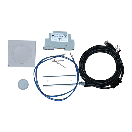
Page 8: Delivery Check
Danfoss Link components in the heating system. ™ An example of a heating system with wireless units is shown in the figure below. The Danfoss Link components are indicated with a dotted line. Danfoss HP kit for DHP-AQ Legend ®... -
Page 9: Safety Instructions
Installation manual Danfoss Link™ HP kit Safety instructions Installation must be carried out in accordance with applicable laws and regulations, as well as these instructions. The cables are live and may cause fatal electrical shock. The heat pump power supply must be switched off before commencing electrical installation. - Page 10 Installation manual Danfoss Link™ HP kit 1. The cover is opened by turning the open/close mechanism, after which the cover can be lifted off. Be careful with the display cable behind the cover. 2. Mount the DIN rail in the prepared holes in the electrical panel. Fasten the rail using screws and a suitable tool.
- Page 11 Installation manual Danfoss Link™ HP kit Wiring 1. Connect the grey wire to the L terminal and the blue wire to the N terminal. 2. Route the cables through the electrical cabinet and connect the grey wire to L 1:1 and the blue wire to N on the connector bank.
- Page 12 Installation manual Danfoss Link™ HP kit 8. Connect the DCM03 cable to the free RJ45 connection on the relay card. Pass the cable up through the cable lead-in and through the membrane nipple. Adjust the length and press the membrane nipple back.
-
Page 13: Service Functions
Click here to add the DCM03 module to Note! During installation, the distance between Danfoss Link™ CC and DCM03 must not exceed 1.5 metres. Connecting other units to Danfoss Link™ CC, wireless connection Connect other service and room units, e.g. HC floor heating and living connect radiator thermostats. Start with the service units. - Page 14 Once the installation is complete, a network test must be carried out to ensure that communication between all added units and Danfoss Link CC™ is stable. Note! Do not carry out the network test until Danfoss Link™ CC has been fitting in its final position. Service functions...
-
Page 15: Troubleshooting
3. Check that DCM is set to Danfoss Link integration and not to Danfoss Online. By pressing the DCM button quickly three times, you will switch between showing status for Danfoss Online and Dan- ™ integration. The LEDs on DCM03 (both red and green) flash rapidly 3 times when status foss Link ™... - Page 16 ™ Link CC manages most functions in the heat pump. In this case, the functions controlled by Danfoss Link CC locked in relation to Online. The table below shows the relationship between disabled and enabled functions from an Online perspective.
-
Page 17: Recycling Instructions
Installation manual Danfoss Link™ HP kit Recycling instructions When the crossed-out wastepaper basket symbol is shown on the product, it means that the product is subject to European Parliament and Council Directive 2002/96/EC. Locate your nearest recycling centre for electrical and electronic products. Adhere to local regulations and do not put old products (e.g. batteries) in your general household waste. - Page 18 VIIFR102 © Danfoss 08/2013...
- Page 19 VIIFR102 © Danfoss 08/2013...
- Page 20 The same applies to products already on order provided that the previously agreed specifications remain unchanged. All trademarks in this material are the property of the respective company. Danfoss and the Danfoss logotype are trademarks which belong to Danfoss A/S. All rights reserved.