Table of Contents
Advertisement
Available languages
Available languages
I 56- 3947- 202
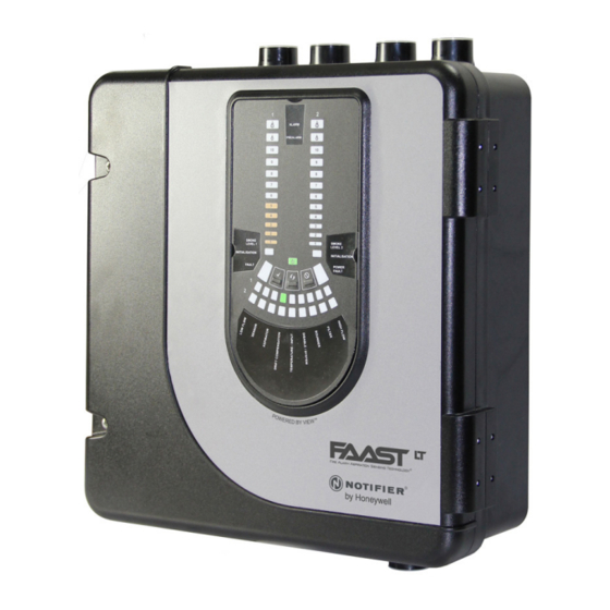
DESCRIPTION
The LT NFXI-ASD Series is part of the Fire Alarm Aspiration
Sensing Technology
(FAAST) family. FAAST is an advanced
®
fire detection system for use where early warning and very early
warning are a requirement. The system continuously draws air
from the controlled environment through a series of sampling holes
to monitor the environment for smoke particulate.
The NFXI-ASD is the addressable version of the FAAST LT range,
communicating with the CIE (Fire Panel) via a proprietary loop
protocol. It is available in 3 different models:
NFXI-ASD11 - Has single channel capability with one laser smoke
sensor.
NFXI-ASD12 - Has single channel capability with two laser smoke
sensors in a common chamber for coincidence
detection.
NFXI-ASD22 - Has two channel capability with two laser smoke
sensors in separate chambers. (one sensor for
each channel).
This guide provides information for mounting and basic installation
using the unit's default factory settings. For more advanced information
please see the FAAST LT Advanced Setup and Control Guide.
SPECIFICATIONS
Electrical Characteristics
Voltage Range:
Supply Current:
1 Channel:
2 Channel:
Communication Loop Supply Voltage: 15 – 29 VDC (Loop current ≤
Communication Loop Standby Current: @ 24V: 900 µA max. (poll once
Module Isolator Characteristics
Maximum rated switching current
(under short circuit, Is max):
Maximum leakage current (IL max)
with the switch open (isolated state):
Maximum series impedance with
the switch closed (Zc max):
N200-102-00
FIRE ALARM ASPIRATION SENSING TECHNOLOGY
QUICK INSTALLATION GUIDE ADDRESSABLE FAAST LT
MODELS NFXI-ASD11, NFXI-ASD12, NFXI-ASD22
18.5 - 31.5 VDC
170mA (typical); 360mA (max) @
24 VDC 25
C (excluding sounders)
o
270mA (typical); 570mA (max) @
24 VDC 25
C (excluding sounders)
o
900mA)
every 5s)
0.9A @ ≤ 29V
15mA
190 m ohm at 15Vdc; 1A
50 mm
60 mm
110 mm
356 mm
Figure 1: Dimensions and Knock-Outs
Power Reset:
Configurable Input: Activation Time:
Relay Contact Ratings:
Environmental Ratings
Temperature:
Relative Humidity:
IP Rating:
Mechanical
Exterior Dimensions:
Wiring:
Maximum Single Pipe Length:
Maximum Branched Pipe Length:
Maximum Number of Holes
Pipe Spec (EN54-20 Compliance):
Outside Pipe Diameter:
Shipping Weight:
PARTS LIST
Description
FAAST LT unit
Mounting bracket
3-pin Terminal block
4-pin Terminal block
2-pin Terminal block
47 k-ohm EOL Resistor
USB Cable
Front Panel Labelling Pack
Wiring Diagram Label
Installation Kit CD
Quick Installation Guide
Aspirating Smoke Detectors supplied and installed within the
EU must conform to the EU Construction Products Regulation
(CPR) 305/2011 and the related European Product Standard EN
54-20. FAAST LT has been tested and certified to ensure that it
conforms to the necessary Standards, but strict adherence to this
instruction guide is advised to ensure that the installation meets
the requirements of the CPR.
1
E N G L I S H
®
50 mm
0.5s
2s (min)
2.0 A @ 30 VDC, 0.5A @ 30 VAC
-10°C to 55°C
10% to 93% (non-condensing)
65
See Figure 1
0.5 mm² to 2 mm² max
100m (Classes B & C) 80m (A)
160m (2 x 80m, Class C)
See Table 1A
to EN 61386
(Crush 1, Impact 1, Temp 31)
25mm (nom) or 27mm (nom)
6.5kg (inc sensors)
Quantity
1
1
6
1
3
2
1
1
1
1
1
Important Note
44 mm
56 mm
135 mm
I56-3947-202
Advertisement
Table of Contents

Related Manuals for Honeywell NOTIFIER NFXI-ASD11


Summary of Contents for Honeywell NOTIFIER NFXI-ASD11
- Page 1 E N G L I S H FIRE ALARM ASPIRATION SENSING TECHNOLOGY ® QUICK INSTALLATION GUIDE ADDRESSABLE FAAST LT I 56- 3947- 202 MODELS NFXI-ASD11, NFXI-ASD12, NFXI-ASD22 50 mm 50 mm 60 mm 44 mm 56 mm DESCRIPTION 110 mm 135 mm The LT NFXI-ASD Series is part of the Fire Alarm Aspiration 356 mm...
-
Page 2: Physical Installation
Warning The performance of this system is dependent upon the pipe network. Any extension or modification to the designed installation may cause improper operation. The operational effects of such changes need to be verified using the PipeIQ 2 design software. Figure 4: How to Knock Out Cable Gland Holes This equipment and all associated pipe work must be installed in... - Page 3 Figure 7: Sequence (1 to 9) to Mount the Detector on the Bracket Pipe Hole Configuration Figure 8 below shows the pipe holes available on the unit. Each unit has 2 pipe holes per channel connected together like a T-Piece. 99 mm If using a 1 channel unit, holes 3 and 4 do not function.
-
Page 4: Wiring Installation
Exhaust Pipe Whenever the FAAST LT is installed outside the risk area, return of the exhaust air back into the protected area can reduce flow faults due to pressure difference. SAMPLING AREA SAMPLING AREA WIRING INSTALLATION Power, Alarm and Control Connections CHANNEL 1 FILTER CHANNEL 2 FILTER EARTH BAR... - Page 5 Fitting the Terminal Blocks WARNING: Switching Inductive Loads To insert the terminal blocks into the unit use the following method: FAAST LT 1 Insert a corner of the block into the slot (see a). 2 Push the length of the block into the slot until the block ‘clicks’ into place, the 2 upper hooks on the block should be visible (see c).
-
Page 6: Setting The Addresses
SETTING THE ADDRESSES POWERING UP Using Default Settings Each aspiration channel uses loop communications to report its status information to the CIE (Fire Panel). As a factory default, 1. Connect a suitable 24VDC supply (complying with European the unit will report smoke alarm and sensor information at an Standard EN 54-4) to pins 1 and 2 on terminal block T1 (See associated sensor address and general alerts and faults on a Table 2) -
Page 7: Front Panel
FRONT PANEL The front panel will be different depending on which of the 3 NFXI- ASD models is being installed, and each is shown below. ALARM The following information is displayed: PREALARM • Detector Status: Normal, Alarm, Fault or Isolate Alarm Level;... - Page 8 Table 4: Front Panel Indicators and Fault Descriptions INDICATOR ACTION WARNING OR TROUBLE COMMENT / ACTION CHANNEL 1/2 ALARM ON Red Channel is in alarm (relay is Default setting (Set by panel) set ON with no delay) 1 BLINK Green When sensor is polled Not when in alarm (Polled by panel)
- Page 9 PREALARM SMOKE Table 5: Front Panel Buttons LEVEL 2 INITIALIZATION BUTTON NORMAL Mode MAINTENANCE Mode RESET When pressed for 2 s, starts PASSWORD When pressed for 2 s latched alarms, faults and POWER PROCEDURE to enter Maintenance sounders (relays) are reset. Alarm controlled by panel. If FAULT mode.
-
Page 10: Laser Safety Information
Using compressed air to clean the pipe system High pressure air flushed through the system could damage the fan, ensure that the FAAST LT unit is sealed or detached Notifier by Honeywell from the system before commencing this procedure. Brooks Road... -
Page 11: Elenco Delle Parti
I T A L I A N O FIRE ALARM ASPIRATION SENSING TECHNOLOGY ® GUIDA DI INSTALLAZIONE RAPIDA FAAST LT INDIRIZZABILE MODELLI NFXI-ASD11, NFXI-ASD12 E NFXI-ASD22 50 mm 50 mm 60 mm 44 mm 56 mm DESCRIZIONE 110 mm La serie LT NFXI-ASD fa parte della famiglia FAAST (Fire Alarm 135 mm 356 mm Aspiration Sensing Technology... - Page 12 Questa apparecchiatura e tutte le tubazioni associate devono essere installate in conformità a tutti i codici e alle normative pertinenti. INSTALLAZIONE FISICA Etichette per pannello anteriore Figura 4: come praticare i fori serracavo Il modello LT NFXI-ASD viene spedito senza etichette applicate sul pannello anteriore.
- Page 13 Figura 7: sequenza (da 1 a 9) per il montaggio del rivelatore Configurazione dei fori di entrata e uscita dei tubi alla staffa Figura 8 di seguito sono mostrati i fori di entrata e uscita dei tubi disponibili sull'unità. Ogni unità dispone di 2 fori per tubi per canale collegati insieme a T.
- Page 14 Tubo di scarico Ogni volta che FAAST LT viene installato al di fuori della zona a rischio, il ritorno dell'aria di scarico nella zona protetta può ridurre i guasti di flusso dovuti alla differenza di pressione. AREA DI CAMPIONAMENTO AREA DI CAMPIONAMENTO INSTALLAZIONE DEL CABLAGGIO Collegamenti di alimentazione, allarme e controllo FILTRO CANALE 1...
- Page 15 Fissaggio morsettiere AVVERTENZA: Commutazione carichi induttivi Per inserire le morsettiere nell’unità utilizzare il seguente metodo: FAAST LT Inserire un angolo della morsettiera nella fessura (vedere a). Premere tutta la lunghezza della morsettiera nella fessura finché non scatta in posizione, i due ganci superiori sulla morsettiera devono essere visibili (vedere c).
- Page 16 IMPOSTAZIONE DEGLI INDIRIZZI ACCENSIONE Utilizzo delle impostazioni predefinite Ogni canale di aspirazione utilizza comunicazioni sul loop per segnalare informazioni sullo stato al CIE (pannello antincendio). Per 1. Collegare un'alimentazione a 24 VCC idonea (in conformità dello impostazione predefinita in fabbrica l'unità segnala informazioni sui standard europeo EN 54-4) ai terminali 1 e 2 sulla morsettiera T1 sensori e sugli allarmi all'indirizzo del sensore associato e avvisi e (vedere Tabella 2)
- Page 17 PANNELLO ANTERIORE Il pannello anteriore differisce a seconda di quale dei 3 modelli NFXI- ASD viene installato, come mostrato di seguito. ALARM Vengono visualizzate le seguenti informazioni: PREALARM • Stato del rivelatore: Normale, Allarme, Guasto • Livello di allarme: Allarme, Preallarme - disponibile solo con pannelli che utilizzano il Protocollo avanzato •...
- Page 18 Tabella 4: indicatori del pannello anteriore e descrizioni dei guasti INDICATORE AZIONE AVVERTENZA O PROBLEMA COMMENTO/AZIONE ALLARME CANALE 1/2 ACCESO rosso Il canale è in allarme (relè Impostazione predefinita (Impostato da pannello) impostato su ON senza ritardo) 1 verde LAMPEGGIO verde Quando il sensore è...
- Page 19 PREALARM SMOKE Tabella 5: pulsanti del pannello anteriore LEVEL 2 PULSANTE INITIALIZATION Modalità NORMALE Modalità di MANUTENZIONE RESET Quando premuto per Premendo per 2 secondi vengono resettati allarmi con memoria, guasti e POWER 2 secondi, avvia la sirene (relè). Allarme controllato dal pannello. Se l'allarme persiste, FAULT PROCEDURA DI reimpostare immediatamente dopo il ripristino.
-
Page 20: Connessione Usb
Utilizzo di aria compressa per pulire il sistema di tubature L’aria ad alta pressione convogliata nel sistema potrebbe danneggiare la ventola; assicurarsi che l’unità FAAST LT sia sigillata o scollegata dal sistema prima di avviare la procedura. by Honeywell Notifier CONNESSIONE USB Notifier Italia SRL, Via Grandi 22, La connessione con PC è... -
Page 21: Especificaciones
E S P A Ñ O L TECNOLOGÍA FIRE ALARM ASPIRATION SENSING TECHNOLOGY ® GUÍA DE INSTALACIÓN RÁPIDA DE FAAST LT DIRECCIONABLE MODELOS NFXI-ASD11, NFXI-ASD12 Y NFXI-ASD22 50 mm 50 mm 60 mm 44 mm DESCRIPCIÓN 56 mm 110 mm La serie LT NFXI-ASD forma parte de la familia Fire Alarm Aspiration 135 mm Sensing Technology... -
Page 22: Instalación Física
Este equipo, junto con la canalización asociada, debe instalarse de conformidad con los códigos y reglamentaciones pertinentes. INSTALACIÓN FÍSICA Etiquetas del panel frontal LT NFXI-ASD no se entrega con las etiquetas del panel frontal ya colocadas. De este modo, el instalador puede elegir el idioma correspondiente para la Figura 4: Cómo realizar los orificios de instalación del pack de etiquetas del panel frontal. - Page 23 Figura 7: Secuencia (1-9) para montar el detector en el soporte Configuración de orificios de tuberías La Figura 8 muestra los orificios de tuberías disponibles en la unidad. Cada unidad cuenta con 2 orificios de tuberías por canal conectados entre sí...
-
Page 24: Instalación Del Cableado
Tubería de escape Cuando el FAAST LT se instala fuera de la zona de riesgo, el retorno del aire de escape a la zona protegida puede reducir los errores de flujo debidos a la diferencia de presión. ÁREA DE MUESTREO ÁREA DE MUESTREO INSTALACIÓN DEL CABLEADO Conexiones de alimentación, alarma y control... - Page 25 Instalación de los bloques de terminales ADVERTENCIA: Conmutación de cargas inductivas Utilice este método para insertar los bloques de terminales en la unidad: FAAST LT Inserte una esquina del bloque en la ranura (ver a). Apriete el bloque a lo largo en la ranura hasta que el bloque haga un sonido al quedar colocado;...
- Page 26 ESTABLECIMIENTO DE LAS DIRECCIONES ENCENDIDO Uso de ajustes predeterminados Cada canal de aspiración usa el lazo de comunicaciones para transmitir su información de estado a la central de incendios. De manera 1. Conecte una fuente de alimentación de 24 V de CC adecuada (que predeterminada,la unidad transmite la información del sensor y la alarma cumpla con la norma europea EN 54-4) a los terminales 1 y 2 del bloque de humo a una dirección del sensor asociada y las averías y alertas...
-
Page 27: Panel Frontal
PANEL FRONTAL El panel frontal es distinto en cada uno de los tres modelos de NFXI-ASD; se muestran los tres a continuación. ALARMA Se muestra la siguiente información: PREALARMA • Estado del detector: Normal, Alarma, Avería o Aislamiento Nivel de alarma: alarma, prealarma (solo disponible en paneles que •... - Page 28 Tabla 4: Indicadores del panel frontal y descripciones de las averías INDICADOR ACCIÓN ADVERTENCIA O PROBLEMA COMENTARIO / ACCIÓN ALARMA CANAL 1/2 ENCENDIDO rojo El canal está en alarma (relé Configuración por defecto (establecido por panel) establecido en ENCENDIDO sin retardo) 1 PARPADEO verde Cuando se interroga el sensor...
- Page 29 PREALARM SMOKE Tabla 5: Botones del panel frontal LEVEL 2 INITIALIZATION BOTÓN Modo NORMAL Modo MANTENIMIENTO REARME Al pulsarlo durante 2 s, se inicia el Al pulsarlo durante 2 s, las alarmas enclavadas, las averías y las POWER PROCEDIMIENTO DE CONTRASEÑA sirenas (relés) se rearman.
- Page 30 Configuración de otras opciones Para cambiar las opciones predeterminadas, será necesario conectar el detector a un equipo de sobremesa o portátil que tenga el software PipeIQ 2 instalado. Consulte la Guía de control y configuración avanzada de FAAST LT para obtener más información. Nota: El cable de conexión USB debe retirarse durante el funcionamiento normal.
-
Page 31: Spezifikation
D E U T S C H FIRE ALARM ASPIRATION SENSING TECHNOLOGY ® KURZANLEITUNG ZUR INSTALLATION FÜR DIE ADRESSIERBAREN FAAST-LT- MODELLE NFXI-ASD11, NFXI-ASD12 UND NFXI-ASD22 50 mm 50 mm 60 mm 44 mm BESCHREIBUNG 56 mm Die LT NFXI-ASD-Serie ist Teil der FAAST-Produktfamilie (Fire Alarm 110 mm Aspiration Sensing Technology ). - Page 32 Das Gerät und alle zugehörigen Rohre müssen entsprechend allen geltenden Bestimmungen und Vorschriften installiert werden. INSTALLATION Beschriftungsschilder für Bedienfeld Abbildung 4: Herausbrechen der Der LT NFXI-ASD wird ohne Beschriftung des Bedienfelds geliefert. Kabelöffnungen Dadurch kann der Monteur die für die Installation benötigte Sprache aus dem Beschriftungsset für das Bedienfeld auswählen.
- Page 33 Abbildung 7: Reihenfolge (1 bis 9) zur Montage des Melders an Rohrkonfiguration der Halterung Abbildung 8 zeigt die auf dem Gerät vorhandenen Rohröffnungen. Jeder Kanal der Einheit weist zwei Rohröffnungen auf, die T-förmig miteinander verbunden sind. Bei Verwendung einer Einheit mit einem 99 mm Kanal besitzen die Löcher 3 und 4 keine Funktion.
- Page 34 Auslassrohr Wird das FAAST LT-Gerät außerhalb des Risikobereichs installiert, so können durch den Rückfluss der Abluft zurück in den geschützten Bereich Luftstromstörungen aufgrund Druckunterschieden verringert werden. PROBENAHMEBEREICH PROBENAHMEBEREICH VERDRAHTUNG Anschlüsse für Spannungsversorgung, Alarm und Steuerung FILTER KANAL 1 FILTER KANAL 2 MONTAGE ERDUNGS- SCHIENE...
- Page 35 Montage der Anschlussklemmen WARNUNG: Schalten von induktiver Lasten Um die Anschlussklemmen einzusetzen, verfahren Sie wie folgt: FAAST LT Setzen Sie eine Ecke der Anschlussklemme in den Steckplatz ein (siehe a). Schieben Sie die Anschlussklemme in den Steckplatz, bis die Klemme ‚einrastet‘; die zwei oberen Haken auf die Klemme müssen sichtbar sein (siehe c).
- Page 36 ADRESSEN EINSTELLEN EINSCHALTEN Werkseinstellungen verwenden Jeder Ansaugkanal übermittelt ihre Statusinformationen über eine Ringkommunikation an die BMZ (Brandmelderzentrale). In der 1. Schließen Sie an Klemme 1 und Klemme 2 auf der Klemmleiste Werkseinstellung übermittelt das Gerät bei einer entsprechenden T1 (siehe Tabelle 2) eine geeignete 24-V-DC-Spannungsversorgung Sensoradresse Rauchalarm- und Sensorinformationen und bei einer (gemäß...
- Page 37 BEDIENFELD Je nachdem, welches der drei NFXI-ASD-Modelle installiert wird, sieht das Bedienfeld unterschiedlich aus. Alle Ausführungen sind unten ALARM dargestellt. VORALARM Die folgenden Informationen werden angezeigt: • Melderstatus: Normal, Alarm, Störung oder Abschaltung • Alarmstufe; Alarm, Voralarm – nur bei Bedienfeldern mit erweitertem Protokoll verfügbar •...
- Page 38 Tabelle 4: Anzeigen auf dem Bedienfeld und Fehlerbeschreibungen Anzeige Aktion Warnung oder problem Kommentar / aktion Alarm kanal 1/2 Ein rot Kanal befindet sich im alarmzustand Standardeinstellung (von bedienfeld (relais wird ohne verzögerung festgelegt) eingeschaltet) 1 x grün blinkend Bei abfrage des melders Nicht im alarmzustand (poll durch bedienfeld)
- Page 39 PREALARM SMOKE Tabelle 5: Tasten auf dem Bedienfeld LEVEL 2 TASTE NORMALER Modus WARTUNGS-Modus INITIALIZATION ZURÜCKSETZEN Durch Drücken und Halten für Durch Drücken und Halten für 2 Sekunden werden die gespeicherten POWER 2 Sekunden wird die Alarm-, Störungs- und Alarmgeber-Meldungen (Relais) zurückgesetzt. FAULT PASSWORTSEQUENZ zum Der Alarm wird von der Anlage gesteuert.
-
Page 40: Usb-Anschluss
Lüfter beschädigen. Bitte stellen Sie vor dem Ausblasen des Rohrnetzes sicher, das beim Ausblasprozess des FAAST LT, keine hochkomprimierte Luft ins Gerät gelangt. Schließen Sie Notifier by Honeywell daher mittels Kugelhahn die Flussrichtung zum FAAST LT. Notifier Sicherheitssysteme GmbH, Stadionring 32,... -
Page 41: Caractéristiques Techniques
F R A N Ç A I S FIRE ALARM ASPIRATION SENSING TECHNOLOGY ® GUIDE D'INSTALLATION RAPIDE DU SYSTÈME FAAST LT ADRESSABLE MODÈLES NFXI-ASD11, NFXI-ASD12 ET NFXI-ASD22 50 mm 50 mm 60 mm 44 mm 56 mm DESCRIPTION 110 mm La série LT NFXI-ASD fait partie de la gamme FAAST (Fire Alarm Aspiration 135 mm 356 mm... -
Page 42: Installation Physique
INSTALLATION PHYSIQUE Étiquettes du panneau avant Le LT NFXI-ASD est expédié sans avoir apposé les étiquettes du panneau avant. Cela permet à l'installateur de choisir la langue requise pour l'installation dans l'assortiment d'étiquetage du panneau avant. Figure 4 : C omment perforer La figure 2 montre où les étiquettes doivent être placées : les ... - Page 43 Figure 7 : É tapes de montage (1 à 9) du détecteur sur la plaque de Configuration des orifices pour les tuyaux fixation La figure 8 ci-dessous montre les orifices pour tube disponibles sur l'appareil. Chaque appareil dispose de 2 orifices pour tube connectés entre eux comme un branchement en T.
- Page 44 Tuyau d'échappement Lorsque l'appareil FAAST LT est installé en dehors de la zone à risque, le retour de l'air évacué dans la zone protégée peut réduire les défauts de flux dus à une différence de pression. ZONE D'ÉCHANTILLONNAGE ZONE D'ÉCHANTILLONNAGE RÉALISATION DU CÂBLAGE Connexions d'alimentation, d'alarme et de commande FILTRE DU CANAL 1...
- Page 45 Montage des bornes AVERTISSEMENT : Commutation de charges inductives Pour insérer les blocs de bornes dans l’unité, procéder comme suit : FAAST LT Insérer l’angle du bloc dans la fente (voir a). Pousser le bloc dans la fente en appuyant sur la longueur, jusqu’à ce que le bloc se mette en place avec un déclic, les 2 crochets supérieurs du bloc doivent être visibles (voir c).
-
Page 46: Mise Sous Tension
RÉGLAGE DES ADRESSES MISE SOUS TENSION En utilisant les réglages par défaut Chaque canal d'aspiration utilise des communications en boucle pour 1. Connectez une source d'alimentation 24 VDC appropriée (conforme à la transmettre ses informations d'état au CIE (panneau d'incendie). Par défaut norme européenne EN 54-4) aux connexions 1 et 2 du bornier T1 (voir (réglages d'usine), l'appareil enverra les alarmes de détection de fumée le tableau 2). -
Page 47: Panneau Avant
PANNEAU AVANT Le panneau avant sera différent en fonction du modèle NFXI-ASD installé. Les 3 modèles disponibles sont illustrés ci-dessous. ALARME Les informations suivantes sont affichées : PRÉ ALARME • État du détecteur : Normal, Alarme, Défaut ou Isolement. • Niveau d'alarme : Alarme, Préalarme (disponible seulement sur les ... - Page 48 Tableau 4 : I ndicateurs du panneau avant et description des anomalies INDICATEUR ACTION AVERTISSEMENT OU PROBLÈME COMMENTAIRE / ACTION ALARME DE ALLUMÉ en rouge Le canal est en état d'alarme (le relais est Réglage par défaut CANAL 1/2 (réglé par le panneau) réglé sur MARCHE sans temporisation). 1 CLIGNOTEMENT en vert Quand le détecteur est interrogé.
- Page 49 PREALARM SMOKE Tableau 5 : Touches du panneau avant LEVEL 2 TOUCHE INITIALIZATION Mode NORMAL Mode MAINTENANCE RÉARMEMENT Maintenir cette touche enfoncée Lorsque cette touche est maintenue enfoncée pendant 2 secondes, les POWER pendant 2 secondes pour lancer anomalies et les résonateurs (relais) verrouillés sont réinitialisés. Alarme FAULT la SAISIE DU MOT DE PASSE contrôlée par l'équipement de contrôle et de signalisation.
-
Page 50: Connexion Usb
De l’air sous pression envoyé dans le système peut endommager le Notifier by Honeywell ventilateur ; veiller à la ce que l’unité FAAST LT soit hermétiquement Honeywell Life Safety SA fermée ou séparée du système avant de commencer cette intervention. LIEGE AIRPORT...