Star Micronics SP500 Series User Manual
Dot matrix printer
Hide thumbs
Also See for SP500 Series:
- User manual (128 pages) ,
- Technical manual (73 pages) ,
- Application manual (15 pages)

Related Manuals for Star Micronics SP500 Series


Summary of Contents for Star Micronics SP500 Series
- Page 1 DOT MATRIX PRINTER SP500 SERIES USER’S MANUAL MODE D’EMPLOI BEDIENUNGSANLEITUNG MANUALE DI ISTRUZIONI...
- Page 2 European Communities as of July 1993. The above statement applies only to printers marketed in EU. Trademark acknowledgments SP500 Series: Star Micronics Co., Ltd. ESC/POS: Seiko Epson Corporation Notice • All rights reserved. Reproduction of any part of this manual in any form whatsoever, without STAR’s express permission is forbidden.
-
Page 3: Table Of Contents
TABLE OF CONTENTS 1. Outline ... 1 2. Unpacking and Installation ... 2 2-1. Unpacking ... 2 2-2. Locating the Printer ...3 2-3. Handling Care ... 3 2-4. Maintenance ...3 3. Parts Identification and Nomenclature ... 4 4. Connecting Cables and Power Cord ... 6 4-1. -
Page 4: Outline
The SP500 Series Serial Impact Dot Matrix Printer is designed for use with electronic instruments such as POS, banking equipment, computer peripheral equipment, etc. The major features of the SP500 series are as follows: 1. Bi-directional printing at approx. 4 lines/sec. -
Page 5: Unpacking And Installation
2. Unpacking and Installation 2-1. Unpacking After unpacking the unit, check that all the necessary accessories are included in the package. Tear bar model Printer Ribbon cartridge If anything is missing, contact the dealer where you bought the printer and ask them to supply the missing part. -
Page 6: Locating The Printer
2-2. Locating the Printer When you locate your printer, keep the following tips in mind: 1. Protect your printer from excessive heat such as direct sunlight or heaters, and keep it away from moisture and dust. 2. Place the printer on a firm, level surface which is fairly vibration-free. 3. -
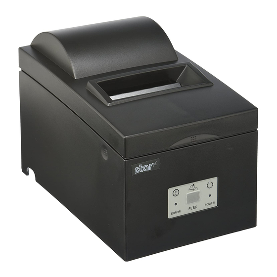
Page 7: Parts Identification And Nomenclature
3. Parts Identification and Nomenclature Tear bar model Cover Protects the printer from dust and reduces noise. Do not open the cover while printing. Control panel Features one control switch and two indicators to indicate printer status. Interface connector Power connector Connects the printer with For connection of host computer. - Page 8 Auto cutter model Cover Protects the printer from dust and reduces noise. Do not open the cover while printing. Control panel Features one control switch and two indicators to indicate printer status. Power connector Interface connector For connection of Connects the printer with the power cord.
-
Page 9: Connecting Cables And Power Cord
4. Connecting Cables and Power Cord 4-1. Connecting the Interface Cable Note: Before connecting/disconnecting the interface cable, make sure that power to the printer and all the devices connected to the printer is turned off. Also make sure the power cable plug is disconnected from the AC outlet. -
Page 10: Connecting To A Peripheral Unit
4-2. Connecting to a Peripheral Unit You can connect a peripheral unit to the printer using a modular plug. The following describes how to install the ferrite core and make the actual connection. See “Modular plug” on page 115 for details about the type of modular plug that is required. -
Page 11: Connecting The Power Cord
4-3. Connecting the Power Cord Note: Before connecting/disconnecting the power cord, make sure that power to the printer and all the devices connected to the printer is turned off. Also make sure the power cable plug is disconnected from the AC outlet. (1) Check the label on the back or bottom of the printer to make sure its voltage matches that of the AC outlet. -
Page 12: Turning Power On
4-4. Turning Power On Make sure that the power cord has been connected as described in 4-3. (1) Set the power switch located on the right side of the printer to on. The POWER lamp on the control panel will light up. Important! We recommend that you unplug the printer from the power outlet whenever you do not plan to use it for long periods. -
Page 13: Installing The Cable
4-6. Installing the cable Install the cable as shown in the diagram below. – 10 –... -
Page 14: Switch Blind Installation
4-7. Switch Blind Installation It is not necessary to install the switch blind. Only install it if it is necessary for you. By installing the switch blind, the following become possible. • Preventing the power switch from being operated by mistake. •... -
Page 15: Loading The Ribbon Cartridge And Paper
5. Loading the Ribbon Cartridge and Paper 5-1. Tear Bar Model 5-1-1. Loading the Ribbon Cartridge Cover Power off Fig. 5-1 Opening the cover Ribbon separator Print head Ink ribbon Ribbon feed knob Notched part Fig. 5-2 Loading the ribbon cartridge 1 Turn off power to the printer. - Page 16 Fig. 5-3 Removing the ribbon cartridge 5-1-2. Loading the paper Fig. 5-4 Removing the cover Note: When removing the ribbon cartridge, raise the A section and then remove it by hold- ing the B section as shown in Fig. 5-3. 1 Open the cover.
- Page 17 Roll paper Fig. 5-5 Setting the paper Roll paper Paper feeder Paper exit Fig. 5-6 Loading the paper 4 While observing the direction of the roll, set the paper roll into the hol- low as shown in Fig. 5-5. 5 Insert the edge of the paper into the paper feeder (black plastic part).
-
Page 18: Auto Cutter Model
5-2. Auto Cutter Model 5-2-1. Loading the Ribbon Cartridge Cover Power off Fig. 5-8 Opening the cover Auto cutter Fig. 5-9 Raise the auto cutter 1 Turn off power to the printer. 2 Open the cover. Important! 1. Do not touch the print head imme- diately after printing as it can be extremely hot. - Page 19 Ribbon separater Print head Ink ribbon Ribbon feed knob Notched part Fig. 5-10 Loading the ribbon cartridge Fig. 5-11 Removing the ribbon cartridge 4 Place the ribbon cartridge in the direction shown in Fig. 5-10 and Auto cutter press it down to load it. If loading of the ribbon cartridge is not satisfac- tory, press down the cartridge while rotating the ribbon feed knob in the...
- Page 20 5-2-2. Loading the Paper Fig. 5-12 Removing the cover Roll paper Fig. 5-13 Setting the paper 1 Open the cover. Cover Important! 1. Do not touch the print head imme- diately after printing as it can be extremely hot. 2. Do not touch the cutter blade. ·...
-
Page 21: Installing The Roll Paper Guide
Roll paper Paper feeder Fig. 5-14 Loading the paper 5-3. Installing the Roll Paper Guide Roll paper guide Fig. 5-15 Installing the roll paper guide 5 Inset the edge of the paper into the paper feeder (black plastic part). If inserted correctly, the edge of the paper will pass through the auto cutter paper slit. -
Page 22: Control Panel And Other Functions
6. Control Panel and Other Functions 6-1. Control Panel 2 FEED button 3 ERROR lamp (Red LED) 6-2. Basic Indicators POWER lamp Power On/Off On/Off Online Offline 1 POWER lamp (Green LED) Lights when the power is ON 2 FEED button Press the FEED button to feed roll paper. -
Page 23: Errors
6-3. Errors 1) Recoverable error Error Description POWER lamp Paper end error Waiting for recovery to online Flashes (Off: 0.25 status after paper setting sec./Off: 0.25 sec.) Paper near end er- Head high tem- Flashes (Off: 1 perature detection sec./Off: 1 sec.) Board high tem- Flashes (On: 2 sec./ perature detection... - Page 24 Note 1) If the cutter doesn’t return to the home position, or doesn’t perform the initial movement, it cannot be recovered. 2) If the paper is jammed, turn the power OFF, clear the jammed paper, then turn the power ON. 3) When the error occurs: STAR Mode: Non recoverable error ESC/POS Mode: Recoverable error...
-
Page 25: Adjustment Mode
6-4. Adjustment Mode There are the following four adjustment modes. The device will enter the adjustment mode if your turn it on while pressing the FEED switch. The Self Printing Mode is entered by releasing the FEED switch after the buzzer sounds once. - Page 26 6-4-1. Self Printing Mode Self-printing will be performed according to the VER. NO., Memory switch settings, DIP switch settings and character order. When the FEED switch is held continuously or when the FEED switch is depressed at the time of the end of self- printing, only the characters will be printed out repeatedly.
- Page 27 6-4-2. Hexadecimal Dump Mode Each of the signals sent from the computer to the printer will be printed out in hexadecimal code. This function allows you to check if a control code sent to the printer by the program being used is correct or not. The last line is not printed if its data is less than one full line.
- Page 28 – 25 –...
- Page 29 TABLE DES MATIERES 1. Introduction ... 27 2. Déballage et inspection ...28 2-1. Déballage ... 28 2-2. Emplacement de l’imprimante ...29 2-3. Précautions de manipulation ... 29 2-4. Entretien ... 29 3. Identification des pièces et nomenclature ... 30 4. Câbles de connexion et câble d’alimentation ... 32 4-1.
-
Page 30: Introduction
électroniques tels que des terminaux points de vente, du matériel bancaire, du matériel périphérique pour ordinateurs, etc. Les caractéristiques principales des modèles de la série SP500 sont les suivantes: 1. Impression bi-directionnelle à 4 lignes/sec. environ. 2. Interface série ou parallèle. -
Page 31: Déballage Et Inspection
2. Déballage et inspection 2-1. Déballage Après avoir déballé l’appareil, vérifiez si tous les accessoires nécessaires se trouvent dans la boîte. Modèle avec barre de tension Imprimante Cartouche à ruban Si l’un des éléments mentionnés ci-dessus ne se trouve pas dans la caisse, adressez-vous au magasin où... -
Page 32: Emplacement De L'imprimante
2-2. Emplacement de l’imprimante Pour installer correctement l’imprimante, gardez à l’esprit les conseils suivants: 1. Mettez l’imprimante à l’abri de températures excessivement élevées comme en plein soleil ou à proximité d’un appareil de chauffage, et à l’abri de l’humidité et de la poussière. -
Page 33: Identification Des Pièces Et Nomenclature
3. Identification des pièces et nomenclature Modèle avec barre de tension Capot Protège l’imprimante de la poussière et réduit le bruit. Ne pas ouvrir le capot pendant l’impression. Panneau de commande Comprend un commutateur de commande et trois témoins indiquant le statut de l’imprimante. - Page 34 Modèle avec coupe-papier automatique Capot Protège l’imprimante de la poussière et réduit le bruit. Ne pas ouvrir le capot pendant l’impression. Panneau de commande Comprend un commutateur de commande et trois témoins indiquant le statut de l’imprimante. Connecteur Connecteur d’interface d’alimentation Ce connecteur vous permet de Pour la connexion...
-
Page 35: Câbles De Connexion Et Câble D'alimentation
4. Câbles de connexion et câble d’alimentation 4-1. Connexion du câble d’interface Remarque:Avant de connecter ou déconnecter le câble d’interface, veillez à ce que l’imprimante et tous les appareils qui y sont connectés soient hors tension. Veillez également à débrancher le câble d’alimentation de la prise secteur. -
Page 36: Raccordement D'un Appareil Périphérique
4-2. Raccordement d’un appareil périphérique Vous pouvez raccorder un appareil périphérique à l’imprimante à l’aide d’une fiche modulaire. Nous expliquons ci-dessous comment installer le tore de ferrite et faire le raccordement proprement dit. Pour les détails sur le type de fiche modulaire à... -
Page 37: Connexion De Câble D'alimentation Secteur Optionnel
4-3. Connexion de câble d’alimentation secteur optionnel Remarque:Avant de connecter ou déconnecter câble d’alimentation, veillez à ce que l’imprimante et tous les appareils qui y sont connectés soient hors tension. Veillez également à débrancher le câble d’alimentation de la prise secteur. (1) Vérifiez, sur l’étiquette apposée à... -
Page 38: Mise Sous Tension De L'imprimante
4-4. Mise sous tension de l’imprimante Assurez-vous d’avoir bien connecté le câble d’alimentation comme décrit à la section 4-3. (1) Placez l’interrupteur d’alimentation, situé sur le côté droit de l’imprimante, sur la position sous tension. La DEL POWER s’allume au panneau des commandes. Attention! Nous vous recommandons de débrancher l’imprimarte du secteur lors- que vous ne comptez pas l’utiliser pendant une période prolongée. -
Page 39: Installation Du Câble
4-6. Installation du câble Installez le câble, comme indiqué sur le schéma ci-dessous. – 36 –... -
Page 40: Installation Du Cache De L'interrupteur
4-7. Installation du cache de l’interrupteur L’installation de ce cache n’est pas nécessaire. Ne l’installez que si vous souhaitez : • éviter que l’interrupteur d’alimentation ne soit actionné par erreur ; • vous assurer que personne ne peut l’actionner facilement. Installez le cache, comme indiqué... -
Page 41: Installation D'une Cartouche À Ruban Et Chargement Du Papier
5. Installation d’une cartouche à ruban et chargement du papier 5-1. Modèle avec barre de tension 5-1-1. Installation d’une cartouche à ruban Capot Hors tension Fig. 5-1. Ouvrez le capot Séparateur de ruban Tête d’impression Ruban encreur Bouton d’alimentation du ruban Parties avec encoches Fig. - Page 42 Fig. 5-3 Dégagement de la cartouche du ruban 5-1-2. Chargement du papier Fig. 5-4 Dépose du capot Remarque: Pour enlever la cartouche à ruban, soulevez la partie A, puis enlevez la cartouche en la tenant par la partie B comme indiqué...
- Page 43 Rouleau de papier Fig. 5-5 Chargement du papier Rouleau de papier Fente de sortie de papier Mécanisme d’avance de papier Fig. 5-6 Chargement du papier 4 En faisant attention au sens du rou- leau, mettez le rouleau de papier en place dans le creux, comme indiqué...
-
Page 44: Modèle Avec Coupe-Papier Automatique
5-2. Modèle avec coupe-papier automatique 5-2-1. Installation d’une cartouche à ruban Capot Hors tension Fig. 5-8 Ouvrez le capot Unité de découpage automatique Fig. 5-9 Redressement de l’unité de découpage automatique 1 Mettez l’imprimante hors tension. 2 Ouvrez le capot. Attention! 1. - Page 45 Séparateur de ruban Tête d’impression Ruban encreur Bouton d’alimenta- tion du ruban Parties avec encoches Fig. 5-10 Mise en place de la cartouche à ruban Fig. 5-11 Dégagement de la cartouche du ruban Unité de 4 Mettez la cartouche à ruban en place découpage dans le sens indiqué...
- Page 46 5-2-2. Chargement du papier Fig. 5-12 Dépose du capot Rouleau de papier Fig. 5-13 Chargement du papier 1 Ouvrez le capot. Capot Attention! 1. Ne touchez pas la tête d’impres- sion immédiatement après une impression ; en effet, celle-ci peut être très chaude.
-
Page 47: Installation Du Guide Du Rouleau De Papier
Rouleau de papier Fente de sortie de papier Fig. 5-14 Chargement du papier 5-3. Installation du guide du rouleau de papier Guide du rouleau de papier Fig. 5-15 Installation du guide du rouleau de papier 5 Insérez l’extrémité du papier dans le mécanisme d’avance de papier (partie en plastique noir). -
Page 48: Panneau De Commande Et Autres Fonctions
6. Panneau de commande et autres fonctions 6-1. Panneau de commande 2 Témoin FEED (avance de papier) 3 Témoin ERROR (erreur) 6-2. Indicateurs de base Témoin POWER Sous tension/hors Sous tension/hors tension tension En ligne Sous tension Hors ligne Hors tension 1 Témoin POWER (DEL verte) S’allume quand l’appareil est sous tension. -
Page 49: Erreurs
6-3. Erreurs 1) Erreur récupérable Description de Témoin POWER l’erreur Erreur de fin de Sous tension papier Attente de Clignote (Hors récupération du statut tension : 0,25 s/ en ligne après Hors tension : chargement du papier 0,25 s) Erreur de proximité Sous tension de fin de papier Détection de... - Page 50 Remarque 1) Si le coupe-papier ne revient pas dans sa position d’origine ou n’exécute pas le mouvement initial, la récupération est impossible. 2) Si le papier est coincé, mettez l’appareil hors tension, dégagez le bourrage de papier, puis mettez l’appareil sous tension. 3) En cas d’erreur: Mode STAR : Erreur non récupérable Mode ESC/ POS : Erreur récupérable...
-
Page 51: Mode De Réglage
6-4. Mode de réglage Quatre modes de réglage sont disponibles. L’appareil passe en mode de réglage si vous le mettez sous tension tout en appuyant sur le commutateur FEED. Vous pouvez passer en mode Auto-impression en relâchant le commutateur FEED dès que l’avertisseur sonore retentit une fois. Passez en mode de réglage d’alignement des points en relâchant le commutateur FEED dès que l’avertisseur sonore retentit deux fois. - Page 52 6-4-1. Mode Auto-impression Le test d’impression sera effectué conformément au réglage du numéro de vérification, du commutateur mémoire des commutateurs DIP et de l’ordre des caractères. Si vous maintenez la pression sur la touche FEED ou si vous appuyez sur la touche FEED à la fin du test d’impression, seuls les caractères seront imprimés à...
- Page 53 6-4-2. Vidage hexadécimal Chacun des signaux envoyés de l’ordinateur à l’imprimante sera imprimé en code hexadécimal. Cette fonction vous permet de vérifier si un code de contrôle envoyé à l’impri- mante par le programme utilisé est correct ou non. La dernière ligne n’est pas imprimée si les données correspondantes ne remplissent pas une ligne complète.
- Page 54 – 51 –...
- Page 55 INHALTSVERZEICHNIS 1. Kurzbeschreibung ... 53 2. Auspacken und Aufstellen ...54 2-1. Überprüfen ...54 2-2. Wahl eines Aufstellungsorts für den Drucker ... 55 2-3. Hinweise zum Umgang ...55 2-4. Wartung ... 55 3. Beschreibung und Bezeichnung der Geräteteile ... 56 4. Anschlußkabel und Netzkabel ...58 4-1.
-
Page 56: Kurzbeschreibung
Der serielle Nadeldrucker der Serie SP500 ist zur Verwendung mit elektroni- schen Instrumenten wie POS, Bankgeräte, Computerzubehör, etc. gedacht. Die wichtigsten Merkmale der Serie SP500 sind: 1. Bidirektioneller Druck mit ca. 4 Zeilen/s 2. Serielle oder parallele Schnittstelle 3. Pufferspeicher erlaubt, Druckdaten auch während des Druckvorgangs zu empfangen. -
Page 57: Auspacken Und Aufstellen
2. Auspacken und Aufstellen 2-1. Überprüfen Sie den Kartoninhalt, und vergewissern Sie sich, daß alle unten abgebildeten Teile vorhanden sind. Abreißkantenmodell Drucker Farbbandkassette Bedienungsanleitung Falls Teile fehlen, wenden Sie sich zwecks Nachlieferung bitte an den Fachhan- del, bei dem das Gerät gekauft wurde. Im Hinblick auf einen eventuellen zukünftigen Transport des Druckers empfiehlt es sich, den Lieferkarton und das gesamte Verpackungsmaterial aufzubewahren. -
Page 58: Wahl Eines Aufstellungsorts Für Den Drucker
2-2. Wahl eines Aufstellungsorts für den Drucker Bevor Sie den Drucker auspacken, sollten Sie einige Minuten damit verbringen, einen geeigneten Aufstellungsort auszusuchen. Denken Sie dabei an die folgenden Punkte: 1. Den Drucker vor Hitzequellen wie direktem Sonnenlicht oder Heizkörpern schützen und von Feuchtigkeit und Staub fernhalten. 2. -
Page 59: Beschreibung Und Bezeichnung Der Geräteteile
3. Beschreibung und Bezeichnung der Geräteteile Abreißkantenmodell Abdeckung Schüzt den Drucker vor Staub, und reduziert das Betriebsgeräusch. Nicht die Frontabdeckung während des Druckens öffnen. Bedienfeld Hat einen Steuerschalter und zwei Anzeigen zur Anzeige des Druckerzustands. Netzanschluß Schnittstellenbuchse Zum Anschließen Zum Anschluß des Druckers des Netzkabels. - Page 60 Auto-Schneidwerkmodell Abdeckung Schüzt den Drucker vor Staub, und reduziert das Betriebsgeräusch. Nicht die Frontabdeckung während des Druckens öffnen. Bedienfeld Hat einen Steuerschalter und zwei Anzeigen zur Anzeige des Druckerzustands. Netzanschluß Schnittstellenbuchse Zum Anschließen Zum Anschluß des Druckers des Netzkabels. an den Hostcomputer. Abb.
-
Page 61: Anschlußkabel Und Netzkabel
4. Anschlußkabel und Netzkabel 4-1. Anschließen des Schnittstellenkabels Hinweis: Vor dem Anschließen/Abtrennen des Schnittstellenkabels stellen Sie sicher, daß der Drucker und alle angeschlossenen Gerät ausge- schaltet sind. Außerdem sollte der Netzstecker abgezogen sein. (1) Schließen Sie das Schnittstellenkabel an die Buchse an der Rückseite des Druckers an. -
Page 62: Anschluß An Ein Peripheriegerät
4-2. Anschluß an ein Peripheriegerät Es kann ein Peripheriegerät an den Drucker mit einem Modularstecker ange- schlossen werden. Im folgenden wird beschrieben, wie der Ferritkern angebracht und die Verbindung hergestellt wird. Siehe “Modularstecker” auf Seite 115 für den Typ von Modularstecker, der dazu erforderlich ist. Beachten Sie, daß der Drucker nicht mit einem Modularstecker oder Kabel ausgestattet ist. -
Page 63: Anschließen Des Optionalen Netzkabels
4-3. Anschließen des optionalen Netzkabels Hinweis: Vor dem Anschließen/Abtrennen des Netzkabels stellen Sie sicher, daß der Drucker und alle angeschlossenen Gerät ausgeschaltet sind. Außerdem sollte der Netzstecker abgezogen sein. (1) Durch Überprüfen des Typenschilds auf der Rück- oder Unterseite des Druckers sicherstellen, daß... -
Page 64: Einschalten
4-4. Einschalten Stellen Sie sicher, daß das Netzkabel angeschlossen ist, wie in 3-3 beschrieben. (1) Netzschalter auf der rechten Seite des Geräts auf Ein (ON) stellen. Das POWER-Lämpchen am Bedienfeld leuchtet auf. Wichtig! Wir empfehlen, den Netzstecker aus der Steckdose zu ziehen, wenn der Drucker längere Zeit lang nicht benutzt werden soll. -
Page 65: Installieren Der Kabel
4-6. Installieren der Kabel Installieren Sie die Kabel wie in den nachfolgenden Abbildungen dargestellt. – 62 –... -
Page 66: Einsetzen Der Schalterabdeckung
4-7. Einsetzen der Schalterabdeckung Es ist nicht notwendig, die Schalterabdeckung zu verwenden. Setzen Sie diese nur ein, wenn für Sie erforderlich ist, daß • der Netzschalter nicht versehentlich betätigt werden kann, • der Netzschalter nicht mehr so einfach von anderen Personen betätigt werden kann. -
Page 67: Einlegen Von Farbbandkassette Und Papier
5. Einlegen von Farbbandkassette und Papier 5-1. Abreißkantenmodell 5-1-1. Einlegen der Farbbandkassette Frontabdeckung Netzschalter aus Abb. 5-1 Abdeckung abnehmen Abstandhalter für Farbband Druckkopf Farbband Farbband- zuführknopf Kerbteil Abb. 5-2 Einlegen der Farbbandkassette 1 Den Netzschalter am Drucker in Aus-Stellung stellen. 2 Druckerabdeckung öffnen. - Page 68 Abb. 5-3 Farbbandkassette ausbauen 5-1-2. Einlegen von Papier Abb. 5-4 Entfernen der Abdeckung Hinweis: Beim 1 Druckerabdeckung öffnen. Abdeckung Wichtig! 1. Nicht den Druckkopf sofort nach dem Drukken berühren, da er sehr heiß sein kann. 2. Nicht die Schneidwerkklinge be- rühren.
- Page 69 Rollenpapier Abb. 5-5 Einlegen von Papier Rollenpapier Papierauslauf Papiereinzug Abb. 5-6 Papier einlegen 4 Unter Beachtung der Richtung des Rollenpapiers das Rollenpapier in die Vertiefung setzen, wie in Abbil- dung 5-5 gezeigt. 5 Die Kante des Papiers in den Papier- einzug (schwarzes Plastikteil) set- zen.
-
Page 70: Abreißkantenmodell
5-2. Abreißkantenmodell 5-2-1. Einlegen der Farbbandkassette Frontabdeckung Netzschalter aus Abb. 5-8 Druckerabdeckung öffnen. Schneidwerk Abb. 5-9 Anheben des Schneidwerks 1 Stellen Sie den Netzschalter am Drucker in Aus-Stellung. 2 Druckerabdeckung öffnen. Wichtig! 1. Nicht den Druckkopf sofort nach dem Drukken berühren, da er sehr heiß... - Page 71 Abstandhalter für Farbband Druckkopf Farbband Farbband- knopf Kerbteil Abb. 5-10 Einlegen einer Farbbandkassette Abb. 5-11 Farbbandkassette ausbauen 4 Die Farbbandkassette in der Rich- tung einsetzen wie in der Abbildung Schneidwerk 5-10 gezeigt und eindrücken, bis sie hörbar einrastet. Wenn die Farbbandkassette nicht richtig sitzt, eingedrückt halten und gleichzeitig den Farbbandknopf in Pfeilrichtung...
- Page 72 5-2-2. Einlegen von Papier Abb. 5-12 Entfernen der Abdeckung Rollenpapier Abb. 5-13 Einlegen von Papier 1 Druckerabdeckung öffnen. Abdeckung Wichtig! 1. Nicht den Druckkopf sofort nach dem Drukken berühren, da er sehr heiß sein kann. 2. Nicht die Schneidwerkklinge be- rühren.
-
Page 73: Einsetzen Des Papierrollenführung
Papierrolle Papiereinzug Abb. 5-14 Einlegen des Papiers 5-3. Einsetzen der Papierrollenführung Papierrollenführung Abb. 5-15 Einsetzen der Papierrollenführung 5 Die Papierkante in den Papierein- zug setzen (schwarzes Plastikteil). Wenn richtig eingesetzt, läuft die Papierkante durch den Schlitz des automatischen Papierabschneiders. Das Papier wird einmal abgeschnit- ten. -
Page 74: Bedienfeld Und Andere Funktionen
6. Bedienfeld und andere Funktionen 6-1. Bedienfeld 2 FEED-Taste 3 ERROR-Lämpchen (rote LED) 6-2. Standardanzeigen POWER-Lämpchen Netz ein/aus Ein/Aus Online Offline 1 POWER-Lämpchen (grüne LED) Leuchtet in eingeschaltetem Zustand 2 FEED-Taste Die FEED-Taste drücken, um das Rollenpapier vorzutransportieren. 3 ERROR-Lämpchen (rote LED) 1 POWER- Lämpchen Zeigt in Kombination mit dem PO-... -
Page 75: Fehler
6-3. Fehler 1) Behebbare Fehler Fehlerbeschreibung POWER-Lämpchen Papierende Warten auf Online- Blinkt (Ein: 0,25 s/ Status nach Aus: 0,25 s) Papiereinstellung Papierrollenende fast erreicht Erkennung hoher Blinkt (Ein: 1 s/ Kopftemperatur Aus: 1 s) Erkennung hoher Blinkt (Ein: 2 s/ Board-Temperatur Aus: 2 s) Schneidwerkfehler... - Page 76 Hinweis 1) Kehrt das Schneidwerk nicht in die Grundstellung zurück oder führt die Anfangsbewegung nicht aus, ist keine Behebung möglich. 2) Bei Papierstau den Drucker ausschalten, Papierstau beheben und dann wieder einschalten. 3) Wenn der Fehler auftritt, STAR-Modus: Nicht behebbarer Fehler ESC/POS-Modus: Behebbarer Fehler *7 Drucker ausschalten, Papierstau oder anderen Fehler beheben und Drucker wieder einschalten.
-
Page 77: Einstellungsmodus
6-4. Einstellungsmodus Es stehen die folgenden vier Einstellungsmodi zur Verfügung. Durch Einschalten des Geräts bei gleichzeitigem Drücken der FEED-Taste wird der Einstellungsmodus aktiviert. Der Selbstdruckmodus wird durch Loslassen der FEED-Taste nach einmaligem Ertönen des Summers aufgerufen. Der Punktausrichtungsmodus kann durch Loslassen der FEED-Taste nach zwei- maligem Ertönen des Summers aufgerufen werden. - Page 78 6-4-1. Selbstdruckmodus Der Selbstdruck wird entsprechend der VER.NO., Memory-Switch- und DIP- Schaltereinstellung sowie der Zeichenfolge ausgeführt. Wenn die Taste FEED kontinuierlich gedrückt gehalten wird oder wenn FEED am Ende des Selbstdrucks gedrückt wird, werden nur die Zeichen wiederholt ausgedruckt. – 75 –...
- Page 79 6-4-2. Sedezimale Datenausgabe Bei diesem Befehle werden alle Codes (Zeichencodes und Steuercodes), die vom Computer zum Drucker gesandt werden, in sedezimaler Form aus- gedruckt. Der sedezimale Datenausdruck ist nützlich, um zu prüfen, ob vom Drucker ausgegebene Steuercodes richtig sind. Die letzte Zeile wird nicht ausgedruckt, wenn sie nicht vollständig mit Daten gefüllt ist.
- Page 80 – 77 –...
- Page 81 1. Descrizione ...79 2. Disimballaggio e installazione ...80 2-1. Disimballaggio ...80 2-2. Collocazione della stampante ... 81 2-3. Precauzioni per l’uso... 81 2-4. Manutenzione ... 81 3. Identificazione delle parti e nomenclatura ... 82 4. Cavi di collegamento e cavo di alimentazione ... 84 4-1.
-
Page 82: Descrizione
La stampante seriale a matrice di impunti a impatto SP500 è stata progettata per l’uso con strumenti elettronici come POS, apparecchiature bancarie, periferiche computer, ecc. Le principali caratteristiche della serie SP500 sono come segue: 1. Stampa bidirezionale a circa 4 righe/sec. -
Page 83: Disimballaggio E Installazione
2. Disimballaggio e installazione 2-1. Disimballaggio Dopo aver disimballato l’unità, controllare che tutti gli accessori necessari siano inclusi nella confezione. Modello con barra di strappo Stampante Cartuccia nastro Se dovesse mancare qualcosa, contattare il concessionario da cui si è acquistata la stampante e richiedere la parte mancante. -
Page 84: Collocazione Della Stampante
2-2. Collocazione della stampante Quando si colloca la stampante, tenere presenti le seguenti considerazioni: 1. Proteggere la stampante da calore eccessivo come luce solare diretta o caloriferi e tenerla lontana da umidità e polvere. 2. Collocare la stampante su una superficie stabile e piana che non sia soggetta a vibrazioni. -
Page 85: Identificazione Delle Parti E Nomenclatura
3. Identificazione delle parti e nomenclatura Modello con barra di strappo Coperchio Protegge la stampante dalla polvere e riduce il rumore. Non aprire il coperchio durante la stampa. Pannello comandi Dispone di un interruttore di comando e due indicatori dello stato della stampante. - Page 86 Modello con taglierina automatica Coperchio Protegge la stampante dalla polvere e riduce il rumore. Non aprire il coperchio durante la stampa. Pannello comandi Dispone di un interruttore di comando e due indicatori dello stato della stampante. Connettore interfaccia Connettore dell’alimentazione Per collegare la stampante al computer Per il collegamento...
-
Page 87: Cavi Di Collegamento E Cavo Di Alimentazione
4. Cavi di collegamento e cavo di alimentazione 4-1. Collegamento del cavo interfaccia Nota: Prima di collegare/scollegare il cavo interfaccia, assicurarsi che la stampante e tutti i dispositivi collegati alla stampante siano spenti. Inoltre assicurarsi che la spina del cavo di alimentazione sia scollegata dalla presa di corrente. -
Page 88: Collegamento Ad Un'unità Periferica
4-2. Collegamento ad un’unità periferica Si può collegare un’unità periferica alla stampante usando una spina modulare. Di seguito descriviamo come installare l’anello di ferrite ed eseguire il collega- mento. Vedere “Modulare necessario” a pagina 115 per dettagli sul tipo di spina modulare necessario. -
Page 89: Collegamento Del Cavo Di Alimentazione Opzionale
4-3. Collegamento del cavo di alimentazione opzionale Nota: Prima di collegare/scollegare il cavo di alimentazione, assicurarsi che la stampante e tutti i dispositivi collegati alla stampante siano spenti. Inoltre assicurarsi che la spina del cavo di alimentazione sia scollegata dalla presa di corrente. (1) Controllare l’etichetta sul retro o sotto alla stampante per accertarsi che la tensione corrisponde alla presa della corrente alternata. -
Page 90: Accensione
4-4. Accensione Assicurarsi che il cavo di alimentazione sia stato collegato come indicato nella sezione 4-3. (1) Regolare su ON l’interruttore di alimentazione situato lato destro della stampante. La spia POWER sul pannello di controllo si illumina. Importante! Consigliamo di scollegare la stampante dalla presa di corrente quando si prevede di non usarla per un lungo periodo. -
Page 91: Installazione Del Cavo
4-6. Installazione del cavo Installare il cavo come mostrato nello schema sotto. – 88 –... -
Page 92: Installazione Mascherina Dell'interruttore
4-7. Installazione mascherina dell’interruttore Non è necessario installare la mascherina dell’interruttore. Installarla solo se lo si ritiene necessario. Una volta installata la mascherina dell’interruttore, è possibile quanto segue. • Impedire l’azionamento per errore dell’interruttore di alimentazione. • Impedire ad altre persone di azionare facilmente l’interruttore di alimen- tazione. -
Page 93: Inserimento Della Cartuccia Nastro E Della Carta
5. Inserimento della cartuccia nastro e della carta 5-1. Modello con barra di strappo 5-1-1. Inserimento della cartuccia nastro Coperchio Spegnere Fig. 5-1 Rimozione del coperchio Separatore del nastro Testina di stampa Nastro inchiostrato Manopola di avanzamento nastro Parte incassata Fig. - Page 94 Fig. 5-3 Rimuovere la cartuccia del nastro 5-1-2. Inserimento della carta Fig. 5-4 Rimozione del coperchio Nota: Quando si rimuove la car- tuccia nastro, sollevare la parte A e quindi rimuovere la cartuccia tenendo la parte B come mostrato nella Fig. 5-3.
- Page 95 Rotolo di carta Fig. 5-5 Inserimento della carta Rotolo di carta Alimentatore della carta Uscita della carta Fig. 5-6 Inserimento della carta 4 Osservando l’orientamento del ro- tolo, collocare il rotolo di carta nel vano come mostrato in Fig.5-5. 5 Inserire il bordo della carta nell’ali- mentatore della carta (parte di pla- stica nera).
-
Page 96: Modello Con Taglierina Automatica
5-2. Modello con taglierina automatica 5-2-1. Inserimento della cartuccia nastro Coperchio Spegnere Fig. 5-8 Aprire il coperchio Taglierina automatica Fig. 5-9 Sollevamento della taglierina automatica 1 Spegnere la stampante. 2 Aprire il coperchio. Importante! 1. Non toccare la testina di stampa subito dopo la stampa perché... - Page 97 Separatore del nastro Testina di stampa Nastro inchiostrato Manopola di avanzamento nastro Parte incassata Fig. 5-10 Inserimento della cartuccia nastro Fig. 5-11 Rimuovere la cartuccia del nastro 4 Inserire la cartuccia nastro nella di- rezione mostrata nella Fig. 5-10 e Taglierina premerla in basso per caricarla.
- Page 98 5-2-2. Inserimento della carta Fig. 5-12 Rimozione del coperchio Rotolo di carta Fig. 5-13 Inserimento della carta 1 Aprire il coperchio. Coperchio Importante! 1. Non toccare la testina di stampa subito dopo la stampa perché può essere molto calda. 2. Non toccare la lama della taglie- rina.
-
Page 99: Installazione Del Guida Del Rotolo Di Carta
Rotolo di carta Alimentatore della carta Fig. 5-14 Inserimento della carta 5-3. Installazione del guida del rotolo di carta Guida del rotolo di carta Fig. 5-15 Installazione del guida del rotolo di carta 5 Inserire il bordo della carta nell’ali- mentatore carta (parte di plastica nera). -
Page 100: Pannello Di Controllo E Altre Funzioni
6. Pannello di controllo e altre funzioni 6-1. Pannello di controllo 2 Tasto FEED 3 Spia ERROR (LED rosso) 6-2. Indicatori di base Spia POWER Alimentazione On/Off On/Off In linea Fuori linea 1 Spia POWER (LED verde) Si illumina quando l’unità è accesa. 2 Tasto FEED Premere il tasto FEED per far avan- zare la carta su rotolo. -
Page 101: Errori
6-3. Errori 1) Errore ripristinabile Descrizione errore Spia POWER Errore arresto carta Attesa ripristino Lampeggia (Off: stato online dopo 0,25 sec./Off: 0,25 l’impostazione sec.) della carta Errore carta quasi esaurita Rilevamento Lampeggia (Off: 1 temperatura elevata sec./Off: 1 sec.) testina Rilevamento Lampeggia (On: 2 temperatura elevata... - Page 102 *6 La stampante viene ripristinata automaticamente se la taglierina ritorna nella posizione a riposo una volta commutata l’alimentazione tra OFF e ON. Nella modalità ESC/POS, il ripristino è anche possibile con il comando <DLE> <ENQ> n. Nota 1) Se la taglierina non ritorna nella posizione a riposo, o se non esegue il movimento iniziale, non può...
-
Page 103: Modalità Regolazione
6-4. Modalità regolazione Sono disponibili le quattro modalità di regolazione seguenti. L’apparecchio entrerà nella modalità di regolazione se viene attivato premendo l’interruttore FEED. La modalità di Stampa automatica viene attivata rilasciando l’interruttore FEED dopo che il cicalino suona una volta. La regolazione della modalità... - Page 104 6-4-1. Modalità stampa automatica La stampa automatica viene eseguita a seconda del N. VERSIONE, dell’impostazione relativa all’interruttore della memoria, dell’impostazione re- lativa all’interruttore DIP e all’ordine dei caratteri. Se l’interruttore FEED viene premuto continuamente o viene premuto alla fine della stampa automatica, verranno stampati ripetutamente solo i caratteri.
- Page 105 6-4-2. Modo di scaricamento esadecimale Ciascuno dei segnali inviati dal computer alla stampante viene stampato in codice esadecimale. Questa funzione permette di controllare se un codice di controllo inviato alla stampante dal programma usato è corretto o meno. L’ultima riga non viene stampata se i suoi dati non consistono di una riga completa.
- Page 106 – 103 –...
-
Page 107: Appendix A: General Specifications
Appendix A: General Specifications Printing method: Print direction: Number of head pins: Number of print columns: Character set: Font configuration Printing width: Print speed: Line spacing: Paper feed method: Paper feed speed: Paper specifications Paper type: Paper width: Roll diameter: Core: Thickness Paper cutter reliability... - Page 108 Tear Bar Model 140 mm Auto Cutter Model 140 mm Fig. A-1 Overall dimensions (mm) 163 mm 163 mm – 105 –...
-
Page 109: Power Supply Specifications
Interface Serial interface: Bidirectional parallel interface: IEEE1284 compatibility and nibble modes Peripheral unit drive circuit: Ambient temperature/humidity Operating temperature: Operating humidity: Storage temperature: Storage humidity: Mechanical Life: Print head life: Power Supply Specifications Power Supply: Input: Consumption Current: Operating: Stand-by: RS-232C 2 circuits (24V, max. -
Page 110: Appendix B: Serial Interface
Appendix B: Serial Interface B-1. Pins and Signal Names Pin No. Signal Name Direction — N.C. 8 -19 N.C. Function Frame ground Transmission data Receive data Always space Not connected STAR Mode Status of this signal is not checked. ESC/POS Mode In DTR/DSR communication mode when Memory Switch4-5 = 0, indicates whether data receive from host is enabled or disabled. -
Page 111: B-2. Interface Connections
Pin No. Signal Name Direction 21 - 25 N.C. B-2. Interface Connections Refer to the interface specifications of the host for details on connecting to its interface connector. The following illustration shows a typical connection configuration. Printer side (D-sub 25 pin) F-GND S-GND Function... -
Page 112: Appendix C: Parallel Interface
Appendix C: Parallel Interface The two-way parallel interface is compatible with the IEEE1284 compatibility mode and nibble mode. C-1. Table of Connection Signals for Each Mode Compatibility Mode Pin No. Direction Signal Name nStorobe Data0 Data1 Data2 Data3 Data4 Data5 Data6 Data7 nAck... - Page 113 Compatibility Mode Pin No. Direction Compulsion Status Note: 1. The prefix “n” on the signal name refers to low active signals. If the host does not have any one of the signal lines listed above, two-way communication fails. 2. For interfacing, signal lines should always use twisted pair cables with the return sides connected to the signal ground level.
-
Page 114: D-1. Parallel Interface
Appendix D: DIP Switch Setting D-1. Parallel Interface A DIP switch unit is provided at the bottom of the printer, and can be set as given in the table below. Be sure to set the power switch to off before changing the settings. -
Page 115: D-2. Serial Interface
D-2. Serial Interface A DIP switch unit is provided at the bottom of the printer, and can be set as given in the table below. Be sure to set the power switch to off before changing the settings. It is recommended to use a pointed item like a pen or flat-blade driver screw to change the settings. -
Page 116: Dip Switch
I DIP switch SW No. Function Always ON Auto Cutter Always ON Command emulation Baud Rate Data Length Parity Check Parity Handshake *1 The factory settings for enabling/disabling the auto-cutter are as follows. Models without auto-cutter: Invalid (Switch 2 = on) Models with auto-cutter: Valid (Switch 2 = off) Note: If the auto-cutter is valid on models without this function, a mechanical error will occur. -
Page 117: Appendix E: Memory Switch Settings
Appendix E: Memory Switch Settings Each memory switch is a 16-bit word store in EEPROM. For details on the functions and settings of memory switches, see the separate Programmer’s Manual. The table below shows the factory settings for the memory switches. Memory Switch Hexadecimal Code 0000... -
Page 118: Appendix F: Peripheral Unit Driver Circuit
Appendix F: Peripheral Unit Driver Circuit This printer is equipped with a circuit for driving peripheral units, such as cash drawers. A 6-pin modular connector for connection of the peripheral unit is located on the back of the printer. To connect to the drive circuit, connect the peripheral unit to the modular connector using a cable supplied by you like that one shown in the figure below. - Page 119 Drive circuit The recommended drive unit is shown below. +24V M-GND M-GND Notes • Peripheral Units 1 and 2 cannot be driven simultaneously. • For continuous driving, do not use drive duty greater than 20%. • The status of the compulsion switch can be known from the following. Star mode : The status of the compulsion switch can be known by using the automatic status function or <ENQ>...
-
Page 120: Appendix G: Adjusting The Dot Alignment Mode
Appendix G: Adjusting the Dot Alignment Mode You may never have to use the procedure described in this section, but after you have been using your printer for some time you may find that the dots of some graphics do not align correctly. For example, what should look like: may come out looking like one of the following: This is caused when mechanical parts of the printer get out of alignment. - Page 121 • To adjust, use the FEED switch to select the adjustment pattern from the printout with the smallest gap between the first printing pass and the return printing pass. Press the FEED switch once to specify the first adjustment pattern, twice to specify the second adjustment pattern, and so on up to seven times to specify the seventh adjustment pattern.
-
Page 122: Appendix H: Black Mark Sensor Alignment Mode
Appendix H: Black Mark Sensor Alignment Mode 1. Turn the printer off and unplug the power cord. 2. Remove the screws. Then, remove the DIP switch cover on the bottom of the printer. Power off VR22 Parallel interface VR22 Serial interface 3. - Page 124 ELECTRONIC PRODUCTS DIVISION STAR MICRONICS CO., LTD. 536 Nanatsushinnya, Shimizu, Shizuoka, 424-0066 Japan Tel: 0543-47-0112, Fax: 0543-48-5013 Please access the following URL http://www.star-micronics.co.jp/service/frame_sp_spr_e.htm for the lastest revision of the manual. OVERSEAS SUBSIDIARY COMPANIES STAR MICRONICS AMERICA, INC. 1150 King Georges Post Road, Edison, NJ 08837-3729 U.S.A.