Advertisement
Table of Contents
- 1 Table of Contents
- 2 Installation
- 3 Return Air Illustrations
- 4 Furnace Specifications (SF, SFV, SH, and SHD-2542 Model Furnaces)
- 5 Sequence of Operation (Time Delay Relay Equipped Furnaces)
- 6 Sequence of Operation (24 VAC Fan Control Module Board (520947)
- 7 Sequence of Operation (SHD-2542 Furance)
- 8 Furnace Removal
- 9 SF, SH and SHD-2542 Electrode Gap Specifications & Positioning
- 10 Maintenance
- 11 Cautions & Safety Information
- Download this manual
Suburban
RV FURNACES
SERVICE MANUAL
DD-17DSI • DD-17DSIW
NT-12S/SE • NT-16S/SE • NT-20S/SE
NT-24SP • NT-30SP • NT-34SP
NT-40
P-30S/40
SF-20 • SF-25 • SF-30 • SF-35 • SF-42
SF-20F • SF-25F • SF-30F • SF-35F • SF-42F
SH-35 • SH-42
SH-35F • SH-42F
SHD-2542
SFV-35 • SFV-42
SFV-35F • SFV-42F
SUBURBAN MANUFACTURING COMPANY
676
Broadway Street
Dayton, Tennessee 37321
423-775-2131
Fax: 423-775-7015
www.rvcomfort.co m
info1@suburbanmfg.com
Advertisement
Table of Contents

Related Manuals for Suburban DD-17DSI


Summary of Contents for Suburban DD-17DSI
- Page 1 DD-17DSI • DD-17DSIW NT-12S/SE • NT-16S/SE • NT-20S/SE NT-24SP • NT-30SP • NT-34SP Suburban NT-40 P-30S/40 SF-20 • SF-25 • SF-30 • SF-35 • SF-42 RV FURNACES SF-20F • SF-25F • SF-30F • SF-35F • SF-42F SH-35 • SH-42 SH-35F • SH-42F...
-
Page 2: Table Of Contents
....28 Service Hints, Diagnosis and Corrective Measures for Suburban 24-Volt AC Electronic Ignition Furnaces ......29-30 Wiring Diagrams ............ - Page 3 Suburban furnaces operate on 12-volt DC power which is supplied either by a 12-volt battery or a converter system. A recreational vehicle furnace that is specifically designed for “park model” trailers operates on 120 volts AC. These are designed and tested under the same standards as the 12-volt models.
- Page 4 NT-24SP 24,000 12 1/2" 12" 23" Electronic NT-30SP 30,000 12 1/2" 12" 23" Electronic NT-34SP 34,000 12 1/2" 12" 23" Electronic NT-40 40,000 12 1/2" 12" 23" Electronic SF-20F 20,000 7 1/2" 17" 20" Electronic SF-25F 25,000 7 1/2" 17" 20"...
-
Page 5: Installation
Vent Assemblies are included with all units, except DD. INSTALLATION There are several important aspects of the installation which will pertain to all Suburban forced draft furnaces, regardless of the model or the method in which they are installed. They are:... - Page 6 Figure 1 VENTING Venting- By definition of a Direct Vent Sealed Combustion Furnace, it must be vented to the outside atmosphere and also draw combustion air from outdoors. Therefore, it is imperative that the vent be unobstructed and there must be a seal between the exhaust and intake (caulking) . Refer to the vent assembly installation in the manual.
- Page 7 Figure 2 Figure 2A VENT ASSEMBLY INSTALLATION (SF and SH SERIES)
- Page 8 Figure 3 Figure 3A SH and SHD-2542 VENT ASSEMBLY INSTALLATION (SF and SH SERIES)
- Page 9 Figure 4 Figure 4A VENT ASSEMBLY INSTALLATION (SFV)
- Page 10 Figure 5 Figure 5A...
- Page 11 Figure 6...
- Page 12 Figure 6A VENT ASSEMBLY INSTALLATION (DD SERIES) Note: Vent cap must be installed on DD furnace when bench testing. Figure 7...
- Page 13 VENT ASSEMBLY INSTALLATION (NT SERIES) Figure 8 NT-12/16/20SE Figure 9 NT-12/16/20S and SE Figure 10 NT-12/16S...
- Page 14 VENT ASSEMBLY INSTALLATION (NT SERIES) Figure 11 NT-20S Figure 12...
- Page 15 VENT ASSEMBLY INSTALLATION (NT SERIES) NT-24/30/34SP P-30S Figure 13 NT-24/30/34SP P-30 EXTENSION TUBE MIN./MAX. LENGTH (Extension Tube Range) KIT NUMBER 520498 2-1/4" to 3-1/8" 520499 3-1/8" to 4-7/8" 520500 4-7/8" to 7" 520501 7" to 9" Figure 14 NT-24/30/34SP P-30S EXTENSION TUBE MIN./MAX.
- Page 16 VENT ASSEMBLY INSTALLATION (NT-40 and P-40) Figure 16 NT-40 Figure 17 P-40...
-
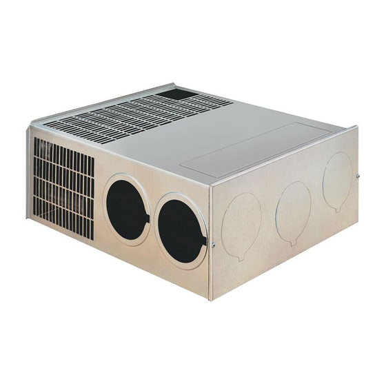
Page 17: Return Air Illustrations
Figure 18 NT-40 RETURN P-40 Return Air - The cabinet that the furnace may be installed in will have louvers or openings for the return air back to the furnace. When the furnace is installed, it is imperative that the return air louvers on the furnace cabinet opening are not obstructed. - Page 18 DUCTING Ducting - Suburban furnaces require that a minimum duct area be maintained throughout entire duct system including through the register. It is very important to adhere to the minimum duct area in order to keep the furnace from cycling on high limit and to assure proper operation of the sail switch (sometimes referred to as a microswitch.) NOTE: (Refer to the installation manual...
-
Page 28: Furnace Specifications (Sf, Sfv, Sh, And Shd-2542 Model Furnaces)
12 VDC Input Motor Static C.F.M. Model Description BTU/hr Type Gas Voltage Diameter Amp Draw Pressure Max. Direct DD-17DSI 17,000 PROPANE 12 VDC 3" Discharge 12,000 PROPANE 12 VDC 3" Ducted S - .1" wc NT-12S S - 122 Direct... - Page 29 6.5=2.5 in. SF-30/30F Ducted 30,000 PROPANE 12 VDC 3" .2" wc Motor 8.5=3 in. Motor 8.5=2.5 in. SF-35/35F Ducted 35,000 PROPANE 12 VDC 3" .2" wc Motor 9.4=3 in. Motor SF-42/42F Ducted 40,000 PROPANE 12 VDC 3" 11.5 .25" wc SFV-20/20F Ducted 20,000...
-
Page 30: Sequence Of Operation (Time Delay Relay Equipped Furnaces)
SEQUENCE OF OPERATION For Furnaces Equipped With Time Delay The thermostat controls the operating circuit to the furnace by reacting to room temperature to open and close a set of contact points which allows current to flow to the ON and OFF switch then to the relay. -
Page 31: Sequence Of Operation (24 Vac Fan Control Module Board (520947)
The wall thermostat controls the operation of the furnace by reacting to room Start temperature, this allows current to flow through the On/Off switch to the module board. The module board constantly checks for a minimum 9.5 volts. If there is not 9.5 volts, the module board will go into a stand by mode until adequate power is supplied. - Page 32 The module board will then verify that the sail switch circuit is closed and motor is up 15 Seconds Purge to speed. If this circuit remains open blower motor will run continuously until sail switch Cycle closes. The module board checks that the gas valve relay contacts (which are located on the module board) are open before the ignition sequence starts.
- Page 33 When the thermostat has reached its set point and the demand for heat ends, the gas valve will be de-energized and the flame will go out. The post combustion purge period of 90 seconds begins. When it times out, the blower motor output is removed, and the blower stops. TROUBLE SHOOTING GUIDE SUBURBAN RV FURNACES with TIME DELAY 12 VDC HEATING SECTION...
- Page 34 Replace the time delay relay. NOTE: On some models, sail switch is before limit switch. System Ok TROUBLE SHOOTING GUIDE SUBURBAN RV FURNACE with FAN CONTROL MODULE BOARDS 12 VDC HEATING SECTION Check thermostat wire connections, Clean points, secure loose <...
- Page 35 System Ok SERVICE HINTS, DIAGNOSIS, AND CORRECTIVE MEASURES FOR THE IGNITION SYSTEMS OF SUBURBAN 24 VOLT ELECTRONIC IGNITION GAS FURNACES WITH TIME DELAY Be sure the electrode assembly screws are snug at all times, CAUTIONS: especially after the electrode has been removed and reinstalled.
- Page 36 between electrode and ground to insure no sparking to sensor. Sparking to sensor will damage the module board. The electronic ignition system is made up of three main parts; the module 3. The module board also performs the lockout function in cases where the board, the electrode assembly, and the electrode wire.
- Page 37 isolating the furnace from the coach gas system will determine Disconnect gas bottle and drain it completely dry of all gas if the gas system is responsible. This isolation procedure can and all moisture. be done by connecting a separate upright bottle, regulator and Disconnect and blow out all gas lines completely dry.
- Page 38 Figure 23 Remote Flame Sense With Time Delay Figure 24 Local Flame Sense ( NT Models ) With Time Delay Fan Control Board Figure 25 (SF-20/25/30/35/42F)
- Page 39 Figure 26 Local Flame Sense (SF Models) With Time Delay Figure 27 Fan Control Board (NT-12/16/20S and SE)
- Page 40 Figure 28 Fan Control Board (NT-24/30/34SP and NT-40) Figure 29 Fan Control...
- Page 41 P-30S Figure 30 Fan Control Board P-40...
-
Page 42: Furnace Removal
FURNACE REMOVAL To replace parts or service the SUBURBAN family of RV furnaces, it is necessary to follow these steps: DD-17DSI Turn off gas and power, then disconnect gas and power supply at the furnace. Label wires as necessary. Remove the vent cap assembly by removing applicable screws. -
Page 43: Sf, Sh And Shd-2542 Electrode Gap Specifications & Positioning
Rewire applicable wires and perform a leak test on all fittings. Perform a drop pressure test. SF-20/25/30/35/42F, SFV-20/25/30/35/42F and SH-35/42F Turn off gas and power, then disconnect gas and power supply at the furnace. Label wires as necessary. Remove the vent cap assembly by removing applicable screws. Remove the cabinet front two (2) screws. - Page 44 Figure 31 NT ELECTRODE GAP SPECIFICATIONS AND POSITIONING To assure consistent ignition of the burner, it is important for the electrode to be positioned properly over the top of the burner. When replacing the electrode, or should you be experiencing ignition type problems, the electrode should be positioned as outlined in the drawing.
-
Page 45: Maintenance
1/8" spark gap between electrode and ground. 1/4" spark gap between ground and flame sensor. Maintain electrode position of 3/16" over burner ports. Figure 33 REMOTE FLAME SENSE MAINTENANCE Preventative maintenance is essential if an RV owner is to have reliable, safe operation of his furnace. Two important areas to watch closely in order to assure safe, reliable operation are the venting and the main burner. - Page 46 Figure 36 Figure 37...
-
Page 47: Cautions & Safety Information
CAUTIONS & SAFETY INFORMATION Never use a battery charger to power or test an electronic ignition furnace as they sometimes provide more than 14.5 DC Volts that could damage the module board. Never operate the furnace with the electrode wire disconnected nor with the electrode assembly removed from the furnace. Never use a screwdriver on any part of the electrode assembly while the furnace is in operation. - Page 48 SUBURBAN MANUFACTURING COMPANY 676 Broadway Street Dayton, Tennessee 37321 423-775-2131 Fax: 423-775-7015 www.rvcomfort.com E-mail: info1@suburbanmfg.com 2007...