Pioneer VSX-530-K Service Manual
Hide thumbs
Also See for VSX-530-K:
- Operating instructions manual (54 pages) ,
- Quick start manual (17 pages) ,
- Reference manual (27 pages)
Table of Contents
Advertisement
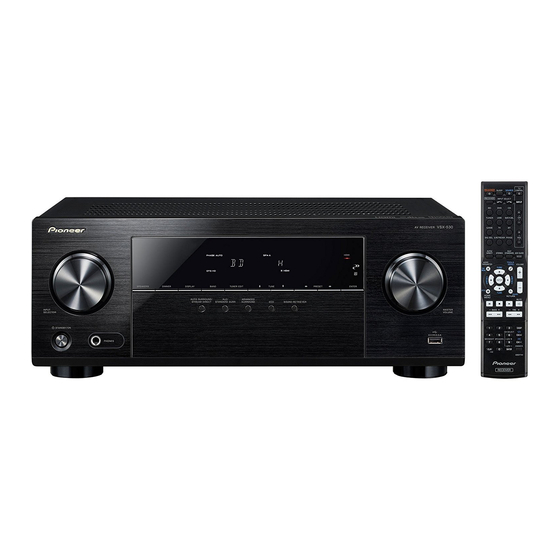
AV Receiver
VSX-530-K
VSX-430-K
THIS MANUAL IS APPLICABLE TO THE FOLLOWING MODEL(S) AND TYPE(S).
Model
Type
VSX-530-K
CUXEVSM
VSX-430-K
SYXEV8
This service manual should be used together with the following manual(s).
Model No.
VSX-523-K
For SPECIFICATIONS and PANEL FACILITIES, refer to the operating instructions.
PIONEER ELECTRONICS (USA) INC. P.O. Box 1760, Long Beach, CA 90801-1760, U.S.A.
PIONEER EUROPE NV Haven 1087, Keetberglaan 1, 9120 Melsele, Belgium
PIONEER ELECTRONICS ASIACENTRE PTE. LTD. 253 Alexandra Road, #04-01, Singapore 159936
Power Requirement
AC 120 V
AC 220 V to 230 V
Order No.
RRV4418
VSX-523-K/CUXESM
1-1, Shin-ogura, Saiwai-ku, Kawasaki-shi, Kanagawa 212-0031, Japan
2015
VSX-530-K
Remarks
K-ZZZ JULY
ORDER NO.
RRV4598
Remarks
2015 Printed in Japan
Advertisement
Table of Contents

Related Manuals for Pioneer VSX-530-K


Summary of Contents for Pioneer VSX-530-K
- Page 1 For SPECIFICATIONS and PANEL FACILITIES, refer to the operating instructions. 1-1, Shin-ogura, Saiwai-ku, Kawasaki-shi, Kanagawa 212-0031, Japan PIONEER ELECTRONICS (USA) INC. P.O. Box 1760, Long Beach, CA 90801-1760, U.S.A. PIONEER EUROPE NV Haven 1087, Keetberglaan 1, 9120 Melsele, Belgium PIONEER ELECTRONICS ASIACENTRE PTE. LTD. 253 Alexandra Road, #04-01, Singapore 159936...
-
Page 2: Exploded Views And Parts List
(In the case of no amount instructions, apply as you think it appropriate.) 1.1 PACKING SECTION Poly bag packing style Tape (clear) Cord AC Safety Brochure SPEAKER CAUTION Sheet Dry cell batteries (AAA size IEC R03) VSX-430-K/SYXEV8 only PE sheet VSX-530-K... - Page 3 See Contrast table (2) 8 Cushion Snow 423 6230213384100S 9 • • • • • NSP 10 Warranty Card ARY7172 (2) CONTRAST TABLE VSX-530-K/CUXEVSM and VSX-430-K/SYXEV8 are constructed the same except for the following: VSX-530-K VSX-430-K Mark Symbol and Description /CUXEVSM /SYXEV8...
- Page 4 VSX-530-K/CUXEVSM only VSX-430-K/SYXEV8 only ×23 Binder Silicon adhesive Clamp (GYA1011) Binder HP plate Silicon grease (GEM1057)
- Page 5 30 Cushion 4050211605000SV 61 Heatsink 2120212168010S 62 BT Cover 4310216061100S 31 SP Screw Cushion 4050211745100SV (2) CONTRAST TABLE VSX-530-K/CUXEVSM and VSX-430-K/SYXEV8 are constructed the same except for the following: VSX-530-K VSX-430-K Mark Symbol and Description /CUXEVSM /SYXEV8 MAIN Assy 7028077921010...
- Page 6 Ex.2 When there are 3 effective digits (such as in high precision metal film resistors). 5.62 kΩ → → 5621 ..............RN1/4PC 562 × 10 5 6 2 1 CONTRAST TABLE VSX-523-K/CUXESM, VSX-530-K/CUXEVSM and VSX-430-K/SYXEV8 are constructed the same except for the following: VSX-523-K VSX-530-K VSX-430-K Mark Symbol and Description Remarks...
- Page 7 Although 7028073312010-IL, 7028077922010 and 7028077922020 are different and are NOT COMPATIBLE! Some components on these assy's are different. Since these different components are not available as service part, they are not listed. G-L, G-R and WG ASSEMBLIES There is no service parts. VSX-530-K...
-
Page 8: Pcb Parts List
PCB PARTS LIST • CONTRAST OF PCB ASSEMBLIES for VSX-530-K/CUXEVSM and VSX-430-K/SYXEV8 MAIN ASSY 7028077921010 and 7028077921020 are constructed the same with the exception of some components, including the following: Mark Symbol and Description 7028077921010 7028077921020 601 Tuner, FM/AM E903004100781S E903104100781S Note: This list is not complete. -
Page 9: Troubleshooting
Check connection betwwern CN201 on D-MAIN Assy (CPU Assy and CN201 on CPU Assy. CN201 pins 30, 31) Is the voltage +3.3 V? Check IC301 on CPU Assy or (CPU Assy replace CPU Assy. IC301 pin 2) Replace CPU Assy. VSX-530-K... - Page 10 MAIN Assy. (FRONT Assy C728 - side) replace FRONT Assy. Is the voltage 3.3 V? Check Q702, Q703, R777, R778 or (FRONT Assy C730 + side) replace FRONT Assy. Is damage in FLT701? Replace FRONT Assy. Replace FLT701. VSX-530-K...
- Page 11 Are the signal on AMP5 Assy Speaker out sound CP401 pin 1, 9? Check and repair FL or FR AMP circuit or replace AMP5 Assy. Check the problem analog signal line between input connector and IC1009 (Input selector IC) or replace MAIN Assy. VSX-530-K...
- Page 12 5 (SL), 3 (C), 1 (SW). 11 (SL),13 (C),15 (SW). Check and repair AMP circuit of problem Replace MAIN Assy Check the signal CN109 - CN110 channels or replace AMP5 Assy. or their peripheral circuit. or replace CONCT Assy. VSX-530-K...
- Page 13 This is just for general reference and does not including every single case. No Picture Check IC1200 on MAIN Assy or Composite in → No Composite out replace MAIN Assy. Rear HDMI in → No HDMI out Replace D-MAIN Assy. VSX-530-K...
- Page 14 AMP5 ASSY CPU ASSY MAIN ASSY MAIN ASSY REG ASSY...
- Page 15 CPU ASSY AMP5 ASSY TRANS_TEMP_DET AMP5 ASSY GND5 MET37 NTC ASSY MAIN ASSY...
- Page 16 3 Turn on the power to the Bluetooth capable device that you wish to pair with, and perform pairing procedure on it. Note • This unit will be displayed as “Pioneer AVR” on all Bluetooth capable devices that you have. Pairing will start.
-
Page 17: Each Setting And Adjustment
6. Press the Reset button of the updating jig for updating. 7. Click on "OK" 8. 2. Specify the software file to be updated. Click on "Open" to open the File Selection window. Select Intel Hex files (*.hex) in File Type. VSX-530-K... - Page 18 COM PORT setting, start updating again from Step 1. 10. Turn the main unit off then disconnect the updating jig for updating. 11. Perform Factory Reset on the main unit. VSX-530-K...
-
Page 19: Schematic Diagram
5. SCHEMATIC DIAGRAM SPEAKER TERMINAL F 1/2 MAIN ASSY F 2/2 (VSX-530-K/CUXEVSM: 7028077921010) (VSX-430-K/SYXEV8: 7028077921020) 1N-J 1N-J 1N-J 1N-J 1N-J C-CAP:SYXEV8 : 22N CUXEV :10N C609R 10/50 C614 C612 C611R 100N-K 4N7-K NJM41050VT LOGIC TABLE R1203 R1204 R1200 C618 C611L... - Page 20 F 2/2 MAIN ASSY (SW) (VSX-530-K/CUXEVSM: 7028077921010) (VSX-430-K/SYXEV8: 7028077921020) C474 100P-J D418 LBAS16HT1G D419 LBAS16HT1G C407 82P-J Q402 (FL) C401 (FL) R404 INC2001AC1 10/50 R409 C409 (SL) C406 Q405 82P-J (SL) R415 R470 INC2001AC1 10/50 R420 R462 C460 R466 10/50...
- Page 21 F 1/4 D-MAIN ASSY (7028077971010) V+1R1_HD H+3.3V V+5_R1 JA9601 C9622 VA9602 HD043-F19G1BY-A R9679 BK1005 HS121-B BK1005 HS121-B H+3.3V R9601 F 4/4 HPD_1 H+5V Q9606 C9623 DTC114YUA GND-H VA9603 C158 330P/50 Q9607 1N-K DTC124EUA R9645 R110 R111 SDA_1 R9646 SCL_1 R101 240K-F VA9604 MP2143DJ...
- Page 22 F 2/4 D-MAIN ASSY (7028077971010) R2131 COAX_IN COAX F 4/4 R2123 OPT_IN R2187 R2125 L2016 C1563 C1864 0.01U/25 L2013 D+3.3V 2.2UH C1866 330P/50 L1817 BK1005 HS121-B C2133 IC1812 10N-K GND-H R1901 C2155 330P-J L2014 LBC2012T-4.7UH R1951 GND-H ARCSPDIF. TC7SH08FUS1 GND-H L2012 C1562 R1895...
- Page 23 F 3/4 D-MAIN ASSY The > mark found on some component parts indicates the importance of the safety factor of the part. (7028077971010) Therefore, when replacing, be sure to use parts of identical designation. R2304 R2306 R2307 IC1606 SMPS+5.6V CP2006 TPS2051CDBVR Vo=5.053V 20010WS-05...
- Page 24 F 4/4 D-MAIN ASSY (7028077971010) R224 R225 H+3.3V R226 H+5V H+3.3V_FET_ON GND-H HPD_4 HPD_3 F 1/4 HPD_2 HPD_1 PSDA PSCL 74 73 R2038 XHDOSDIRQ1 R2037 XHDSCRST R200 R215 R2062 SUB_RXD CEC_IO R216 R2064 SUB_TXD R201 R197 R198 C2156 4N7-K C104 R199 C2345 4N7-K...
- Page 25 F 4/4 CN204 F 4/4 CPU ASSY CN201 (VSX-530-K/CUXEVSM: 7028077931010) (VSX-430-K/SYXEV8: 7028077931020) _BURRING_ R229 BKT201 BKT203 R210 GND2 IC301 JP81 AZ1117CH-3.3TRG1 JUMPER R230 GNDCH J252 JP36 J253 BKT202 JUMPER SPTE_0.8T GNDU C202 10N-K -VF(-30V) CPU_+3.3V C201 C242 100N-K 10N-K R336...
- Page 26 NTC ASSY BT ASSY (7028077924010) (7028077941010) R289 BT_+5V GND5 MET37 SC52136-031A DHTH1608103J3435HST F 1/2 DHTH1608103J3435HST C450 R290 C466 10N-K C457 R291 R295 ANALOG_L- C455 10000N-K R293 R294 BT_L BT_L C458 R292 R325 C490 R296 1/50-Z8155 ANALOG_L+ BT_GNDA 10000N-K BT_R R321 H_+5V C451 CN210...
-
Page 27: Pcb Connection Diagram
6. PCB CONNECTION DIAGRAM SIDE A SIDE A NOTE FOR PCB DIAGRAMS : 2. View point of PCB diagrams. MAIN ASSY Connector Capacitor 1. The parts mounted on this PCB include all necessary parts for several destinations. SIDE A For further information for respective destinations, be sure to check with the schematic diagram. - Page 28 SIDE B SIDE B MAIN ASSY IC1200 Q416 Q417 IC401 Q425 Q428 Q426 IC1009 IC403 Q427 Q419 IC402 Q402 Q405-Q407 Q410 CP110...
- Page 29 SIDE A SIDE B D-MAIN ASSY D-MAIN ASSY R9682 R9680 R9679 C1700 C1699 JA9603 JA9604 JA9602 JA9601 JA1601 R1669 R9609 C1696 VA9665 R1668 Q9610 R1667 Q9612 Q9613 Q9611 R1666 Q9606 5.COAX IN Q9608 Q9607 Q9609 C1704 4.GND-H C1686 3.3.3V C9319 2.GND-H IC1605 TPS2051CDBVR...
- Page 30 SIDE A SIDE B CN106 CN704A CN206 CN704B CN704B CN206 CPU ASSY CPU ASSY 15.-VF 14.-VF 13.GNDU 12.GNDU 11.HP_R 10.HP_R 9.HP_AGND 8.HP_AGND 7.HP_L 6.HP_L 5.TRANS_TEMP_DET 4.DC_DET4 3.DC_DET3 2.DC_PRO 1.VIDEO_MUTE IC301 Q211 IC204 Q209 Q212 Q216 Q217 Q210 33.GNDU Q215 32.GNDU 31.SMPS+5.6V 30.SMPS+5.6V 29.D+5V_FETON...
- Page 31 6.4 NTC and BT ASSYS SIDE A SIDE A BT ASSY NTC ASSY BKT1 CN210 GND5 IC112 IC114 IC115 Q130 SIDE B SIDE B NTC ASSY BT ASSY Q131 VSX-530-K...