Greenheck FSD Series Installation, Operation And Maintenance Instructions
1 1/2 and 3 hour fire & combination fire smoke dampers with factory installed sleeve and actuator, vertical and horizontal mount
Hide thumbs
Also See for FSD Series:
- Installation, operation and maintenance manual (2 pages) ,
- Installation instruction booklet (52 pages) ,
- Manual (12 pages)
Table of Contents
Advertisement
Quick Links
- 1 Pre-Installation Guidelines
- 2 Clearances Required between Fire Damper Sleeves and Wall/Floor Openings
- 3 Installation
- 4 Sleeve Length and Wall Thickness
- 5 Securing the Damper/Sleeve Assembly to Wall and Floor Openings
- 6 Recommended Preparation of Openings in Wood and Metal Stud Walls
- Download this manual
reCeIVInG anD HanDlInG
Upon receiving dampers, check for both obvious and
hidden damage. If damage is found, record all necessary
information on the bill of lading and file a claim with
the final carrier. Check to be sure that all parts of the
shipment, including accessories, are accounted for.
Dampers must be kept dry and clean. Indoor storage
and protection from dirt, dust and the weather is highly
recommended. Do not store at temperatures in excess of
100°F.
saFety WarnInG:
Improper installation, adjustment, alteration,
service or maintenance can cause property damage,
injury or death. read the installation, operating,
and maintenance instructions thoroughly before
installing or servicing this equipment.
This manual is the property of the owner, and is required
for future maintenance. Please leave it with the owner
when the job is complete.
Due to continuing research, Greenheck reserves the right to change specifications without notice.
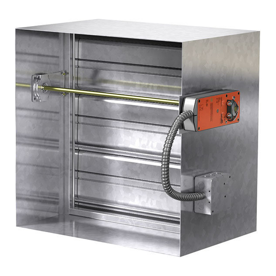
Typical Actuator
RRL Control Device
Standard
Installation,Operation and
Maintenance Instructions
for FsD-xxx, DFD-xxx,DFDtF-xxx
CFsD-xxx,seDFD-xxx, seFsD-xxx,
Imo-xxx, anD ssFsD-xxx serIes
Fire & Combination Fire smoke Dampers
(with factory installed sleeve and actuator)
FSD-XXX, SEFSD-XXX, SSFSD-XXX, DFD-XXX, SEDFD-XXX,
and CFSD-XXX Series Dampers are intended for installation
in accordance with combination fire smoke damper
requirements established by:
national Fire protection association
NFPA Standards 90A, 92A, 92B & 101
BoCa national Building Codes
ICBo uniform Building Codes
IBC International Building Codes
sBCCI standard Building Codes
new york City (MEA listing #260-91-M)
California state Fire marshal (Listing #3225-0981:103)
and (Listing #3230-0981:104) - FSD models; (Listing #3225-
0981:103) - DFD models; (Listing #3230-0981:105) and (Listing
3225-0981:106) - CFSD models; (Listing #3225-0981:109) and
(Listing 3230-0981:110 ) - SSFSD models
"ul ClassIFIeD (see complete marking on product)"
"ul ClassIFIeD to Canadian safety standards (see
complete marking on product)"
UL Standard 555 & 555S (Classification #R13317)
InstallatIon supplements
Refer to the appropriate Greenheck installation
supplements for special requirements:
•
Shaftwall Supplement
•
Drywall Supplement
•
Wood Supplement
•
Smoke Detector Supplement
•
Tunnel Corridor Supplement
•
Single Side Retaining Angle Supplement
•
Grille Installation Supplement
•
Field Installed Sleeve Supplement
Warranty
Greenheck warrants this equipment to be free from
defects in material and workmanship for a period of one
year from the purchase date. Any units or parts which
prove to be defective during the warranty period will
be repaired or replaced at our option. Greenheck shall
not be liable for damages resulting from misapplication
or misuse of its products. Greenheck will not be
responsible for any installation or removal costs.
Greenheck will not be responsible for any service work
or backcharges without prior written authorization.
part #461336
1
⁄
and 3 Hour
1
2
Vertical and Horizontal mount
Advertisement
Table of Contents

Related Manuals for Greenheck FSD Series


Summary of Contents for Greenheck FSD Series
- Page 1 Please leave it with the owner Greenheck will not be responsible for any service work when the job is complete. or backcharges without prior written authorization. Due to continuing research, Greenheck reserves the right to change specifications without notice.
-
Page 2: Table Of Contents
table of Contents Pre-Installation Guidelines ...................2 Electrical Guidelines .....................3 Installation ......................3-8 • ..3 Clearances Required Between Fire Damper Sleeves and Wall/Floor Openings • ..............4 Sleeve Length and Wall Thickness • ................4 Duct to Sleeve Connections • .....5 Securing the Damper/Sleeve Assembly to Wall and Floor Openings •... -
Page 3: Electrical Guidelines
CautIon ! Verify power before wiring actuator. Greenheck is not responsible for any damage to, or failure of the unit caused by incorrect field wiring. saFety DanGer ! : to avoid causing death or serious bodily harm to building occupants, follow all instructions carefully. -
Page 4: Sleeve Length And Wall Thickness
2. sleeVe lenGtH anD Wall tHICKness Insert the sleeved damper assembly into the prepared opening, to appropriate depth (refer to label on outside of sleeve for location of damper in wall; see Page 3, Dimension A and Detail 1, Fig. 1). Recommended maximum and minimum insertion depth can be exceeded if: The operation of the damper is not impeded... -
Page 5: Securing The Damper/Sleeve Assembly To Wall And Floor Openings
Vertical mount 4. seCurInG tHe Damper/sleeVe assemBly to Wall anD Floor openInGs (continued) Maximum Max Overall Size Damper Single-Section for Multi-Section A minimum of two connections per side, top, and Model Size Dampers bottom, 12 in. O.C. maximum for openings of 48 in. W 36 x 36 or 32 x 48 64 x 48 DFD-230... -
Page 6: Recommended Preparation Of Openings In Wood And Metal Stud Walls
7. ConneCtIon anD operatIon oF temperature ratInGs response DeVICes (continued) Integral switch type: Single Pole, double throw tor - The TOR (temperature override device) option electrical Capacity: 10 Amps, hp, 120 or 240 Vac incorporates two thermostats with fixed settings (usually 165°F Amp, 125 Vdc;... -
Page 7: Breakaway Connections
Fig. 10 9. Breakaway Connections traditional Breakaway style transverse Joints Transverse joints illustrated at right have always been approved as breakaway connections. • The breakaway connections shown to the right can be applied maximum of (2) #10 sheet metal screws on each side and on the bottom located in the center of the slip pocket and penetrating both sides of the slip pocket. -
Page 8: Maintenance
(see Damper Maintenance) Heat RRL or TOR sensor Push reset button located on backside tripped of RRL or TOR. No power supplied to the actuator Damper does not operate Copyright © 2005 Greenheck Fan Corporation IOM 461336 FSD Rev. 8 May 2005...