Table of Contents
Advertisement
Owner / Operator Manual
THIS DOCUMENT CONTAINS IMPORTANT INFORMATION
This Manual must be read and understood before installing or
operating this equipment
Release Date: October 28, 2005
Revision Date: December 22, 2005
Publication Number: 630460146OPR
Revision: A
www.cornelius.com
IMPORTANT:
TO THE INSTALLER.
It is the responsibility of
the Installer to ensure that
the water supply to the
dispensing equipment is
provided with protection
against backflow by an air
gap as defined in
ANSI/ASME A112.1.2-1979;
or an approved vacuum
breaker or other such
method as proved effective
by test.
Water pipe connections
and fixtures directly
connected to a potable
water supply shall be
sized, installed, and
maintained according to
Federal, State, and Local
Codes.
IMI Cornelius Inc.
Advertisement
Table of Contents

Related Manuals for Cornelius Xtreme ICE Series


Summary of Contents for Cornelius Xtreme ICE Series
- Page 1 Federal, State, and Local Codes. THIS DOCUMENT CONTAINS IMPORTANT INFORMATION This Manual must be read and understood before installing or operating this equipment Release Date: October 28, 2005 IMI Cornelius Inc. Revision Date: December 22, 2005 Publication Number: 630460146OPR Revision: A www.cornelius.com...
-
Page 7: Table Of Contents
TABLE OF CONTENTS Model and Serial Location ....... . . Xtreme Ice Machine . - Page 8 Maintenance ..........General Ice Machine Inspection .
-
Page 9: Model And Serial Location
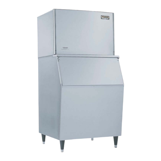
MODEL AND SERIAL LOCATION XTREME ICE MACHINE Condenser Discharge Air Deflector (as required)* Bin Adapter (as required)* Model/Serial Number Location *Bin adapters and condenser discharge air deflector may be equipped depending on your location or the size of the storage bin. Record the model number and the serial number of your ice equipment. -
Page 10: Specifications
SPECIFICATIONS The following table contains equipment specification information for the Ice Machines. Model 322/330 322/330 522/530 522/530 522/530 UNIT Volts Phase Hertz No. Wires 2+Ground 2+Ground MIN. CIRCUIT Amps MAX. FUSE SIZE Amps REFRIGERANT Type R404a R404a R404a R404a R404a R404a R404a R404a... - Page 11 XAC 330 XAC 522 XAC 530 Model 1444 1444 1444 1844 1844 1844 UNIT Volts Phase Hertz No. Wires 2+Ground 2+Ground MIN. CIRCUIT Amps MAX. FUSE SIZE Amps REFRIGERANT Type R404a R404a R404a R404a R404a R404a R404a R404a R404a R404a Weight (oz) Weight (g) 1900...
-
Page 12: General
S Refrigerant Charge: See Nameplate Microban IMI Cornelius Ice Maker Product includes Microbanr Built–In Product Protection to inhibit the growth of odor and stain causing bacteria, mold, and mildew. This will improve the units per- formance between cleaning, but should not exclude the standard cleaning process. Please refer to the Maintenance section of this manual for proper cleaning procedures. -
Page 13: Installation Instructions
INSTALLATION INSTRUCTIONS Installation and start-up of the equipment should be performed by the distributor or the dealer’s professional staff. LOCATION OF EQUIPMENT For maximum performance the location should be away from heat sources such as ovens, direct sunlight, hot air discharge, etc. To reduce cost of maintenance and loss of efficiency, avoid placing air-cooled equipment in areas where grease, flour and other airborne contaminants are present. -
Page 14: Equipment Set-Up
EQUIPMENT SET-UP The following steps refer to the set-up of the ice bin and the cuber: 1. Remove the bin from its carton, place it on its back and install the legs into the bottom of the bin. Bins must be installed on legs or sealed to the floor with RTV-732 sealant. -
Page 15: Dispenser Installation
DISPENSER INSTALLATION 1. The proper cuber/dispenser installation package should be ordered. This package will include gasket mate- rial, and hold-down bracket, and bin stat. 2. RTV applications (See Fig. 2 above). If the ice bin is full, new ice will not be able to drop. Instead it blocks the evaporator curtain open and no additional ice is made. -
Page 16: Electrical
ELECTRICAL 1. All wiring and connections must conform to national and local electrical codes. 2. Wire size and circuit protection must conform to specifications and cuber must be on a separate electrical circuit. 3. Strain relief connectors must be used at the junctions box of the control box and the cuber. 4. -
Page 17: Operation
OPERATION UNIT SELECTION 1. The unit selection dip switches tell the microprocessor the correct water level difference for harvest and the number of proximity switch circuits to monitor. 2. The unit selection dip switches are a series of 3 switches that can be placed in either the ON or OFF posi- tion. -
Page 18: Start Up Sequence (Primary)
START UP SEQUENCE (PRIMARY) 1. Check all connections. 2. Turn on the main power switch, the red LED will flash (6) times, then be on steady for (4) seconds. 3. The unit will go through a 45 second hot gas defrost to remove any ice that might be on the evaporator. NOTE: If there is a very large slab of ice on the evaporator you will need to push the manual harvest button to remove it. -
Page 19: Freeze Cycle
FREEZE CYCLE 1. Ten seconds after the fill valve turns off, the microprocessor records the water level. 2. Using the recorded high water level, the calibration level and the ice thickness level, the microprocessor calculates a harvest level. 3. The microprocessor monitors the water level until it reaches the harvest level. As ice builds on the evaporator the water level in the water pan drops. -
Page 20: Ice Production Check
ICE PRODUCTION CHECK If air cooled, take air temperature at the intake of the condenser, 2I from the condenser fins, and Incoming wa- ter temperature at the outlet of the “fill” valve.* Cycle time (CT) = freeze time plus harvest time, in minutes and seconds. 1440 divided by CT = number of cycles per 24 hours. -
Page 21: Flashing Code For Self Diagnostics (1400'S And 1800'S)
FLASHING CODE FOR SELF DIAGNOSTICS (1400’s and 1800’s) Delay LED Error LED High Condenser Temperature Warning High Condenser Temp. Shutdown Low Condenser Temperature Delay Failed Freeze Time Out Shutdown Water Inlet Warning Failed Harvest Shutdown Failed Water Temperature Shutdown Failed Water System Shutdown End of Clean Cycle Shutdown Open Water Thermistor Shutdown Open Condenser Thermistor Shutdown... -
Page 22: Harvest Button
HARVEST BUTTON Manual Harvest 1. At any time after secondary start up, the machine can be put into the harvest cycle by depressing the har- vest button. 2. Pressing the harvest button will tell the microprocessor to skip directly to the harvest cycle. 3. -
Page 23: Maintenance
MAINTENANCE SEMI-ANNUAL MAINTENANCE GENERAL ICE MACHINE INSPECTION CLEANING THE EXTERIOR CLEANING THE CONDENSER – AIR-COOLED WATER-COOLED INTERIOR CLEANING – CLEANING PROCEDURES SANITIZING PROCEDURES GENERAL ICE MACHINE INSPECTION S Check all water fittings and tubes for leaks. Also, make sure the refrigeration tubing is not rubbing or vibrat- ing against other tubing panels, etc. -
Page 24: Water-Cooled Condenser (And Regulating Valve)
1. Clean the outside of the condenser with a soft brush or vacuum with a brush attachment. Brush or wash condenser from top to bottom, not from side to side. Be careful not to bend the fins. Shine a flashlight through the condenser to check for dirt between the fins. -
Page 25: Sanitizing The Water System And The Evaporator
FIG. 10 INNER WATER DISTRIBUTOR WATER DIST. ASSEMBLY ”O” RING SCALE INNER WATER DISTRIBUTOR BARB ”O” RING FIG. 11 5. Return the water curtain(s) to their proper operating positions. 6. Add 5 oz. for the 300’s, 8 oz. for the 500’s, 600’s, and 800’s, 12 oz. for the Dual Evaporator, and 16 oz. for the Quad of “Calgon Nickel Safe”... - Page 26 630460146OPR December 22, 2005...
-
Page 27: Before Calling For Service
BEFORE CALLING FOR SERVICE If a problem arises during the operation of your ice machine, follow the checklist below before calling for ser- vice. CHECKLIST Problem Probable Cause Remedy ICE MACHINE DOES NOT No electrical power to ice Replace fuse, reset circuit OPERATE machine. -
Page 28: Warranty
WARRANTY IMI Cornelius Inc. warrants that all equipment and parts are free from defects in material and work- manship under normal use and service. For a copy of the warranty applicable to your Cornelius prod- uct, in your country, please write, fax or telephone the IMI Cornelius office nearest you (www.cornelius.com). - Page 29 IMI CORNELIUS INC. WWW.CORNELIUS.COM...