Table of Contents
Advertisement
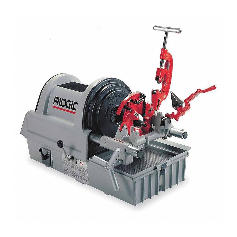
1822-I Pipe and Bolt Threading Machine
DO NOT use a sling through the spindle tube
CAUTION
only.
Figure 6 – Sling Transportation
Machine Inspection
WARNING
To prevent serious injury, inspect your Threading
Machine. The following inspection procedures
should be performed on a daily basis:
1. Make sure threading machine is unplugged and the
control switch is set to the OFF position (Figure 7).
2. Clean the chuck jaws with a wire brush.
3. Inspect the jaws for excessive wear or damaged
teeth. Refer to the Maintenance Instructions if they
need to be replaced.
4. Make sure the foot switch is present and attached to
the Threading Machine (Figure 7).
WARNING
Do not operate the Threading Machine
without a foot switch.
5. Inspect the power cord and plug for damage. If the
plug has been modified, is missing the grounding
pin, or if the cord is damaged, do not use the Thread-
ing Machine until the cord has been replaced.
8
RIDGID Center-Lock Chuck
Rear Centering/Front Gripping
Rear Cover
Top Cover
Control
Switch
Transmission
Lever
Foot Switch
Figure 7 – 1822-I Threading Machine
6. Inspect the Threading Machine for any broken, miss-
ing, misaligned or binding parts as well as any other
conditions which may affect the safe and normal op-
eration of the machine. If any of these conditions
are present, do not use the Threading Machine until
any problem has been repaired.
7. Lubricate the Threading Machine if necessary ac-
cording to the Maintenance Instructions.
8. Use tools and accessories that are designed for your
Threading Machine and meet the needs of your ap-
plication. The correct tools and accessories allow
you to do the job successfully and safely. Accessories
designed for use with other equipment may be haz-
ardous when used with this Threading Machine.
9. Clean any oil, grease or dirt from all handles and con-
trols. This reduces the risk of injury due to a tool or
control slipping from your grip.
10. Inspect the cutting edges of your tools and dies. If
necessary, have them replaced prior to using the
Threading Machine. Dull or damaged cutting tools
and dies can lead to binding, tool breakage and poor
quality threads.
Ridge Tool Company
No. 364 Cutter
Front Cover
Self-Opening
Drain Plug
Handwheel
No. 344
Reamer
Die Head
Chip Pan
Advertisement
Table of Contents

Related Manuals for RIDGID 1822-I


Summary of Contents for RIDGID 1822-I
- Page 1 1822-I Pipe and Bolt Threading Machine DO NOT use a sling through the spindle tube CAUTION only. RIDGID Center-Lock Chuck Rear Centering/Front Gripping No. 364 Cutter Front Cover No. 344 Reamer Rear Cover Top Cover Self-Opening Die Head Control Chip Pan...
- Page 2 11. Clean metal shavings and other debris from the chip sure 1460 Oil Pan Cover is removed. tray of the Threading Machine. Check the level and 6. If necessary, fill the reservoir with RIDGID Thread quality of the thread cutting oil. Replace or add oil if Cutting Oil.
- Page 3 1822-I Pipe and Bolt Threading Machine • Depress and hold the foot switch. Inspect the mov- To avoid equipment tip-overs, position WARNING the pipe supports under the workpiece. ing parts for misalignment, binding, odd noises or any other unusual conditions that may affect the 6.
- Page 4 1822-I Pipe and Bolt Threading Machine Speed Selection Chart 7. Tighten the feedscrew handle slowly and continu- ously until the pipe is cut. Do not force the cutter Size/Material Recommended RPM into the workpiece. ″ – 2″ Pipe ″ – 1″ Bolt 8.
- Page 5 1822-I Pipe and Bolt Threading Machine 8. Move die head to UP position. 9. With head in vertical position, rotate cam plate until roll pin on lock screw can be positioned in slot under size 9. Release foot switch and remove your foot from the bar.
- Page 6 1822-I Pipe and Bolt Threading Machine NOTE! High speed dies are recommended for thread- (Figure 13 – Model 816/817 Die Head) against the ing 1″ to 2″ pipe at 45 RPM. plunger knob (as shown). 1. Lay die head on bench with numbers face up.
- Page 7 1822-I Pipe and Bolt Threading Machine Operation Instructions Guide Post Using Geared Threaders Head Reference Lines (3) WARNING Drive Shaft Do not wear gloves or loose clothing when oper- ating Threading Machine. Keep sleeves and jack- ets buttoned. Do not reach across the machine or geared threader.
- Page 8 ″ to 4″ Pipe (45 RPM) 3. For straight threads, insert guide post with straight slot inward through die head to the gear case. 1. Adjust No. 141 Geared Threader and install on 1822-I Threading Machine. 4. With guide block in diagonal/straight slot, replace set screw.