Table of Contents
Advertisement
Quick Links
Advertisement
Table of Contents

Related Manuals for Ryobi RG-1250I


Summary of Contents for Ryobi RG-1250I
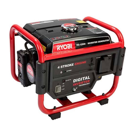
- Page 2 THANK YOU FOR BUYING A RYOBI INVERTER GENERATOR Your new inverter generator has been engineered and manufactured to Ryobi’s high standard of dependability, ease of operation and operator safety. Properly cared for, it will give you years of rugged, trouble free performance. If you use your inverter generator properly and only for what it is intended, you will enjoy years of safe, reliable service.
-
Page 3: Important Safety Instructions
IMPORTANT SAFETY INSTRUCTIONS The purpose of safety rules is to attract your DANGER: CARBON MONOXIDE. attention to possible dangers. The safety symbols Using a generator indoors CAN KILL and the explanations with them, require your YOU IN MINUTES. careful attention and understanding. The safety Generator exhaust contains high levels of carbon warnings do not by themselves eliminate any monoxide (CO), a poisonous gas you cannot see... - Page 4 IMPORTANT SAFETY INSTRUCTIONS Do not operate generator when you are tired or To prevent an electric shock, never operate the under the influence of drugs, alcohol, or machine in rain, snow or touch with wet hands. medication. Check the fuel system periodically for leaks. Seals The electrical output load must not exceed the and hoses should be checked for signs of maximum load stated on the rating plate.
- Page 5 IMPORTANT SAFETY INSTRUCTIONS For power outages, permanently installed Inspect the unit before each use for loose stationary generators are better suited for providing fasteners, fuel leaks, etc. Replace damaged parts. back-up power to the home. Even a properly Use only recommended or equivalent replacement connected portable generator can become parts and accessories.
-
Page 6: Specific Safety Rules
SPECIFIC SAFETY RULES WARNING: When this generator is used Check the ventilation hole inside the fuel tank cap to supply a building wiring system: the for debris. Do not block the vent. generator must be installed by a qualified Do not smoke when filling the generator with electrician and connected to a transfer switch as a unleaded fuel. - Page 7 DESCRIPTION 1. Fuel cap 9. Recoil starter grip 2. Fuel tank 10. Electronic engine switch 3. AC socket 11. Control panel 4. Choke lever 12. Fuel valve 5. Spark plug cap 13. Oil pressure alarm indicator 6. Muffler 14. Output indicator light 7.
-
Page 8: Pre-Operation Check
PRE-OPERATION CHECK CHECKING THE ENGINE OIL and do not use an oil/fuel mixture. Do not allow dirt WARNING. Running the generator with or water into the fuel tank. insufficient engine oil can cause serious engine damage. Engine oil should be replaced during regular maintenance or when the oil level is below the end of the dipstick. -
Page 9: Understanding The Control Panel
UNDERSTANDING THE CONTROL PANEL 1. AC socket which supplies rated output. B. lnterval Flash 2 times, high temperature protection. 2. Electronic engine switch. C. lnterval Flash 3 times, overload protection, 3. Oil pressure alarm indicator (Red). too many loads. A. lt will start flashing when the engine starts D. -
Page 10: Operation
OPERATION STARTING THE GENERATOR CAUTION. Always check the oil level before starting the engine (see Page 7). Before starting the engine make sure that all the electrical loads are disconnected from the generator AC outlet socket. 1. Turn the fuel valve to the ON position (Fig.6) 2. -
Page 11: Stopping The Generator
OPERATION STOPPING THE GENERATOR WARNING. In case of emergency, the easiest way to stop the generator is to directly put engine switch to OFF position. Avoid doing so in non-emergency circumstances as it carries the risk of damaging the generator. 1. -
Page 12: Checking/Cleaning The Air Filter
MAINTENANCE CHECKING/CLEANING THE AIR FILTER For proper performance and long life, keep air filters clean. 1. Using a screwdriver unscrew the two air filter connection screws located at the top and bottom of the air filter cover. Remove the cover and set aside (Fig.13). -
Page 13: Draining The Fuel Tank
MAINTENANCE CLEANING THE FUEL VALVE FILTER The fuel valve filter prevents dirt and water that may have gotten into the fuel tank from entering the carburetor. If the engine has not been run for a long time, the fuel valve filter should be cleaned before use. -
Page 14: Draining The Carburetor
STORAGE If the generator is not to be used or is to be stored for more than one month the following storage procedure should be carried out. Drain all the fuel from the fuel tank and the carburettor, ensure that all the fuel has been removed. -
Page 15: Maintenance Chart
Now that you have purchased your tool, should a need ever exist of repair or service, simply contact your nearest Ryobi Authorised Service Centre or other qualified service organistion. Be sure to provide all pertinent facts when you call or visit. - Page 16 SYMBOLS Some of the following symbols may be used on this tool. Please study them and learn their meaning. Proper interpretation of these symbols will allow you to operate the tool better and safer. SYMBOLS DESIGNATION/EXPLANATION Do not expose to rain or use in damp locations. To reduce the risk of injury, the user must read and understand the operator’s manual before using this product.
-
Page 17: Fault Chart
FAULT CHART CONDITION PROBABLE CAUSE CORRECTIVE ACTION Fill sump with No oil/ Low oil level correct oil Loose spark plug Tighten plug Insufficient Loose cylinder Tighten bolt compression head bolt Damaged gasket Replace gasket FUEL SYSTEM PROBLEMS Insufficient pulling Pull rope sharply speed for starting rope Foreign matter in... - Page 18 FAULT CHART CONDITION PROBABLE CAUSE CORRECTIVE ACTION Tripped circuit breaker Reset Poor connection or faulty lead Check and repair Indicator light ON. No AC output Broken recepticle Faulty circuit breaker Check and repair Indicator light OFF. Generator problem No AC output Output power too Engine RPM set too No load speed set...
- Page 19 NOTES...
- Page 20 NOTES...