Table of Contents

Related Manuals for Ryobi RIG2000PC


Summary of Contents for Ryobi RIG2000PC
- Page 1 RIG2000PC DIGITAL INVERTER GENERATOR OPERATOR'S MANUAL (ORIGINAL INSTRUCTIONS) It is essential that you read the instructions in this manual before Important! assembling, maintaining and operating this machine. Subject to technical modifications.
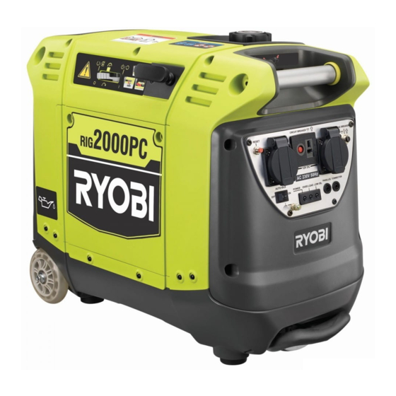
- Page 2 DESCRIPTION 1. Engine cover 20. Wheel 2. Engine/choke lever/on-off switch/fuel valve lever 21. Funnel 3. Starter grip and rope 22. Oil cap/dipstick 4. Fuel cap 23. Off 5. Parallel kit terminal 24. On 6. 10 Amp, AC circuit breaker 25. Engine/choke lever in off position 7.
- Page 3 Fig. 2 Fig. 3 Fig. 4 Fig. 5 Fig. 6 Fig. 7...
- Page 4 Fig. 9 Fig. 8 Fig. 10 Fig. 11...
- Page 5 Fig. 13 Fig. 12 Fig. 14 Fig. 15...
-
Page 6: Important Safety Instructions
be followed during installation and maintenance of the INTRODUCTION generator and batteries. This product has many features for making its use Do not connect to a building’s electrical system unless more pleasant and enjoyable. Safety, performance, and the generator and transfer switch have been properly dependability have been given top priority in the design installed and the electrical output has been verifi... -
Page 7: Specific Safety Rules
Position the unit on level ground, stop engine, and allow The frame of the generator shall be connected to cool before refuelling. to an approved grounding electrode. Failure to isolate the generator from power utility can result Loosen fuel cap slowly to release pressure and to keep ... - Page 8 2.5 mm this should not exceed 100 m. The generating set must not be connected to other power sources except another RIG2000PC with the RIGPC1000 Parallel Cable (sold separately). Save these instructions. Refer to them frequently and ...
- Page 9 SYMBOLS Some of the following symbols may be used on this tool. Please study them and learn their meaning. Proper interpretation of these symbols will allow you to operate the tool better and safer. SYMBOLS DESIGNATION/EXPLANATION Do not expose to rain or use in damp locations. To reduce the risk of injury, the user must read and understand the operator’s manual before using this product.
- Page 10 SERVICE Servicing requires extreme care and knowledge and should be performed only by a qualifi ed service technician. For service, contact your nearest authorised service centre for repair. When servicing, use only original manufacturer’s replacement parts, accessories and attachments. WARNING: Observe all normal safety precautions related to avoid electrical shock.
- Page 11 will automatically shut off the engine if oil level falls below SAFETY LABELS a safe limit. The information below can be found on the generator. For your safety, please study and understand all of the HOT SURFACE WARNING labels before starting the generator. If any of the labels come off the unit or become hard to read, contact the authorised service centre for replacement.
- Page 12 ELECTRICAL EXTENSION CORD CABLE SIZE Refer to the table below to ensure the cable size of the extension cords you use are capable of carrying the required load. Inadequate size cables can cause a voltage drop, which can damage the appliance and overheat the cord. Load in Watts Maximum Allowable Cord Length Current in...
-
Page 13: Product Specifications
Never add more loads than the generator capacity. Take ELECTRICAL special care to consider surge loads in generator capacity as previously described. GENERATOR CAPACITY CAUTION: Make sure the generator can supply enough continuous Do not overload the generator’s capacity. Exceeding the (running) and surge (starting) watts for the items you will generator’s wattage/amperage capacity can damage the power at the same time. - Page 14 lead acid batteries with the generator. Fuel tank volume 3.8 L NOTE: Only use battery charging cable to charge vented Run time (half load) 5 hours wet lead acid batteries. Run time (full load) 3 hours CARRY HANDLES Generator The generator is equipped with two carry handles for easy transport.
-
Page 15: Operation
choke lever) to start the generator’s engine. Never use a generator inside homes, garages, crawlspaces, or other partly enclosed areas. Deadly levels of carbon monoxide can build up in these ASSEMBLY areas. Using a fan or opening windows and doors does NOT supply enough fresh air. - Page 16 gasoline before fueling the tank rather than adding Overload: fuel stabilizer directly into the generator’s fuel tank. The overload indicator will light if the generator’s wattage/ Replace and secure the fuel tank cap. amperage capacity is exceeded. To reset the generator, ...
-
Page 17: Stopping The Engine
Add engine lubricant per the Operator’s Manual vented wet lead acid batteries only. Other types instructions. of batteries could burst, causing personal injury and damage. Turn the ENGINE/CHOKE LEVER to the CHOKE position. CAUTION: Fill the fuel tank per the Operator ’s Manual ... -
Page 18: Maintenance
the items you will power at the same time. See the be replaced at an authorised service centre. Electrical section for how to calculate total amount of power needed. GENERAL MAINTENANCE ■ Start the generator with nothing connected. Keep the generator in a clean and dry environment where it is not exposed to dust, dirt, moisture, or corrosive vapours. - Page 19 refill with lubricant following the instructions in the fuel cap. Checking/Adding Lubricant section previously in this DRAINING THE CARBURETOR manual. For amount of lubricant needed to refill, see Specifications earlier in this manual. ■ Loosen the screws at the top of the engine cover. Remove cover and set aside.
-
Page 20: Maintenance Schedule
MAINTENANCE MAINTENANCE SCHEDULE After 1st month Every 3 months Every 6 months Every year or Before or 20 hours of or 50 hours of or 100 hours after 300 hours each use operation operation of operation of operation Check engine lubricant ... -
Page 21: Troubleshooting
TROUBLESHOOTING PROBLEM POSSIBLE CAUSE SOLUTION Engine will not start. Engine/choke lever is in run position. Move engine/choke lever to start position. No fuel. Fill the fuel tank. Stale gasoline or water in gasoline. Drain entire system and refi ll with fresh fuel. -
Page 22: Wiring Diagram
WIRING DIAGRAM... - Page 24 Techtronic Industries (Australia) Pty. Ltd. Level 1, 660 Doncaster Road Doncaster, VIC 3108, Australia Techtronic Industries New Zealand Ltd. , Auckland , New Zealand 20150408v3...