
Related Manuals for Sony DSR-2000AP


Summary of Contents for Sony DSR-2000AP
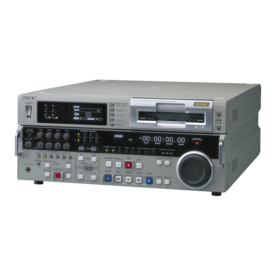
- Page 1 3-869-570-12(1) Digital Videocassette Recorder Operating Instructions Before operating the unit, please read this manual thoroughly and retain it for future reference. DSR-2000A/2000AP 2005 Sony Corporation...
-
Page 2: Important Safety Instructions
The model and serial numbers are located in the rear. expose the unit to rain or moisture. Record these numbers in the spaces provided below. Refer to them whenever you call upon your Sony dealer regarding this product. To avoid electrical shock, do not open the cabinet. - Page 3 Subpart B of Part 15 of FCC Rules. For the customers in Europe (DSR-2000AP only) This product with the CE marking complies with both the EMC Directive (89/336/EEC) and the Low Voltage Directive (73/23/EEC) issued by the Commission of the European Community.
-
Page 4: Table Of Contents
Table of Contents Table of Contents Chapter 1 Overview Features ................8 DVCAM Format ..............8 Variety of Interfaces ............... 9 Full Functionality for More Efficient Editing ......9 Other Features ..............11 Options ................. 11 System Configuration ............ 12 Location and Function of Parts ........ - Page 5 Chapter 4 Automatic Editing ............66 Editing Overview of Automatic Editing ........... 66 Button/Switch Settings for Editing ........69 Selecting an Edit Mode ............70 Setting Edit Points ..............71 Checking Edit Points ............74 Modifying Edit Points ............75 Cuing Up to Edit Points ............
- Page 6 Table of Contents Chapter 5 Adding to/Deleting From ClipLink Log Data ....101 ClipLink Operation Adding Mark IN/OUT Points ..........101 (Continued) Deleting Mark IN/OUT Points ........... 101 Automatically Creating New ClipLink Log Data ..103 Chapter 6 Setup Menu Menu System Configuration ........
- Page 7 Chapter 8 Maintenance and Condensation ..............133 Troubleshooting Head Cleaning ............... 133 Periodic Maintenance ........... 134 Troubleshooting ............135 Error Messages ..............137 Alarm Messages ..............137 Appendixes Notes on Use ..............140 Specifications ............... 141 Glossary ................ 144 Index ................147 Table of Contents...
-
Page 8: Features
DVCAM is a professional -inch digital recording format developed by Sony from the consumer DV There are two recording modes: two-channel mode component digital format (4:1:1 for DSR-2000A/4:2:0 (48-kHz sampling and 16-bit quantization), which for DSR-2000AP). -
Page 9: Variety Of Interfaces
SMPTE signals in component digital format (D1). 305M. 3) is a trademark of Sony Corporation and indicates that This unit uses SDTI to transmit DV data, and the input/ this product is in agreement with IEEE1394-1995 output connectors are labled “SDTI(QSDI)”. - Page 10 (for DSR-2000A), black level (for DSR-2000AP), and chroma phase. Internal time code generator and reader An internal timecode generator and reader enables timecode compliant with SMPTE/EBU format to be recorded and played back.
-
Page 11: Other Features
Other Features Options Menu operations for functions and RMM-131/1 Rack Mount Kit operating settings This kit can be used to mount the unit in an EIA- standard 19-inch rack. To make it easier to use this unit for any particular purpose, various functions and operating settings are provided in the menu system. -
Page 12: System Configuration
Production of some of the peripherals and related devices shown below has been discontinued. For advice about choosing devices, please contact your Sony dealer or a Sony sales representative. SDI INPUT/OUTPUT DVCAM cassette DVCAM camcorder DVW/MSW series VCR etc. -
Page 13: Location And Function Of Parts
Location and Function of Parts There are four control panels as shown in the figure below. Connector panel (See page 29.) Upper control panel (See page 14.) Lower control panel (See page 17.) Subsidiary control panel (See page 26.) To adjust the position of the lower control panel You can fix the lower control panel in any position between vertical and horizontal for ease of operation. -
Page 14: Upper Control Panel
Location and Function of Parts Upper Control Panel 1 POWER switch 2 Audio level meters 3 Cassette compartment 1 Input selection/audio mode display section (see below) 3 Remote control 2 Input selection section setting section (see page 15) (see page 16) INPUT SELECT SDTI/i.LINK POWER... - Page 15 1 INPUT display 2 Input selection section Indicates the input signal selected with the SDTI/ i.LINK button in the input selection section. V:SDTI: Digital video signal in SDTI(QSDI) format In this mode, you can select any audio input, INPUT SELECT though the video signal is recorded with a delay of 1 SDTI/i.LINK button SDTI/i.LINK...
- Page 16 Location and Function of Parts 2 VIDEO IN button 5 MIXING (mixing setting on/off) button Each press of this button cycles through the following This enables (ON) or disables (OFF) the setting for input video signal selection options. audio input mixing made with extended menu item •...
-
Page 17: Lower Control Panel
Lower Control Panel 1 METER FULL/FINE button 2 REC controls 3 PB controls 4 MONITOR SELECT buttons 1 Monitor/menu/display setting 2 Display section (see page 19) section (see page 18) MONITOR SELECT CH-1 CH-2 CH-3 CH-4 METER COUNTER SHUTTLE ClipLink FULL/FINE U-BIT TC REPEAT... - Page 18 Location and Function of Parts 4 MONITOR SELECT buttons 5 HEADPHONES jack and PHONE LEVEL There are four buttons CH-1 to CH-4 (channels 1 to 4) control in each of the upper (L) and lower (R) rows. Use these Connect stereo headphones with an impedance of 8 buttons to select the channels for audio output via the ohms to monitor the sound during recording, playback HEADPHONES connector on the lower control panel...
-
Page 19: Display Section
4 RESET button 7 HOLD button To reset a time counter value (COUNTER) shown in To stop updating of the time code or user bit value in the time counter display, press this button. the time counter display (that is, to hold the display), Resetting the COUNTER value erases all edit points. - Page 20 U-BIT: User bit data 9 SERVO indicator TC: SMPTE time code (DSR-2000A) or EBU time When the drum servo and capstan servo are locked code (DSR-2000AP) this indicator lights. 5 Time counter display !º CHANNEL CONDITION indicator Indicates the count value of the time counter, time...
- Page 21 !¡ Tape end alarm indicator 3 Edit mode setting section Starts flashing when the remaining capacity of the tape is for about 2 minutes. !™ SHUTTLE/JOG indicators 1 INSERT buttons When searching in shuttle or variable mode using the search dial, the SHUTTLE indicator lights, and when INSERT searching in jog mode using the search dial, the JOG VIDEO...
- Page 22 Location and Function of Parts 4 Editing control section 1 DELETE button LIST MARK 6 TRIM buttons TRIM 2 MEMORY indicator 7 AUDIO IN button and AUDIO OUT button AUDIO DELETE DMC EDIT ENTRY SHIFT MEMORY 3 DMC EDIT button 8 ENTRY/SHIFT button AUTO EDIT...
-
Page 23: Tape Transport Control Section
8 ENTRY/SHIFT button 1 STANDBY button Use this button for setting edit points, carrying out When a cassette is inserted and this button is off, to put ClipLink operations, and so forth. the VCR in standby mode, press the button, turning it •... - Page 24 Location and Function of Parts 4 EDIT button 6 Search control section To carry out manual editing, press this button simultaneously with the PLAY button. Monitoring in E-E mode When the unit is in stop mode, pressing this button lights it, and you can monitor the input signal selected with the ASSEMBLE button or INSERT buttons in E- E mode.
- Page 25 Playback modes using the search dial Playback Operations and functions mode Shuttle Press the SHUTTLE button or the search dial so that the SHUTTLE indicator in the display section lights, then turn the search dial. Playback is carried out at a speed determined by the position of the search dial.
-
Page 26: Subsidiary Control Panel
9 VITC switch 8 DF/NDF switch (DSR-2000A only) 7 FREE RUN/REC RUN switch 6 INT/EXT−PRESET/REGEN switch !™ SET UP (DSR-2000A)/BLACK LEVEL (DSR-2000AP) !¢ Y/C DELAY knob and PRESET/MANUAL switch knob and PRESET/MANUAL switch !£ CHROMA knob and PRESET/MANUAL switch !∞ CHROMA PHASE (HUE) (DSR-2000A)/... - Page 27 3 REC (record) INHIBIT switch Selection relating to the internal time code generator When this switch is set to ON, the REC INHIBIT Setting Operation of the internal time code generator indicator in the display section lights, and recording on PRESET The initial value of the time code produced by the internal time code generator can be preset tape is no longer possible.
- Page 28 2000A) in the range ±30 IRE , or the black level !¶ SC (subcarrier) knob (DSR-2000AP) in the range ±210 mV. This adjusts the output signal subcarrier phase with !£ CHROMA (chrominance) knob and PRESET/ respect to the input reference signal to this unit in the MANUAL switch range ±180°.
-
Page 29: Connector Panel
Connector Panel 1 Analog video input/output section (see page 30) 2 Digital input/output section (see page 31) ANALOG VIDEO I/O DIGITAL AUDIO I/O(AES/EBU) SDTI(QSDI) i.LINK INPUT OUTPUT REF.VIDEO VIDEO IN CH-1/2 CH-3/4 75Ω 75Ω SDI INPUT SDI OUTPUT CH-1/2 CH-3/4 (SUPER) LEVEL LEVEL... - Page 30 C (chroma: 3.58 MHz for DSR-2000A or 4.43 This connector outputs a reference video signal, except MHz for DSR-2000AP) components to this connector. when i.LINK is selected in the input selection section (see page 15). 6 S VIDEO OUT connector (4-pin)
- Page 31 !º VIDEO OUT 1, 2, and 3 (SUPER) connectors 8 COMPONENT VIDEO Y/R–Y/B–Y IN connectors (BNC type) (BNC type) Input analog component video signals (Y/R−Y/B−Y) These connectors output analog composite video signals. to these connectors. When the CHARACTER switch on the subsidiary 9 COMPONENT VIDEO Y/R–Y/B–Y OUT control panel is set to ON, connector 3 (SUPER) connectors (BNC type)
- Page 32 Location and Function of Parts 3 External device connectors Notes • If you monitor the output signal from this connector on another device in E-E mode while making a search at speeds in the range +1 to + or – to –1 VIDEO CONTROL times normal speed, the signal may sound differently...
- Page 33 4 AUDIO IN CH-1 (channel 1) to CH-4 connectors 4 Analog audio input/output section (XLR 3-pin, female) Use these connectors to connect separate channels of audio input from a player VCR or other external audio 1 AUDIO IN −6dBm/0dBm/+4dBm switches equipment.
-
Page 34: Usable Cassettes
Usable Cassettes This unit can use the DVCAM cassettes listed below. Notes on using cassettes Model name Size • Before storing the cassette, rewind the tape to the PDV-64*/94*/124*/184*/34* Standard size beginning and be sure to put the cassette in its storage PDVM-12*/22*/32*/40* Mini size case, preferably on end instead of flat on its side. -
Page 35: Inserting And Ejecting Cassettes
Preventing accidental erasure Set the REC/SAVE switch on the cassette to SAVE to Mini size (Insert the cassette Outer guides prevent accidental erasure of recorded contents. into the middle of the cassette compartment.) REC/SAVE switch Standard size Set to SAVE SAVE To enable re-recording Set the cassette’s REC/SAVE switch to REC. -
Page 36: Displaying Time Data And Unit's Operating Status-Superimposing Text Information
Chapter Setting/Displaying Time Data and Text Information Displaying Time Data and Unit’s Operating Status− Superimposing Text Information To display superimposed time data and text information about the operating status of the unit on the monitor, set the CHARACTER switch on the subsidiary control panel to ON. When the CHARACTER switch is set to ON, the text information is superimposed on the output of the VIDEO OUT 3 (SUPER) connector and also of the SDI OUTPUT 3 (SUPER) connector. - Page 37 6 Operating mode 5 Recorder/player selection a) This character can appear on the DSR-2000A only. The character to appear in these two columns is always a colon (:) on the DSR-2000AP. Note The example above shows the factory default configuration.
- Page 38 Displaying Time Data and Unit’s Operating Status−Superimposing Text Information 2 Time code reader drop-frame mark (for DSR-2000A only) Drop frame mode (factory default setting) Non-drop frame mode 3 Time code generator drop-frame mark (for DSR-2000A only) Drop frame mode (factory default setting) Non-drop frame mode 4 VITC field “...
- Page 39 Display Operation mode Block A Block B CASSETTE OUT Cassette is not loaded TAPE UNTHREAD Tape has not been threaded STANDBY OFF Standby off mode STOP Stop mode F.FWD Fast forward mode Rewind mode PREROLL Preroll mode PLAY Playback mode (servo unlocked) PLAY LOCK Playback mode (servo locked)
-
Page 40: Setting Time Code And User Bits
Setting Time Code and User Bits Setting an initial time code value Set the buttons and switches as shown below. REMOTE button CHARACTER switch DF/NDF switch FREE RUN/REC RUN switch INT/EXT−PRESET/REGEN switch Button/switch settings Buttons/switches Settings REMOTE button CHARACTER switch INT/EXT−PRESET/REGEN switch INT−PRESET FREE RUN/REC RUN switch... - Page 41 Press the COUNTER SEL button and select TC. Time data type indicator TC lights in the display section of the lower control panel. Press the HOLD button. The first digit of the time counter display (hours:minutes:seconds:frames) in the display section begins to flash. To set all digits to 0 Press the RESET button.
- Page 42 Setting Time Code and User Bits To set user bits You can record up to 8 hexadecimal digits of information (date, time, event number, etc.) in the time code track. Proceed as follows. Display section Watching the time data type indicator in the display section, press the COUNTER SEL button and select U-BIT.
-
Page 43: Synchronizing The Internal Time Code Generator With An External Signal-External Lock
Synchronizing the Internal Time Code Generator With an External Signal—External Lock You can synchronize the internal time code generator to an external time code signal (TC) input to this unit. Use this method to synchronize the time code generators of a number of VCRs, or to carry out recording maintaining the synchronization between the source video and time code. - Page 44 Setting Time Code and User Bits Set switches on the subsidiary control panel as follows. TC SELECT switch: TC or VITC according as you are synchronizing to TC or VITC INT/EXT–PRESET/REGEN switch: EXT–REGEN (left position) VITC switch: ON (when recording VITC) This starts the internal time code generator running in synchronization with the external time code generator.
-
Page 45: Recording
Chapter Recording and Playback Recording This section describes video and audio recording on the unit. Preparations for Recording Button/switch settings Before beginning recording, make any necessary button/switch settings. For details of the settings of each of the buttons/switches, see the pages indicated in parenthesis. - Page 46 Recording To change the number of audio channels to be recorded Change the setting of extended menu item 818 between 2-channel (2CH) mode and 4-channel (4CH) mode. Adjusting the audio recording levels When carrying out audio recording at a reference level Leave the REC controls pressed in.
-
Page 47: Recording Time Code And User Bit Values
Recording Time Code and User Bit Values There are the following two ways of recording time code: • Setting an initial value, then recording the output of the internal time code generator • Recording the output of the internal time code generator synchronized to an external time code generator To set an initial value then record the time code Use the procedure described in the section “Setting an initial time code... -
Page 48: Recording Operation
Recording Recording Operation To record, use the following procedure. Insert a cassette. For details, see the section “Inserting a cassette” (page 35). Hold down the REC button, and press the PLAY button. Recording starts, the servo locks, and the SERVO indicator in the display section lights. -
Page 49: Playback
Playback This section describes playback of video and audio. Preparations for Playback Button/switch settings Before beginning playback, make any necessary button/switch settings. For details of the settings of each of the buttons/switches, see the pages indicated in parenthesis. MONITOR SELECT buttons (page 18) : select the audio channels to be monitored. REMOTE button (page 16) : unlit POWER switch: 1 side PB controls (page 17) :... -
Page 50: Playback Operation
Playback Playback Operation This section describes the following types of playback: • Normal playback Playback at normal (×1) speed • Playback in jog mode Variable speed playback, with the speed determined by the speed of turning the search dial • Playback in shuttle mode Variable speed playback, with the speed determined by the angular position of the search dial •... - Page 51 If you play back to the end of the tape The tape is automatically rewound, and stops. You can change the setting of extended menu item 125 so that the tape just stops without being automatically rewound when it is played back to the end.
- Page 52 Playback Playback in shuttle mode In shuttle mode, you can control the speed of playback by the angular position of the search dial. The range of playback speed is ±32 times normal speed (can be changed using menu item 102). There are detents on the search dial at the still position and at ±10 times normal speed.
- Page 53 Playback in variable mode In variable mode, you can finely control (61 steps) the speed of playback in the range of −1 to +2 times normal speed. Noiseless playback is possible in the range of ±1 times normal speed. (The variable mode playback speed range can be changed using extended menu item 119.) There are detents on the search dial at the still position and at ±1 times normal speed.
- Page 54 Playback Playback using the capstan override function You can use the capstan override function to adjust the playback speed temporarily. This function is convenient for playback phase synchronization with another VCR playing back the same program. Display section (A) Hold down the PLAY button, and turn the search dial in the desired direction to adjust the playback speed.
-
Page 55: Dynamic Motion Control (Dmc) Playback
Dynamic Motion Control (DMC) Playback Overview DMC playback allows you to vary the playback speed for a certain section of a tape, in variable mode (from −1 to +1 times normal speed), and store the varying speed in memory for later playback at the same varying speed. For example, during a live broadcast of a sporting event you can set the start and end points of highlights while recording, and then provide immediate DMC playback of those highlights. - Page 56 Playback Storing a varying playback speed in memory To store the playback speed for DMC playback, use the following procedure. MEMORY indicator Display section 3,5,7 Press the DMC EDIT button, turning it on. Either while playing back the recorded tape, or during recording, press the ENTRY/SHIFT button and each of the following buttons simultaneously, to set the start and end points.
- Page 57 Turn the search dial to vary the playback speed. While the MEMORY indicator is flashing, the speed variations are stored in memory. On passing the speed variation end point, the MEMORY indicator changes from flashing to continuously lit, and the variable speed storing ends.
- Page 58 Playback You can start DMC playback using either the REVIEW button or PREVIEW button depending on which of the above two methods you use. REVIEW button PREVIEW button To start playback at the on-air cue from the on-air start point Use the following procedure.
-
Page 59: Synchronous Playback
Synchronous Playback Connecting two DSR-2000A/2000AP units and synchronizing their tape transport, you can carry out two-unit synchronous playback with an accuracy of ±0 frame. For equipment/signal connections and basic settings, see the section “Connections for Two-Unit Synchronous Playback” (page 131). Use the following procedure. - Page 60 Playback Hold down the ENTRY/SHIFT button, and press the PREVIEW button. Both the recorder and player start preroll followed by synchronous playback by the two units. When setup menu item 004 is set to ON and 305 set to ACCUR on the recorder side, the recorder and player tape transports are synchronized during the preroll allowing two-unit synchronous playback with ±0 frame accuracy to start at the player and recorder IN points.
-
Page 61: Digitally Dubbing Signals In Dvcam Format
Digitally Dubbing Signals in DVCAM Format In addition to straightforward tape dubbing, you can also use this unit to digitally dub signals in DVCAM format automatically from the beginning of the tape to the end, through an i.LINK or SDTI(QSDI) interface. When a tape recorded on a DSR-1/1P Digital Videocassette Recorder or DSR-300/300P Digital Camcorder is dubbed, the ClipLink log data held in the cassette memory is also copied. - Page 62 Digitally Dubbing Signals in DVCAM Format SYSTEM MENU SETUP MENU AUTO FUNCTION HOURS METER Using the search dial, select AUTO FUNCTION, then press the SET button. AUTO FUNCTION MENU SDTI DUBBING i.LINK DUBBING Using the search dial in jog mode, select either SDTI DUBBING or i.LINK DUBBING, then press the SET button.
- Page 63 Using the search dial, select a desired group of items for dubbing, then press the SET button. The menu screen changes as follows. (Example: The screen displayed when A/V/TC/CM is selected.) SDTI DUBBING (A/V/TC/CM) INSERT RECORD TAPE IN THIS VTR AND SOURCE TAPE IN THE PLAYER VTR.
- Page 64 Digitally Dubbing Signals in DVCAM Format Press the SET button. The recording tape and source tape are both automatically wound back to the beginning, and dubbing starts. At the same time, the screen changes as follows. SDTI DUBBING (A/V/TC/CM) EXECUTING. TCR 00:00:00:00 UBR 00:00:00:00 ABORT:MENU KEY...
- Page 65 If the cassette memory of the recording tape is not large enough When you insert the recording tape and source tape in this unit and the player, respectively, with A/V/TC/CM selected as the items for dubbing, their cassette memory contents are checked automatically. If, as a result, the cassette memory capacity of the recording tape is found inadequate, the following message appears.
-
Page 66: Automatic Editing
Chapter Editing Automatic Editing This section describes how to carry out automatic editing with this unit and another VCR connected to the REMOTE-IN or REMOTE-OUT connector. Overview of Automatic Editing With this unit, you can use the following two edit modes. •... - Page 67 Insert edit mode In insert editing, you insert video, audio, and time code at desired positions on an already recorded tape. You can insert all three types of data at the same time or insert one of the types separately. Note Before you use an unrecorded tape in insert editing, a video signal, e.g.
-
Page 68: Sequence Of Editing Operations
Automatic Editing Sequence of editing operations The following flowchart outlines the sequence of operations in automatic editing with two DSR-2000A/2000AP units. Sequence of Operation “Button/Switch Settings for Editing” (page 69) Making necessary settings “Usable Cassettes” (page Insert cassettes. • Insert a cassette for recording the results of editing in the recorder. -
Page 69: Button/Switch Settings For Editing
Notes on video output to the monitor In E-E mode, the video output of the unit is delayed by the time for video circuit processing with respect to the input video signal (8H). Unlike the playback operations described in Chapter 3, for playback to be carried out in edit mode with both the player and recorder specified, you can use extended menu item 701 to delay the V-SYNC phase by 8H. -
Page 70: Selecting An Edit Mode
Automatic Editing Player settings REMOTE button (page 16) : lit POWER switch: I side 9PIN (when using REMOTE- IN/-OUT) or i.LINK (when using i.LINK) button: lit PB controls (page 17) : adjust the audio playback COUNTER SEL button (page levels. 19): select the data to be displayed (counter value or time code value) -
Page 71: Setting Edit Points
Setting Edit Points Of the four edit points (recorder IN and OUT points, and player IN and OUT points) required, set any three. The last edit point is set automatically. In insert mode, you can set the edit points for video and audio separately (split editing). - Page 72 Automatic Editing Note In the following cases, the DELETE button begins to flash and you cannot carry out automatic editing. • The OUT point is before the IN point. • All four of the recorder IN and OUT points and the player IN and OUT points have been set.
- Page 73 Repeat steps 2 through 4 to set the required edit points. As each edit point is set, the corresponding button changes from flashing to continuously lit. Note During split editing, if you set six or more edit points for the recorder and player, the DELETE button starts to flash, to indicate that editing cannot be executed.
-
Page 74: Checking Edit Points
Automatic Editing When the audio IN point is not set for insert editing of audio only As long as the audio OUT point is set, the VCR is ready for preview or editing. If the audio IN point has not been set, the current tape position is automatically used as the audio IN point. -
Page 75: Modifying Edit Points
To display the duration between two edit points Press the RECORDER button or PLAYER button to select the VCR on which you wish to check the duration. The button you have pressed lights. Hold down any two of the four edit point buttons (recorder or player IN, OUT, audio IN, and audio OUT points). - Page 76 Automatic Editing To modify an edit point Use the following procedure. Display section Press the RECORDER button or PLAYER button to select the VCR on which you wish to modify the edit point. The button you have pressed lights. Hold down the IN, OUT, AUDIO IN, or AUDIO OUT button corresponding to the edit point you wish to modify, and press the TRIM buttons (+ or –).
-
Page 77: Cuing Up To Edit Points
Press the RECORDER button or PLAYER button to select the VCR on which you wish to delete the edit point. The button you have pressed lights. Hold down the DELETE button and press the IN, OUT, AUDIO IN, or AUDIO OUT button according to the edit point you wish to delete. The edit point is deleted, and the DELETE button goes off. - Page 78 Automatic Editing To preroll Use the following procedure. Press the RECORDER button or PLAYER button to select the VCR on which you wish to carry out a preroll. The button you have pressed lights. Press the PREROLL button. The tape is wound back to a position 5 seconds (factory default setting) before the edit IN point, and stops.
-
Page 79: Checking Edit Results-Preview
Checking Edit Results—Preview When you have set the edit points, the PREVIEW button flashes, indicating that you can carry out a preview. PREVIEW button To carry out a preview, press the PREVIEW button. The PREVIEW button changes from flashing to continuously lit, and the preview is carried out. -
Page 80: Executing Automatic Editing
Automatic Editing Monitor output during a preview During a preview, you can monitor the following video and audio on a monitor connected to the recorder. • From the preroll point to the IN point, you can monitor the playback from the recorder. - Page 81 Monitor output during an edit During execution of an automatic edit, on a monitor connected to the recorder, you can monitor the same video and audio as during a preview (see page 80). However, during preread editing (see page 86), only the playback from the recorder can be monitored.
- Page 82 Automatic Editing To change the OUT point after starting automatic editing operation After starting the automatic editing operation, to end the operation before the preset OUT point, hold down the ENTRY/SHIFT button and press the OUT button. The position where you pressed the button becomes the OUT point, and editing ends.
-
Page 83: Dmc Editing
DMC Editing You can carry out variable speed editing, controlling the player playback speed from the recorder. Overview of DMC Editing The following figure illustrates how the tapes move on both the player and recorder during DMC editing. Postroll Preroll IN point OUT point Recorder... -
Page 84: Carrying Out Dmc Editing
DMC Editing Carrying Out DMC Editing Setting the edit points and player speed Use the following procedure. Display section 1,7,10 MEMORY indicator Press the RECORDER button. Press the ASSEMBLE button or INSERT button to select an edit mode. Press the DMC EDIT button. The unit switches to the DMC edit mode, and the DMC EDIT button lights. - Page 85 Press the PREVIEW button. The tape is prerolled and then the recorder starts operating at normal speed and the player at the set initial speed. On passing the IN point, the MEMORY indicator begins to flash: turn the search dial to vary the playback speed. While the MEMORY indicator is flashing, the speed variations are stored in memory.
-
Page 86: Preread Editing
Preread Editing Video and audio signals already recorded on the recorder tape can be used as an edit source for insert editing. This type of editing is called “preread editing”, as the VCR uses the preread heads to read the signals in advance from the tape. - Page 87 Notes • You cannot carry out preread editing using SDTI or i.LINK signals. • When the preread mode is selected (the PREREAD button is lit), to prevent feedback in the loop connection, no E-E video/audio out is available, regardless of the operating mode of the unit. When preread mode is turned off after preread editing, however, if the same channel remains connected to both input and output, an E-E signal is output, and feedback will occur.
-
Page 88: Special Editing Methods
Special Editing Methods This section describes the following editing methods. • Quick editing After selecting an edit mode, you can save on editing time by setting the edit points and previewing (or executing) the edit at the same time. • Continuous editing When you execute multiple edits in succession, you can edit from the second time on by setting the player IN and OUT points only. -
Page 89: Quick Editing
Quick Editing After selecting an edit mode, you can save on editing time by setting the edit points and previewing (or executing) the edit at the same time. Press the PLAYER button, turning it on. Stop the tape on the player at the position you wish to make the IN point. -
Page 90: Continuous Editing
Special Editing Methods Press the AUTO EDIT button. The edit starts. When the edit finishes, the recorder stops at the OUT point and the player stops about 2 seconds after the OUT point. To edit even more quickly By skipping the preview in the foregoing procedure, you can execute the edit even more quickly. - Page 91 To carry out continuous editing, use the following procedure. Press the PLAYER button, turning it on. Set the player IN and OUT points. For details of how to set IN and OUT points, see the section “Setting Edit Points” (page 71). On the recorder, the OUT point for the previous edit becomes the new IN point.
-
Page 92: Standalone Editing
Special Editing Methods Standalone Editing This method allows you to use as the player an external device which cannot be controlled remotely through the REMOTE-IN or REMOTE- OUT connector. For example, you can record a color bar signal from a signal generator in the joints between the scenes of an already completed tape. -
Page 93: Manual Editing
Manual Editing To carry out manual editing, start playback on the player beforehand, then use the following procedure. 4,6 1 Press the RECORDER button, turning it on. Use the search dial in jog or shuttle mode to find the edit start point (the recorder IN point), and stop the tape just before this point. -
Page 94: Adding A Narration (Sound-On-Sound)
Special Editing Methods Adding a Narration (Sound-on-Sound) By means of preread editing with an audio mixer connected (see page 86), you can mix in an audio signal with the existing recorded soundtrack, but extension menu item 819 provides a simple sound-on-sound editing function for adding a narration, using this unit alone. -
Page 95: Cliplink Operation
Chapter ClipLink Operation Overview of ClipLink Operation The ClipLink function provides the following. Notes • Displaying ClipLink log data • For a tape on which index pictures are already • Cueing up to Mark IN/OUT points and cue points recorded, you cannot change any ClipLink log data •... -
Page 96: Displaying Cliplink Log Data
Displaying ClipLink Log Data To display ClipLink log data, hold down the ENTRY/ Detailed Data Display SHIFT button and press the LIST/– button. To check more details related to the data item selected on the ClipLink log data list, proceed as follows. LIST/–... -
Page 97: Cuing Up To Mark In/Out And Cue Points
Cuing Up to Mark IN/OUT and Cue Points Cuing Up to Any Desired Cuing Up to Adjacent Mark IN/ Position Cue Points To cue up to the point specified by the data item Once you select data on a ClipLink log data list, you selected on the ClipLink log data list, proceed as can cue up to the point preceding or following the follows. -
Page 98: Rewriting Cliplink Log Data
Rewriting ClipLink Log Data You can rewrite the reel number, Mark IN/OUT points Repeat steps 3 and 4 until the settings for all digits and OK/NG status included in the ClipLink log data. are complete. When all digits have been set, hold down the ENTRY/SHIFT button and press the MARK/+ Changing the Reel Number button. -
Page 99: Changing The Ok/Ng Status
Using the search dial, move the selection mark Changing the OK/NG Status (asterisk) to the desired data item on the ClipLink log data list. To change the OK/NG status of the data item selected on the ClipLink log data list, proceed as follows. The Mark IN point address is stored as the IN point and the Mark OUT point address is stored as the OUT point. - Page 100 Rewriting ClipLink Log Data Hold down the STOP button and press the SET button. This returns to the original ClipLink log data list. Note If you carry out step 5 skipping step 4, the original ClipLink log data list appears again on the monitor and, in this case, the OK/NG status is not rewritten.
-
Page 101: Adding To/Deleting From Cliplink Log Data
Adding to/Deleting From ClipLink Log Data You can add new Mark IN/OUT point data to the Holding down the ENTRY/SHIFT button, press ClipLink log data or delete Mark IN/OUT point data the MARK/+ button. from the ClipLink log data. The ENTRY/SHIFT button goes out, and the Mark IN point and Mark OUT point data is added to the end of the existing ClipLink log data. - Page 102 Adding to/Deleting From ClipLink Log Data Holding down the DELETE button, press the MARK/+ button. The specified data disappears from the ClipLink log data list. Holding down the ENTRY/SHIFT button, press the MARK/+ button. Note If you exit from the ClipLink log data list skipping step 3, the previous data is restored.
-
Page 103: Automatically Creating New Cliplink Log Data
Automatically Creating New ClipLink Log Data When the setup menu item 129 (CLIPLINK) is set to To erase ClipLink log data After displaying the ClipLink log data list, proceed as ON, you can automatically create new Mark IN/OUT follows. points during recording or editing operation. For information about how to operate the setup menu, see Chapter 6 “Setup Menu”... - Page 104 Automatically Creating New ClipLink Log Data Cue point time codes How to record ClipLink log data This type of data is especially useful when shooting scenes that may contain unexpected events, such as The following describes how to record the various when shooting for sports coverage or documentaries.
-
Page 105: Menu System Configuration
Chapter Setup Menu Menu System Configuration For detailed information about menu operation relating to The setup menu system of this unit comprises the basic the digital hours meter, see “Digital hours meter” (page menu and extended menu. 134). • Basic menu This menu is used to make settings relating, for •... - Page 106 VIDEO OUT 3 (SUPER) connector and SDI OUTPUT 3 (SUPER) connector for superimposed display on the monitor. 00... 0A ...2A (DSR-2000A) /00... 09 ...29 (DSR-2000AP): The hexadecimal value 00 is for the far left of the screen. Increasing the value moves the position of the characters to the right.
- Page 107 Items in the basic menu (continued) Item number Item name Settings CHARACTER Determine the vertical size of characters such as time code output from the VIDEO OUT V-SIZE 3 (SUPER) connector and SDI OUTPUT 3 (SUPER) connector for superimposed display on the monitor. ×1 : Standard size ×2: 2 times standard size MENU DISPLAY...
-
Page 108: Basic Menu Operations
Basic Menu To display the item group name Basic Menu Operations Items in the menu are arranged in groups, by the 100's digit of the item number. To display the name of the This section describes the basic menu display and how group to which the currently selected item belongs, to change the settings. - Page 109 The setting value changes at a rate depending on Changing the currently displayed menu the search dial position (when the SHUTTLE item indicator is lit) or on the search dial rotation rate (when the JOG indicator is lit). Search dial SHUTTLE/JOG indicator SHUTTLE Setting value (flashes while changing)
- Page 110 Basic Menu Menu bank operations (menu items B01 to B14) This unit allows four different complete sets of menu settings to be saved in what are termed "menu banks" numbered 1 to 4. Saved sets of menu settings can be recalled for use as required.
-
Page 111: Extended Menu
Extended Menu Items in the Extended Menu The extended menu contains the following items. In the Settings column of the table, the factory default settings are indicated by an enclosing box. Menu items in the 100s, relating to the control panels Item number Item name Settings... - Page 112 Extended Menu Menu items in the 100s, relating to the control panels (continued) Item number Item name Settings JOG DIAL Select the tape speed characteristics for the search dial rotation rate in jog mode. RESPONSE TYPE1 : Tape speed varies linearly over the range –1 to +1. TYPE2: Tape speed varies stepwise as shown in the figure below over the range –3 to +3.
- Page 113 Menu items in the 100s, relating to the control panels (continued) Item number Item name Settings CLIPLINK Select whether to create ClipLink log data. OFF : Do not create. ON: Create. When recording, the recording starting point is made a Mark IN point and the recording ending point is made a Mark OUT point.
- Page 114 Extended Menu Menu items in the 300s, relating to editing operations (continued) Item number Item name Settings AUTO-DELETION Select what happens when an erroneous edit point is set. MANU : A warning is given by flashing the DELETE button on the lower control panel. INCONSISTENT The operator must manually delete the unnecessary edit point .
- Page 115 Menu items in the 300s, relating to editing operations (continued) Item number Item name Settings EDIT RETRY When editing with two DSR-2000A/2000AP units, select the operation if the recorder was not synchronized in time. (Make this setting on the recorder.) OFF: Editing is not carried out, and the unit stops.
- Page 116 You can insert the VITC signal in two places. To insert it in two places, set both items 601 and 602. For DSR-2000AP Select a line to insert the VITC in. 9H ... 19H ... 22H: Select any line from 9 to 22.
- Page 117 Menu items in the 600s, relating to the time code generator Item number Item name Settings TCG REGEN Select the signal to be regenerated when the time code generator is in the regeneration MODE mode (i.e., when the PRESET/REGEN switch on the subsidiary control panel is set to REGEN, or the unit is in automatic edit mode).
- Page 118 Select the test signal to be output from the internal test signal generator. INTERNAL VIDEO SIGNAL CB100 (DSR-2000AP only): 100% color bar signal GENERATOR CB75: 75% color bar signal BB: Black burst signal Default setting: CB100 (for DSR-2000AP)/CB75 (for DSR-2000A) VIDEO SETUP Select whether to remove the setup (7.5%) from the input analog video signals and...
- Page 119 Item name Settings Switching blanking on or off for the 335th line of the input video signal. Select the INPUT VIDEO reference video signal to use. BLANK (DSR-2000AP only) Sub-item THROUGH : Do not mute. LINE335 BLANK: Mute. CLOSED Select whether to mute the closed caption signal to be superimposed on the 1st and CAPTION BLANK 2nd fields of the output video signal.
- Page 120 Select the audio reference level (headroom) for recording on tape. REFERENCE –12dB LEVEL –16dB –18dB (factory default for DSR-2000AP) –20dB (factory default for DSR-2000A) AUDIO OUTPUT Select the analog audio output reference level. LEVEL +4dB : Set the analog output level of the signal at the reference level to +4 dBm.
-
Page 121: Extended Menu Operations
Making settings for mixing an audio input Extended Menu Operations signal (extension menu item 819) To use the extended menu, set basic menu item 099 Using extension menu item 819, you can mix audio MENU GRADE to ENHAN beforehand. input signals, dub an audio input signal over a channel previously recorded on the tape, or mix an audio input In the extended menu, you can carry out the same signal with an audio channel recorded on the tape... - Page 122 Extended Menu Monitor screen To enable the setting of extension menu item Press the MIXING button in the upper control panel, Recording channel numbers turning it on. When the MIXING button is off, the settings of ITEM-819 extension menu item 819 are ignored, and the input AUDIO INPUT SOURCE channels and recording channels are recorded one-to- ARRANGE...
-
Page 123: Reference Video Signals For Analog Signal Editing
Production of some of the peripherals and related devices described in this chapter has been discontinued. For advice about choosing devices, please contact your Sony dealer or a Sony sales representative. Reference Video Signals for Analog Signal Editing In order to provide stable video and audio signals for analog editing, it is necessary to input a reference REF. -
Page 124: Connections For Cut Editing Using I.link Interface
Connections for Cut Editing Using i.LINK Interface Connections for Cut Editing Using i.LINK Interface By interconnecting two DSR-2000A/2000AP units Note with an i.LINK cable (DV cable) and using the one as When you edit using the i.LINK connector, with video a player and the other as a recorder, you can configure and audio signal input set to “i.LINK”... -
Page 125: Connections For A Digital Nonlinear Editing System
Connections for a Digital Nonlinear Editing System This unit can be connected to a nonlinear editor Notes supporting DV/DVCAM with an i.LINK cable (DV • Refer to the documentation of your nonlinear editing cable). Shown below is an example of connections to equipment and software for more information about use this unit as a recorder in a nonlinear editing connection and settings on the nonlinear editing... -
Page 126: Connections For Digital Nonlinear Editing Using Sdti (Qsdi) Interface
Connections for Digital Nonlinear Editing Using SDTI (QSDI) Interface This unit can be connected to an ES-7 EditStation to The following is a connection diagram for digital non- configure a digital non-linear editing system. Using the linear editing system in which this unit serves as the SDTI (QSDI) interface, you can transfer video, audio, recorder. -
Page 127: Connections For Cut Editing Using Sdi Interface
Connections for Cut Editing Using SDI Interface The following figure shows an example of connections for a cut editing system using this unit together with an MSW-2000/2000P VCR using an SDI connection. In this example, the MSW-2000/2000P is used as the recorder and this unit is used as the player. -
Page 128: Connections For Preread Editing
Connections for Preread Editing The following figure shows an example of connections Note for a preread editing system using two DSR-2000A/ As the video switcher and the audio mixer, use devices 2000AP units together with a video switcher, audio with low I/O delay or devices that support the preread mixer and editing control unit. -
Page 129: Settings Required When Connecting An External Editing Control Unit
1 2 3 4 5 6 7 8 9 10 11 12 13 14 15 • SW3 Setting 80 14 00 96 05 05 03 80 0A 08 FE 00 80 5A FF Switch No. • When using the DSR-2000AP (PAL) Setting OFF OFF OFF ON —... -
Page 130: Connections For Component Analog Recording
Connections for Component Analog Recording The following shows connections for a system in which analog playback signals from another recorder or player are recorded on the DSR-2000A/2000AP. In this system, the video signals are analog component signals and the audio signals are recorded from audio channels 1 and 2. -
Page 131: Connections For Two-Unit Synchronous Playback
Connections for Two-Unit Synchronous Playback The following shows connections for synchronous For information about how to carry out two-unit synchronous playback, see the section “Synchronous playback using two DSR-2000A/2000AP units. Playback” on page 59. In the following, the controlling unit is referred to as the recorder and the controlled unit as the player. -
Page 132: Connections For Digitally Dubbing Signals In Dvcam Format
Connections for Digitally Dubbing Signals in DVCAM Format You can use this unit to digitally dub signals in Connecting two DSR-2000A/2000AP units using the i.LINK interface DVCAM format automatically from the beginning of Make the same connections and settings as described the tape to the end, through an i.LINK or SDTI(QSDI) in the section “Connections for Cut Editing Using interface. -
Page 133: Condensation
Chapter Maintenance and Troubleshooting Condensation If condensation occurs while the unit is If you move the unit suddenly from a cold to warm operating: location, or if you use it in a very humid place, The alarm message “MOISTURE HAS BEEN moisture from the air may condense on the head drum. -
Page 134: Periodic Maintenance
COUNTER SEL button Use the information as a guide in scheduling periodic maintenance. Display section For periodic maintenance, cousult your Sony dearler. Display modes of the digital hours meter H01: OPERATION mode Displays the total number of hours the unit has been powered on in units of 1 hour. -
Page 135: Troubleshooting
Troubleshooting If an alarm message appears in the display section or unit appears to be malfunctioning, please check the on the video monitor connected to this unit, or if the following before contacting your Sony dealer. Operation problems Symptom Cause Remedy The unit’s control buttons do... - Page 136 Troubleshooting Input problems Symptom Cause Remedy It is not possible to record an No SDTI signal is input to the unit. Connect an SDTI (QSDI) signal to the SDTI SDTI signal. (QSDI) INPUT connector. a) In this state, an alarm message appears in the display section and on the monitor screen.
-
Page 137: Error Messages
Error Messages This unit is provided with a self-diagnostic function Note that detects internal abnormalities. When it detects an To display error messages on the monitor screen, set abnormality, it outputs an error message to the monitor the CHARACTER switch on the subsidiary control connected to the unit and indicates an error code in the panel to ON. - Page 138 REF NON-STD REF. VIDEO. Abnormal settings selected in setup menu. Correct the setup menu settings. Contact your ILL. SETUP Sony dealer if this alarm message appears again after making corrections. Audio mixing mode cannot be changed — REC mode! during recording.
- Page 139 Alarm messages and associated directions (Continued) Alarm message on monitor screen Direction Alarm message in the display section Cause Remote mode is selected. Turn off the REMOTE button. REMOTE! Tape cannot be replayed. Use a tape recorded in 525/60 format. (For DSR- 625/50 Tape (For DSR- 2000A) 2000A)
-
Page 140: Notes On Use
Appendixes Notes on Use Avoid violent impacts Operation and storage locations Dropping the unit, or otherwise imparting a violent Avoid operation or storage in any of the following shock to it, is likely to cause it to malfunction. places. • Location subject to extremes of temperature Do not obstruct ventilation openings (operating temperature range 5°C to 40°C (41°F to To prevent the unit from overheating, do not obstruct... -
Page 141: Specifications
Specifications General Tape transport control system Power requirements Tape speed 28.193 mm/s (DSR-2000A) 100 to 240 VAC, 50/60 Hz 28.221 mm/s (DSR-2000AP) Power consumption Recording/playback time 120 W Using PDV-184ME standard-size Peak inrush current cassette: 184 minutes or less (1) Power ON, current probe method: 65A (240V) - Page 142 REF. VIDEO IN BNC type ×2 (loop-through), black VIDEO OUT 1, 2, 3 (SUPER) BNC type ×3, composite, 1.0 Vp-p, burst, 0.286 Vp-p (DSR-2000A) or 75 Ω, sync negative 0.3 Vp-p (DSR-2000AP), 75 Ω, REF. VIDEO OUT sync negative BNC type ×1, composite sync, DIN 4-pin ×1 S VIDEO IN Y: 1.0 Vp-p, 75 Ω, sync negative...
- Page 143 D-sub 9-pin, female, for connection Y: 1.0 Vp-p, 75 Ω, sync negative of another DSR-2000A/2000AP C: 0.286 Vp-p (DSR-2000A) or unit or other editing controller, 0.3 Vp-p (DSR-2000AP), 75 Ω complying with RS-422A (burst level) REMOTE-OUT D-sub 9-pin, female, for loop- COMPONENT VIDEO OUT Y/R–Y/B–Y...
-
Page 144: Glossary
Glossary Glossary AES/EBU format Drum Loading A unified format for digital audio signals. See “Head drum”. Also called “threading”. To pull the tape It allows a single XLR connector to carry out of the cassette case, thread it along the the signals for two channels. - Page 145 R–Y signal SMPTE Tape tension One of the color difference signals, the R Abbreviation of Society of Motion Picture The tension applied to a tape. For the tape (red) signal minus Y (luminance) signal. and Television Engineers, a professional to run properly while being wound on the association established in the USA.
- Page 146 Glossary User bits These are also referred to as “user’s bits”. The user bits are a 32-bit segment of the timecode recording area. The user can select what to record in this segment and how to use the recorded data. For example, it can be used to record date information in addition to the timecode data or ID numbers for tape reels or...
-
Page 147: Index
Index ClipLink log data DIGITAL AUDIO (AES/EBU) adding to/deleting from 101 IN connectors 31 creating 103 OUT connectors 32 AC IN connector 29 display 96 Digitally dubbing DVCAM signals 61 Adding a narration 94 recording 104 connections 132 Alarm messages 137 rewriting 98 Display section 19 Analog... - Page 148 Index External device connectors 32 jog mode playback 51 normal playback 50 External editor settings 128 shuttle mode playback 52 Lower control panel 17 External lock 44 synchronous playback 59 position adjustment 13 variable mode playback 53 PLAYER button 18 POWER switch 14 F FWD button 24 Preread...
- Page 149 W, X S VIDEO Tape end alarm indicator 21 Wide screen 11 IN connector 30 Tape transport control section 23 OUT connector 30 TC SELECT switch 27 Y, Z SC knob 28 Text information 36 Y/C DELAY knob 28 Time code cut editing 127 generator/reader 10, 43 INPUT connectors 32...
- Page 150 Sony Corporation...