Sony DSR-2000A Service Manual
Digital videocassette recorder
Hide thumbs
Also See for DSR-2000A:
- Operating instructions manual (150 pages) ,
- Brochure (28 pages) ,
- Brochure (10 pages)

Related Manuals for Sony DSR-2000A


Summary of Contents for Sony DSR-2000A
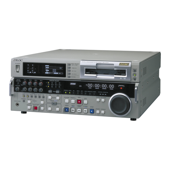
- Page 1 DIGITAL VIDEOCASSETTE RECORDER DSR-2000A DSR-2000AP HD UP-CONVERTER BOARD DSBK-2020 SERVICE MANUAL Volume 1 1st Edition (Revised 1)
- Page 2 Ce manual est destiné uniquement aux personnes compétentes en charge de l’entretien. Afin de réduire les risques de décharge électrique, d’incendie ou de blessure n’effectuer que les réparations indiquées dans le mode d’emploi à moins d’être qualifié pour en effectuer d’autres. Pour toute réparation faire appel à une personne compétente uniquement. DSR-2000A/2000AP...
- Page 3 Hävitä käytetty paristo valmistajan ohjeiden constructeur. mukaisesti. Mettre au rebut les batteries usagées conformément aux instructions du fabricant. ADVARSEL! Lithiumbatteri-Eksplosionsfare ved fejlagtig håndtering. Udskiftning må kun ske med batteri af samme fabrikat og type. Levér det brugte batteri tilbage til leverandøren. 1 (P) DSR-2000A/2000AP...
- Page 4 Klebestreifen ab oder geben Sie die Batterien einzeln in einen Plastikbeutel. Gooi de batterij niet weg. maar lever hem in als KCA. Bij dit produkt zijn batterijen geleverd. Wanneer deze leeg zijn, moet u ze niet weggooien maar inleveren als KCA. 2 (P) DSR-2000A/2000AP...
-
Page 5: Table Of Contents
Extension Board ..........3-12 5-3-5. Electrical Adjust ..........5-29 3-5-3. Removal/Reattachment of the Boards ....3-13 5-3-6. Service Support ........... 5-38 3-6. Notes on Repair Parts ........... 3-27 5-3-7. Others ..............5-40 3-6-1. Flexible Card Wire Replacement ......3-27 DSR-2000A/2000AP... - Page 6 10-3-18. REC COMPONENT B-Y Level Adjustment ..10-16 7-24. Switching Regulator Replacement ....... 7-66 10-3-17. REC COMPONENT R-Y Level Adjustment ..10-16 10-3-19. REC S VIDEO Chroma Level Adjustment ..10-17 10-4. SDI/SDTI ..............10-18 10-4-1. Free Run Adjustment ........10-18 DSR-2000A/2000AP...
-
Page 7: Manual Structure
Manual Structure Purpose of this manual This manual is the Service Manual Volume 1 for the digital videocassette recorder DSR-2000A/2000AP. This manual contains the maintenance information of this equipment, and servicing information necessary for parts replacement and adjustments. Related manuals In addition to this Service Manual Volume 1, the following manuals are provided. -
Page 8: Contents
Describes the replacement procedures and adjustment after replacement. Section 8 Tape Path Alignment Describes the adjustment procedures of tape path system. Section 9 Electrical Alignment After Replacement Boards Describes the electrical adjustments after replacement boards. Section 10 Electrical Alignment Describes the electrical adjustment of each board. DSR-2000A/2000AP... -
Page 9: Operating Instructions
..CD-ROM Operation Instructions (Supplied with this unit.) This manual is necessary for the operation of this unit. The CD-ROM includes operation instructions (English, Japanese, French, German, Italian, and Spanish) in PDF format. Part number: 3-869-792-XX DSR-2000A/2000AP... -
Page 11: Installation
Section 2 Installation Be sure to install the DSR-2000A/2000AP in location satisfying the required operational environment described below to assure the DSR-2000A/2000AP superior performance and to maintain the excellent serviceability and accessibility. 2-1. Installation Procedure Start Determination of · · · 2-2. Operational Environment ·... -
Page 12: Installation Space
(The unit can be mounted in a 19-inch standard rack) . Remote control cable : RCC-5G/10G/30G . Cleaning cassette tape : DV12CL (Standard size), DVM12CL (Mini size) . Digital video cassette (Mini size) : PDVM-12ME/22ME/32ME/40ME . Digital video cassette (Standard size) : PDV-64ME/94ME/124ME/184ME DSR-2000A/2000AP... -
Page 13: Rack Mounting
. Maximum two units can be mounted in a stack. For three L-angle Outer member units of more, keep a space for one unit between the mounted units, using a rack. The space should be 44 mm or more in height. Bracket L-angle Rack DSR-2000A/2000AP... - Page 14 L-angles. Be sure to use the screws B4 x 6 removed in step 3. Screws for L-angles are longer than ones for the side panels. Therefore, using the screws PSW4 x 16 may cause trouble in the unit. DSR-2000A/2000AP...
-
Page 15: Connectors
2-8. Connectors 2-8-1. Connectors/Cables When external cables are connected to the connector on a connector panel during maintenance, the following (or equiva- lents) must be used. Connectors on DSR-2000A/2000AP Side Connector/Cable Panel indication Designation Sony Part No. ANALOG IN BNC, MALE 1-560-069-11 REF. -
Page 16: Input/Output Signals Of The Connectors
Reference level switchable (_6/0/+4 dBu), 600 Z ON/OFF/_60 dBu switchable, balanced (High impedance) DIGITAL AUDIO (AES/EBU) : BNC x2 (conformed with AES-3id-1995) TIME CODE : BNC x1 SMPTE (NTSC)/EBU (PAL) 0.5 to 18 V p-p, 3.3 kZ, unbalanced IEEE1394 connector 6P x1 i.LINK : DSR-2000A/2000AP... - Page 17 2.2 V p-p ± 3.0 dB, 600 Z, unbalanced IEEE1394 connector 6P x1 i.LINK : Stereo phone jack x1 HEADPHONES : _∞ to _13 dBu, 8 Z, unbalanced BNC x2 HD SDI OUT (DSBK-2020) : HD serial digital interface SMPTE 292M DSR-2000A/2000AP...
- Page 18 +9 V SUPPLY +9 V CONTROL PANEL (D-sub 15 pin : FEMALE) <external view> Pin No. Signal Operating Voltage 6 5 4 13 12 UNREG +12 V UNREG +12 V UNREG +12 V KY EXT UNREG GND UNREG GND UNREG GND DSR-2000A/2000AP...
- Page 19 Y (G) RECEIVE A TRANSMIT A C (G) TRANSMIT B RECEIVE B Y (X) TRANSMIT COMMON RECEIVE COMMON C (X) PRIORITY IN PRIORITY OUT RECEIVE COMMON TRANSMIT COMMON RECEIVE B TRANSMIT B TRANSMIT A RECEIVE A FRAME GROUND FRAME GROUND DSR-2000A/2000AP...
-
Page 20: Installation Setup And Adjustment
(3) The setting of audio input level select switch : + 4 dBm : +4 dBu reference level on output side 0 dBm : 0 dBu reference level on output side _ 6 dBm : _6 dBu reference level on output side 2-10 DSR-2000A/2000AP... -
Page 21: Front Panel Setting
Adjusts the amount of the Y/C delay. (15)CHROMA PHASE : Adjusts the chroma phase (the relative phase with the burst signal). (16)SYNC : Adjusts the sync phase of the output signal. (17)SC : Adjusts the phase of the subcarrier. DSR-2000A/2000AP 2-11... -
Page 22: On-Board Switch Setting
S101-3 Use this switch when operating the machine with cassette compartment removed. S101-4 This defeats an error detection of mechanism and setvo system alignment. S101-5 factory use S101-6 factory use S101-7 factory use S101-8 factory use 2-12 DSR-2000A/2000AP... - Page 23 Factory Setting S101 Push this switch when resetting the system control. — S201-1 factory use S201-2 factory use S201-3 factory use S201-4 factory use S201-5 factory use S201-6 factory use S201-7, 8 Destination setting Destination bit-7 bit-8 — DSR-2000A/2000AP 2-13...
-
Page 24: System Adjustment After Installation
. Adjust the SCH phase of this equipment to the system SCH with [SC PHASE] control on the sub control panel. . When this unit is connected to a switcher that does not have the sync switching function, the SYNC/ BURST level adjustment is required. 2-14 DSR-2000A/2000AP... -
Page 25: Service Overview
RF REC/PB, ATF detection EX-752 Intermediate board CP-341 Video/remote interface SV-212 Servo/mechanism control SY-278A System control CN-1968A i.LINK connector board CN-2858 (DSBK-2020) HD SDI OUT, i.LINK connector board) CP-342 Audio interface HIF-34 (DSBK-2020) HD up-converter board TX-96A (DSBK-2020) HD SDI intermediate board DSR-2000A/2000AP... - Page 26 Locations of Mechanism Deck Board Name Circuit Configuration SE-521 Mode sensor/tape end sensor/loading motor FG sensor SE-538 Tension sensor CN-1863 Sensor input/output board SE-525 LED signal board SE-522 Tape top sensor/reel position sensor (Mini/M/Standard) MS-64 Servo/mechanism control DSR-2000A/2000AP...
- Page 27 Locations of Cassette Compartment Board Name Circuit Configuration CN-2021 Intermediate board between CC-84 and CC-83 CC-83 Cassette compartment mode detection/intermediate board CC-85 Cassette compartment cassette in detection CC-84 Cassette compartment cassette type detection CN-2022 Intermediate board between CC-85 and CC-84 DSR-2000A/2000AP...
-
Page 28: Location Of Main Mechanical Parts
8 Brake solenoid @- Pinch roller 9 M stop solenoid assembly @= HC roller assembly !/ T brake assembly @[ Drum assembly !- MIC assembly @] Rail assembly != MIC holder assembly @\ Cassette compartment motor assembly ![ T reel motor DSR-2000A/2000AP... -
Page 29: Location Of Sensors
Detects the top and end of a tape. 4 Condensation sensor The tension arm keeps the tension of a running tape Detects condensation occurred in DSR-2000A/ constant during recording and playing. The tension 2000AP. sensor detects the mechanical position of the tension 5 Tape top sensor arm. - Page 30 2 The sensors PH1, PH2 and PH3 detect the movement of a cassette compartment by their combina- tion. 3 The sensors PH4 and PH5 detect that a mini cassette got inserted. The sensors PH4 and PH6 detect that a M cassette got inserted. The sensors PH4 and PH7 detect that a standard cassette got inserted. DSR-2000A/2000AP...
-
Page 31: Functions Of Record Proof Hole And Record Proof Plug Of Cassette
Record proof hole Reel rotation stopper 4 3 2 1 Record proof plug Pin No. Function Equipped with built-in memory Not equipped with built-in memory Detecting tape thickness DATA Detecting tape type (Example: ME/MP) CLOCK Detecting tape application (Example: consumer/professional) DSR-2000A/2000AP... -
Page 32: Removal/Installation Of Cabinet
Left side panel Section A B4 x 6 Front panel Claws Claw PWH3 x 6 B4 x 6 Claw B4 x 6 Right side panel PWH3 x 6 Foot Claw Hole B3 x 6 Bottom panel B3 x 6 DSR-2000A/2000AP... - Page 33 (6) While pressing the front panel against the unit, fix the front panel with the two screws. DSR-2000A/2000AP...
- Page 34 If the knob easily comes off, widen the slot on the volume shaft using a flat tip screwdriver. At angle up to 45d (10)Check that the knob’s turning range is within the double-headed arrow shown in the figure by turning the nine knobs clockwise and counterclockwise. 3-10 DSR-2000A/2000AP...
-
Page 35: Removal/Reattachment Of The Cassette Compartment
(CN1) of the CC-83 board. direction. (4) Reattach the top panel. (Refer to Section 3-3.) Fixing screw Cassette compartment retainer assembly (with stopper) Fixing screws (with stopper) Connector Cassette compartment (CN1) CC-83 board Flexible card wire Hook Positioning Positioning pins Positioning pin 3-11 DSR-2000A/2000AP... -
Page 36: Removal/Reattachment Of The Boards
Attach the extension board to this unit and attach the board to be checked and adjusted to the top of the extension board. Extension board Card boards which can be connected DJ-493 APR-45, DPR-136A, SV-212, (Part No.: J-6444-930-A) SY-278A, VPR-62A 3-12 DSR-2000A/2000AP... -
Page 37: Removal/Reattachment Of The Boards
(4) Reattach the CN-1968A board in the reverse order of the removing steps (1) to (3). Screws B3 x 6 Harness CN-1968A board Connctor panel Screws B3 x 6 Connectors Screw (MB-859 board) Screw B2 x 5 B2 x 5 Screw Option cover B3 x 6 3-13 DSR-2000A/2000AP... - Page 38 (10)Fix the rear panel with the unit with the five screws. CP-341 board Connctor panel Screws B3 x 6 Connectors (MB-859 board) CN605 CN604 Screw CN603 BVTP3 x 10 CN602 Screws CN601 BVTP3 x 10 Screws for connector Screws CN608 BVTP3 x 10 CN607 CN606 CP-342 board 3-14 DSR-2000A/2000AP...
- Page 39 (9) Fix the rear panel with the unit using the five screws. Rear panel CP-342 board DY-22 board Screw CN605 3 x 6 CN604 CN603 CN606 CN602 Protrusions CN601 CN607 Screw CN720 Screws PWH3 x 6 CN608 CP-341 board BVTP3 x 10 3-15 DSR-2000A/2000AP...
- Page 40 Removal/Reattachment of the RP-111 board.) Screws B3 x 6 RP shield Positioning holes Screws Screw B3 x 6 PWH3 x 6 Flexible card wire Control frame assembly Hinge lever Screw EX-752 board PWH3 x 6 CN300 Protrusions Slot CN300 (MB-859 board) 3-16 DSR-2000A/2000AP...
- Page 41 . When connecting the flexible card wire to the connector (CN710) on the KY-452 board, attach the ferrite core as following figure. Control frame assembly HP-99 board Flexible card wire Harness Claw Portion A KY cover CN710 Claw KY cover Screw Ferrite core PWH3 x 6 3-17 DSR-2000A/2000AP...
- Page 42 Control frame assembly CN713 Flexible Flexible card wire CN712 card wires CN714 Claw Portion A CN711 KY cover CN710 Screw PS3 x 6 Ferrite core KY-452 board Claw Screws KY cover PWH3 x 6 Screw PWH3 x 6 3-18 DSR-2000A/2000AP...
- Page 43 Flexible CN606 card wires CN607 CN608 CN701 CN601 CN702 CN602 CN603 CN703 CN604 CN704 CN605 Screws PWH3 x 6 CN901 CN500 Screws Screws MB-859 board PWH3 x 6 PWH3 x 6 CN505 CN503 CN502 CN501 CN902 CN504 3-19 DSR-2000A/2000AP...
- Page 44 (CN1, CN2, CN3 and CN4) of the RP-111 board. (6) Disconnect the five flexible card wires from the connectors (CN500, CN501, CN502, CN503 and CN504) of the MS-64 board. Positioning hole CN504 CN502 RP-111 board MS-64 board Positioning pin Positioning pin CN501 CN503 CN500 3-20 DSR-2000A/2000AP...
- Page 45 B2 x 4 Screw B2 x 4 Screws RP-111 board B2 x 4 CN301 CN10 Screws CN302 PWH3 x 6 CN11 Screws PWH3 x 6 Positionin Positioning hole Positioning pin CN19 CN12 CN13 Flexible card wires MS-64 board 3-21 DSR-2000A/2000AP...
- Page 46 (12)Reattach the TG1 arm assembly. (Refer to Section 7-13.) P1.4 x 3.5 SE-521 board Connector (CN4) Square holes Connector (CN3) Positionin pin Claw of worm holder Flexible card wire Square holes Flexible card wire Positionin pin Flexible card wire 3-22 DSR-2000A/2000AP...
- Page 47 (7) Reattach the SE-525 board in the reverse order of the removing steps (1) to (4). Tightening Torque : 0.1 N.m {1 kgf.cm} P1.4 x 2 Positioning hole LED holder assembly Claw SE-538 board Protrusion Claw SE-525 board Rail assembly SE-525 board 3-23 DSR-2000A/2000AP...
- Page 48 (5) Reattach the SW-11/11P board in the reverse order of the removing steps (1) to (3). Control frame assembly Notch of chassis CN701 (mother board) Screw CN702 PWH3 x 6 CN703 CN701 CN704 CN702 CN703 Notch of CN704 chassis Screw Indentation PWH3 x 6 SW-11/11P board 3-24 DSR-2000A/2000AP...
- Page 49 (CN710) on the KY-452 board, attach the ferrite core as following figure. Control frame assembly Control frame assembly Flexible card wire VR-259 board Portion A Claw Flexible card wire KY cover CN710 Ferrite core Claw KY cover Screw PWH3 x 6 3-25 DSR-2000A/2000AP...
- Page 50 (CN710) on the KY-452 board, attach the Control frame assembly ferrite core as following figure. Control frame assembly Flexible card wire VR-260 board Claw Portion A Flexible card wire KY cover CN710 Ferrite core Claw KY cover Screw PWH3 x 6 3-26 DSR-2000A/2000AP...
-
Page 51: Notes On Repair Parts
Raise the portion marked “A” of the connector and release The following six types of flexible card wire are used in the lock. Pull out the flexible card wire. the DSR-2000A/2000AP. Insertion method Take utmost care when handling the flexible card wires Insert the flexible card wire fully up to the marked line and because their life is extremely shortened by folding. - Page 52 Flexible card wire insulation side. Connect the flexible card wire after checking for the correct side as shown. If the condition side and the insulation side are connected in the wrong direction, the circuit will not operate. Locked status 3-28 DSR-2000A/2000AP...
- Page 53 Connector Connector Flexible card wire Unlocked status Flexible card wire Unlocked status Connector Connector Flexible card wire Locked status Flexible card wire Locked status 3-29 DSR-2000A/2000AP...
-
Page 54: Replacement Of Lithium Battery
Protrusion Claw SY-278A board Claw Lithium battery Time counter display block Claws ! 1-528-749-12 Sony part number : IC215 3-30 DSR-2000A/2000AP... -
Page 55: Fixtures And Tools List
Brake torque gauge (CCW) (DJ-371) Brake torque adjustment J-6443-720-A (CW) Brake torque gauge (CW) (DJ-372) Brake torque adjustment J-6444-930-A Extension board (DJ-493) Extension board for DSR-2000A J-6444-610-B Path Adjustment Board (DJ-461) For tape path adjustment RF envelope detector fixture J-6443-760-A System control/Servo... - Page 56 2 3 4 9 !/ @/ @- @= 3-32 DSR-2000A/2000AP...
-
Page 57: Upgrading The System/Servo Cpu Program Version
3-9. Upgrading the System/Servo CPU Program Version The DSR-2000A/2000AP mounts the CPU for SY and SP on the SY-278A board, CPU for SV on the SV-212 board and uses flash ROMs for stored this program. For re-writing flash ROMs, two methods are provided. -
Page 58: Version Upgrade Using The Dj-497 (In Sv Cpu)
In an event of abnormally, suspect the cause judging from status of LEDs. (5) Power down the set. And remove the fixture DJ-497. (6) Turn on the power to the set, and confirm the version in the MAINTENANCE MENU. 3-34 DSR-2000A/2000AP... -
Page 59: Version Upgrade From A Pc Through Rs-422
Operate in the order of “Select CPU.” → “ Designate hex.filename to be transferred.” → “Press Start button.”. During transferring, the status is displayed in between “PC Status” and “ Start, Cancel and Quit buttons”. The progress bar and the remaining time are displayed. 3-35 DSR-2000A/2000AP... - Page 60 After the version upgrade is completed, turn off and on the power of the VTR. (In case of upgrading the same CPU or other CPU, it is not necessary to power down.) If properly finished, confirm that CPU versions written in the MAINTENANCE MENU are correct. 3-36 DSR-2000A/2000AP...
-
Page 61: Upgrading The Fpga Program Version
3-10. Upgrading the FPGA Program Version The DSR-2000A/P mounts the FPGA (field programmable gate alley) on the process board and uses flash ROMs for loading this program. The version of data (configuration program data) these flash ROMs mounted on the board can be upgrad- ed using the following method. - Page 62 Setting of DJ-499 Board name Connect to DJ-499 PROM file name Switch setting of DJ-499 S3 APR-45 CN1700 APR-00/01 DPR-136A CN451 SIF-00/01 3-38 DSR-2000A/2000AP...
-
Page 63: Precautions For Use Of Condensation Sensor
. Do not touch the chip with bare hands. . Do not clean the chip with alcohol or other similar agents. Solders 1 pin Bracket Leads Connector Condensation sensor chip 3-39 DSR-2000A/2000AP... -
Page 65: Error Messages
MENU DATA ’ (MA I NTENANCE setting of the Setup menu is MENU) FUNCT I ON. not changed, the same alarm will appear when the main power is turned on. Display : The alarm is displayed until any key is pressed. DSR-2000A/2000AP... - Page 66 SELECT I ONS OF THE SETUP MENU’S FACTORY USE Operation after detection : None I TEMS HAVE BEEN CHANGED. Display : The alarm is displayed until SET THESE I TEMS TO any key is pressed. FACTORY PRESET VALUES. DSR-2000A/2000AP...
-
Page 67: Error Codes
OUTPUT (SUPER) connector when this unit enters the TAPE I S BE I NG EJECTED. emergency EJECT mode. WA I T UNT I L TH I S I ND I CAT I ON GOES OFF. The error code is displayed on the time counter. DSR-2000A/2000AP... - Page 68 OF FOLLOW I NG CODE : The error code is displayed on the time counter. XX-XXX Perform Section “4-3-1. How to Take Out the Cassette Whose Tape is Slacked (MANUAL EJECT) ” when a cassette tape cannot be ejected with the emergency EJECT mode. DSR-2000A/2000AP...
-
Page 69: Display Of Previously Detected Error Codes
4-2-1. Display of Previously Detected Error Codes When the DSR-2000A/2000AP detects an internal abnormality, the error code is memorized in EEPROM. (Excluding error code 9X-XXX) A maximum of 8 error codes detected previously, starting from the latest error code, can be displayed. -
Page 70: Main Codes And Sub Codes
5 : FG detected. 6 : Rotating direction error detected. 7 : Excessive tension detected. 8 : Abnormal current detected. 9 : The full top or full end of a tape cannot be released. A : Retry in progress (Unthreading and re-threading) DSR-2000A/2000AP... - Page 71 7 : Abnormality in the external serial memory-3 area 8 : Abnormality in the external serial memory-4 area 9 : Abnormality in the EEPROM area A : Abnormality in the NVRAM area B : Abnormality in the Hours Meter area F : Abnormality of MIC DSR-2000A/2000AP...
-
Page 72: Error Codes
Failed to detect the T reel FG during search. Failed to detect the S and T reel FGs during search. Detected the abnormal direction of S and T reel rotation during search. Detected slack tape during PLAY and REC. DSR-2000A/2000AP... - Page 73 Displayed until operates normally any key is after the error is pressed. solved. Failed to detect the capstan FG by the FG check during Cassette tape Displayed until the cassette tape insertion. will be ejected. next cassette is inserted. DSR-2000A/2000AP...
- Page 74 Detected the abnormal current in the cassette up/down motor. AUTO OFF EJECT Displayed until the (Emergency EJECT) next cassette is Failed to complete the cassette down motion within the inserted. specified time. Failed to complete the cassette up motion within the specified time. 4-10 DSR-2000A/2000AP...
- Page 75 Detected an abnormality of cassette compartment position sensor. Detected an abnormality of fan motor. Only error is displayed. Detected an abnormality of cassette top/end sensor LED. STOP PLAY, EJECT Detected an abnormality of tension sensor. AUTO OFF EJECT (Emergency EJECT) DSR-2000A/2000AP 4-11...
- Page 76 SPCON detected abnormality in R-TRKT. SPCON detected abnormality in R-FLTT. The servo main microprocessor detected abnormality of P-FLTD. The servo sub microprocessor detected abnormality of P-TRKD. The servo main microprocessor detected abnormality of R-FLTD. The servo sub microprocessor detected abnormality of R-TRKD. 4-12 DSR-2000A/2000AP...
- Page 77 Track pair communication error between SPCON and A1R Rear. Communication error between SPCON and AIF-INDI. Communication error between SPCON and ACTL. Communication error between SPCON and IN-DSP. Communication error between SPCON and REC-DSP. Communication error between SPCON and PB-DSP. Communication error between SPCON and OUT-DSP. DSR-2000A/2000AP 4-13...
-
Page 78: Possible Causes Of Errors
↓ When a cassette compartment is lock after it is exchanged, the trouble is caused by the cassette compartment. Otherwise the trouble is caused by cassette compartment the defective drive circuit. SV-212 board 4-14 DSR-2000A/2000AP... - Page 79 Check the pinch roller. SV-212 board, pinch solenoid against capstan. Pinch roller must be pressed against the capstan . Pinch roller has mechanical defect. shaft correctly. . Pinch solenoid is open. . Pinch solenoid drive IC is defective. DSR-2000A/2000AP 4-15...
-
Page 80: Countermeasure In An Emergency
(6) Turn the manual eject gear B (red) in the arrow Reel table (T) Skewer direction until the cassette compartment completely comes into cassette out state. Manual eject gear A (red) 4-16 DSR-2000A/2000AP... -
Page 81: Operating The Vtr Without A Cassette Tape
REV.SEARCH to five-times speed. . Never move the cleaning cloth in the vertical direction against the video head because it may break the head. . Turn the power switch off when cleaning the video head. DSR-2000A/2000AP 4-17... - Page 82 Press the [STANDBY] key on the control panel. Reel position will be changed as shown below in accor- dance with the number of pressing the [STANDBY] switch. Mini Make sure to turn off switches S101-3 and 4 on the SV-212 board after the adjustment. 4-18 DSR-2000A/2000AP...
-
Page 83: Maintenance Menu
Contents of the maintenance menu are displayed on the video monitor connected to the VIDEO OUT 3 (SUPER) connector or the SDI OUTPUT 3 (SUPER) connector and the time counter of DSR-2000A/2000AP. Values in parenthesis ( ) are time counter display. - Page 84 MEMORY DISPLAY (>MEM Check) SY MEMORY DISPLAY (>> SY MEM.) SV MEMORY DISPLAY (>> SV MEM.) SP MEMORY DISPLAY (>> SP MEM.) KY MEMORY DISPLAY (>> KY MEM.) CM DISPLAY (>> CM DISP.) DATA DISPLAY (>Data Check) SP DATA DISPLAY (>>SP DATA) DSR-2000A/2000AP...
-
Page 85: How To Operate Maintenance Menu
5-2-2. How to Enter the Maintenance Menu 1. While pressing the [DELETE] (←) key and [TRIM+] key , press the [MENU] key. The DSR-2000A/2000AP enters the maintenance menu. The maintenance menu appears on the video monitor. 2. Select the desired item using the [AUDIO|IN] (↑) key and the [IN] (↓) key. The cursor shown with a white back- ground moves to the selected item. -
Page 86: Contents Of Maintenance Menu
5. When an item is selected, press the [ENTRY] (→) key. The contents of the selected item appear. 6. Press the [DELETE] (←) key to exit MENU DATA CON- TROL and return to the main menu. 7. Press the [MENU] key to exit the maintenance menu. DSR-2000A/2000AP... - Page 87 MS-64 board. . When the SET UP MENU is upgraded by ROM’s version upgrade, an alarm message appears after the ROM is replaced. Either initialize the SET UP MENU or execute “LOAD MENU DATA” when the alarm appears. DSR-2000A/2000AP...
- Page 88 Confirm that [COMPLETE] appears and data saving is complete. In the case of trouble : Loading of the data will not start if SET UP MENU data has not been saved or the saved SET UP MENU data contains an error. DSR-2000A/2000AP...
-
Page 89: Servo Check
10. To check other menus and submenus, repeat steps 4 to 9. 11. Press the [MENU] key to exit the maintenance menu. If the [MENU] key is pressed while the check is in progress, the check operation is forcibly ended and the display returns to the main menu. DSR-2000A/2000AP... - Page 90 The respective items of “SENSOR CHECK” are described below : 1 CASS-COMPARTMENT Checks the respective switches of the cassette compartment. SW/Sensor Applicable board CC-85 CC-84 CC-84 board CC-85 board 1. Execute the CASS-COMPARTMENT. 2. Confirm that the sensors are all OFF with no cassette inserted. DSR-2000A/2000AP...
- Page 91 5. Insert the standard cassette and confirm that the status of the sensor is the monitor display shown right. 6. Insert the M-ADPT (Cassette adaptor for DVCPRO) and confirm that the status of the sensor is the monitor display shown right. * _ _ : not care DSR-2000A/2000AP...
- Page 92 [OFF] on the monitor display. In the case of trouble : If the display does not change check whether the tape-top sensor or the tape-end sensor itself is defective. Check also the tape-top/tape-end sensor circuit (MS-64, SE-521/ 522 board). 5-10 DSR-2000A/2000AP...
- Page 93 30 minutes to detect [DRY]. In the case of trouble : If the display does not change from DRY to WET!, check whether the HUMID sensor itself is defective. Check also the HUMID sensor amplifier (MS-64 board). DSR-2000A/2000AP 5-11...
- Page 94 2. Confirm the monitor display is as shown right. 3. Press the REC INHIBIT switch. Confirm that ON is displayed on the monitor display. In the case of trouble : If OFF is not displayed, check the sensor on the MIC arm. 5-12 DSR-2000A/2000AP...
- Page 95 If the brake solenoid does not emit the operating sound and the T reel motor does not rotate in the specified direction even though pressing the [AUDIO|IN] (↑) and [IN] (↓) keys, check the T reel motor assembly and reel motor driver circuit (SV-212 and MS-64). DSR-2000A/2000AP 5-13...
- Page 96 SV-212 board. Check also the MS-64 board (the driver circuit and the threading FG amplifier circuit) and the SE-512 board (the sensor). 5-14 DSR-2000A/2000AP...
- Page 97 In the case of trouble : If the monitor display does not change, check the cassette compartment motor, the SV-212 board (the sensor input circuit) and the CC-83 board (the sensor). DSR-2000A/2000AP 5-15...
- Page 98 Confirm that [REVERSE ... OK] appears on the monitor display. In the case of trouble : If the monitor display does not change, check the capstan motor and the capstan motor driver circuits (the SV-212 board, MS-64 board) 5-16 DSR-2000A/2000AP...
- Page 99 PG : [EXIST] In the case of trouble : If the monitor display does not change, check the drum motor, the SV-212 board (the drum motor driver circuit, the drum FG amp circuit and the drum PG amp circuit). DSR-2000A/2000AP 5-17...
- Page 100 If the reel table does not move or the monitor display does not change, check the reel position motor, the reel MINI/M/STD position sensor (the SE-522 and MS-64 boards) and reel position motor driver circuit (the SV-212 board). 5-18 DSR-2000A/2000AP...
- Page 101 Doing so, the monitor display returns to the main menu. In the case of trouble : If the pinch solenoid does not operate, check the pinch solenoid and the driver circuit (the SV-212 board). DSR-2000A/2000AP 5-19...
- Page 102 3. Press the [MENU] key to release the M plunger solenoid. Doing so, the monitor display returns to the main menu. In the case of trouble : If the M plunger solenoid does not operate, check the M plunger solenoid and its driver circuit (the SV-212 board). 5-20 DSR-2000A/2000AP...
-
Page 103: Servo Adjust
8. To check other menus and submenus, repeat steps 4 to 7. 9. Press the [MENU] key to exit the maintenance menu. If the [MENU] key is pressed while the adjustment is in progress, the adjustment operation is forcibly ended and the display returns to the main menu. DSR-2000A/2000AP 5-21... - Page 104 In the case of trouble : When “ADJUST INCOMPLETE” appears on the monitor display, check the SV-212 and MS-64 boards (the reel FG amplifier circuit, the reel motor driver circuit) and the S-reel motor. 5-22 DSR-2000A/2000AP...
- Page 105 Adjustment item capstan fg adjust In the case of trouble : When “ADJUST INCOMPLETE” appears on monitor display, check the SV-212 and MS-64 boards (the capstan motor driver circuit, the capstan FG amplifier circuit) and the capstan motor. DSR-2000A/2000AP 5-23...
- Page 106 3. Enter “MAINTENANCE MENU” and select “TENSION” from “SERVO ADJUST” using the [AUDIO|IN] (↑), [IN] (↓) keys. 4. Press the [ENTRY] (→) key to move to the next display. 5. When the display appears, press the [SET] key to start the adjustment. 5-24 DSR-2000A/2000AP...
- Page 107 8. Keep pressing the [AUDIO|IN] (↑), [IN] (↓) keys until the DV torque cassette reading agrees with the specification value on display. 9. When adjustment is completed, press the [ENTRY] (→) key. Specification is as indicated on the display. DSR-2000A/2000AP 5-25...
- Page 108 17. Confirm that the DV torque cassette reading agrees with the specification value on the display. 18. After completing step 17, press the [ENTRY] (→) key and the DSR-2000A/2000AP enters the REV mode automatically. Specification is as indicated on the display. 5-26...
- Page 109 20. Press the [EJECT] key and remove the DV torque cassette. 21. Confirm that the message “COMPLETE” appears on the display. Press the [EJECT] key to return to the ADJUST menu. When adjustment is complete, attach the cassette compartment. DSR-2000A/2000AP 5-27...
-
Page 110: Tape Path Adjust
Executes the adjustment of the tape path. (1) TRACKING ADJUST For adjustment of “TRACKING ADJUST”, refer to section 8-1, 8-2, 8-4, 8-5, 8-6, 8-7, and 8-8. (2) RF SWITCHING POSITION For adjustment of “RF SWITCHING POSITION”, refer to section 8-3. 5-28 DSR-2000A/2000AP... -
Page 111: Electrical Adjust
“ELECTRICAL ADJUST” is selected and its lower-layer submenu appears. 4. Move the cursor displayed with a white background to a desired item using the [AUDIO|IN] (↑) and [IN] (↓) keys. 5. Press the [ENTRY] (→) key to select the desired item. DSR-2000A/2000AP 5-29... - Page 112 3. Press the [DELETE] (←) key to return to the ADJUST menu. 4. Press the [MENU] key to exit the maintenance menu. In the case of trouble : If “INCOMPLETE” appears on the monitor display, check the RP-111 board (the PLL circuit). 5-30 DSR-2000A/2000AP...
- Page 113 In the case of trouble : If “INCOMLETE” is displayed on the monitor; 1 Send the small length of the tape forward and repeat step 2 again. 2 If “INCOMLETE” is still displayed after performing 1, check the RP-111 board (the EQ circuit). DSR-2000A/2000AP 5-31...
- Page 114 In the case of trouble : If “INCOMLETE” is displayed on the monitor; 1 Send the small length of the tape forward and repeat step 2 again. 2 If “INCOMLETE” is still displayed after performing 1, check the RP-111 board (the EQ circuit). 5-32 DSR-2000A/2000AP...
- Page 115 In the case of DV : Main E → Main O → Sub E → Sub O 7. Confirm that the DATA on the screen is 0000* through 000F*. If press the [SET] key during confirmation, perform the EQ AUTO adjustment. DSR-2000A/2000AP 5-33...
- Page 116 4. REC CURRENT 1. Selected the REC CURRENT. 2. Press the [AUDIO|IN] (↑), [IN] (↓) keys and the [DELETE] (←), [ENTRY] (→) keys to adjust the data to “C0”. 3. Press the [SET] key to save the data. 5-34 DSR-2000A/2000AP...
- Page 117 “4”, and press the [PLAY] and [EDIT] keys to record (i.e., erase) the recorded segment for about 30 seconds. 7. Playback the segment recorded (erased) in step 6. and confirm that the waveform level is 30% or less. B < A x 0.3 DSR-2000A/2000AP 5-35...
- Page 118 4. Press the [SET] key to start the adjustment. 5. After completing the adjustment, the display returns automati- cally to the maintenance menu. 7. PROCESS CHECK This menu is for the factory use only. 8. REF CHECK This menu is for the factory use only. 5-36 DSR-2000A/2000AP...
- Page 119 2. As “RP DATA INITIALIZE” will be displayed on the screen, press the [SET] key when initializing the adjusted data. After initialization, be sure to perform the following three adjustments in Section “5-3-5. Electrical Adjust.” 1. PLL F0 2. EQ AUTO ADJ 4. REC CURRENT DSR-2000A/2000AP 5-37...
-
Page 120: Service Support
6. After completing the check, press the [MENU] key to return to the main menu. 7. To check other menus and submenus, repeat steps 4 to 6. 8. Press the [MENU] key to exit the maintenance menu. 5-38 DSR-2000A/2000AP... - Page 121 2. MANUAL EJECT For the operating procedure of how to take out a tape when the EJECT is inoperable, refer to section 4-3. 3. DIAGNOSTICS CONTROL 1 CLEAR ERROR LOG Clears the error history from the ERROR LOG. DSR-2000A/2000AP 5-39...
-
Page 122: Others
6. After completing the check, press the [MENU] key to return to the main menu. 7. To check other menus and submenus, repeat steps 4 to 6. 8. Press the [MENU] key to exit the maintenance menu. 5-40 DSR-2000A/2000AP... - Page 123 : Version of IC62 on the APR-45 board. The message NONE appears for the EXT and DVIO when the optional board is not installed in the DSR-2000A/2000AP. Contents which are shown in the time counter display can be changed using the [AUDIO|IN] (↑), [IN] (↓) keys.
-
Page 125: Periodic Inspection And Maintenance
TG-1 arm assembly Tape running surface —— —— —— (including tape cleaner) Head cleaner X-3605-665-2 HC roller assembly Others Cassette memory terminal A-8323-659- MIC holder assembly H01: OPERATION HOURS H02 : DRUM RUNNING HOURS H03 : TAPE RUNNING HOURS DSR-2000A/2000AP... -
Page 126: Hours Meter
PREREAD PB/EE MENU HOLD COUNTER SEL RESET TRIM INSERT PLAYER RECORDER VIDEO CH-1 CH-2 CH-3 CH-4 STANDBY PREROLL EDIT AUDIO DELETE ASSEMBLE DMC EDIT ENTRY SHIFT MEMORY HEADPHONES EJECT PLAY F FWD STOP AUTO EDIT SEARCH VARIABLE PREVIEW REVIEW SEARCH DSR-2000A/2000AP... - Page 127 ( RE S E T T A B LE ) 0 HOURS (5) Press the [SET] key on the control panel to save the reset SETUP MENU data. NOW SAV I N G . . . (6) Set the switch S101-1 on the SV-212 board to OFF (lower). DSR-2000A/2000AP...
-
Page 128: Maintenance Upon Completion Of Repair
. Never move the cleaning cloth in vertical direction with respect to the drum rotation (up and down with respect to the drum) during cleaning. . After cleaning, wipe off moisture using a dry cleaning cloth. . Turn off the main power before cleaning a unit. DSR-2000A/2000AP... -
Page 129: Cassette Compartment Entrance Cleaning
Cassette compartment 6-3-5. Cassette Guide Assembly Cleaning Clean the rear block of the cassette guide assembly with a cleaning cloth moistened with a cleaning fluid. Rear block of the cassette guide assembly Cassette guide area (Cleaning) Front panel block DSR-2000A/2000AP... -
Page 131: Replacement Of Mechanical Parts
DSR-2000A/2000AP not so far as specified. (Refer to section 3-4.) . When the connector of the cassette compartment is removed, the protection circuit starts functioning. Refer to section “4-3-3. Operating the VTR without a Cassette Tape.” to operate the DSR-2000A/ 2000AP without the cassette compartment. -
Page 132: Tightening Torque And Handling Of Washers
[Reference] [Reference] The DSR-2000A/2000AP uses many small screws that easily fall inside the machine when removing and re- assembling parts. To avoid this risk, magnetize the screwdriver bit slightly enough to prevent small screws from falling into the machine. However, when installing the drum assembly, never use a magnetized screwdriver. -
Page 133: Drum Replacement
5. Remove the right side plate. (Refer to Section 3-3.) 6. Remove the cassette compartment assembly. (Refer to Section 3-4.) Tool . Cleaning cloth : 3-184-527-01 . Cleaning fluid : 9-919-573-01 . Torque screwdriver bit (for M1.4) : J-6325-110-A . Torque screwdriver (for 3 kgf.cm) : J-6325-400-A DSR-2000A/2000AP... - Page 134 (CN10) on the MS-64 board and four connectors (CN1, CN2, CN3 and CN4) on the RP-111 board located on the rear side of the chassis. RP-111 board Be careful not to suffer injury at hand by chassis during the disconnection. CN10 MS-64 board DSR-2000A/2000AP...
- Page 135 Cleaning (4) While moving the drum assembly in the direction of the arrow (counterclockwise Hole direction), tighten the three screws in the order of a, b, c. Tightening torque : 0.1 N.m {1 kgf.cm} Positioning pin DSR-2000A/2000AP...
- Page 136 . Do insert the flexible card wire straight and securely as far as it will go. . Take care not to fold the flexible card wire. This shortens the life of the flexible card wire. MS-64 board CN10 DSR-2000A/2000AP...
- Page 137 Clean the tape running surfaces of the drum and video heads with cleaning cloth moistened with cleaning fluid. Adjustment after replacement 9. Tape path adjustment Square hole (Refer to Section 8-2.) 10. RF switching position adjustment (Refer to Section 8-3.) 11. EQ adjustment (Refer to Section 5-3-5.) DSR-2000A/2000AP...
-
Page 138: S/T Brake Assembly Replacement
. Torque screwdriver’s bit (for M2) : J-6325-380-A . Torque screwdriver (for 3 kgf.cm) : J-6325-400-A . Washer extracting fixture (A) : J-6082-234-A . Washer mounting fixture Ø1.5 : J-6082-231-A . Cleaning cloth : 3-184-527-01 . Cleaning fluid : 9-919-573-01 . Tweezers DSR-2000A/2000AP... - Page 139 (Refer to Section 7-19.) 5. Removing the reel cover Remove the screw, and then release the two claws P1.4 x 3 to remove the reel cover S or T. Reel cover S P1.4 x 3 Reel cover T Claw Claw Claw Claw DSR-2000A/2000AP...
- Page 140 . If the torque is high, hook the brake spring on the c portion. . If the torque is low, hook the brake spring on the a portion. 7-10 DSR-2000A/2000AP...
- Page 141 L push plate aligned with the two protrusions on the RLR assembly. Tightening Torque : 0.1 N.m {1 kgf.cm} 11. Reattaching the MD cover Reattach the MD cover. (Refer to Section 7-2.) Protrusion 7-11 DSR-2000A/2000AP...
-
Page 142: Brake Solenoid Replacement
. Torque screwdriver’s bit (for M1.4) : J-6325-110-A . Torque screwdriver’s bit (for M2) : J-6325-380-A . Torque screwdriver (for 3 kgf.cm) : J-6325-400-A . Washer extracting fixture (A) : J-6082-234-A . Washer mounting fixture Ø1.5 : J-6082-231-A . Tweezers 7-12 DSR-2000A/2000AP... - Page 143 P1.4 x 3.5 assembly. (2) Pull out the harness of the solenoid from the P1.4 x 3.5 square hole in the left side of the chassis with Brake assembly the brake assembly lifted up. P1.4 x 3.5 Harness Chassis Hole 7-13 DSR-2000A/2000AP...
- Page 144 Brake slider assembly iron core is fully pulled in, and tighten securely the two screws. Tightening Torque : 0.5 N.m {5 kgf.cm} (8) Reattach the brake slider assembly to the brake base assembly with a new stop washer. Slide shaft 7-14 DSR-2000A/2000AP...
- Page 145 (2) Following the pop-up menu in the mainte- nance menu, enter SERVO CHECK, PLUNGER CHECK, REEL BRAKE in order and select REEL BRAKE. (3) Check that the brake solenoid ON/OFF switches smoothly by presing the [AUDIO|IN] key and the [IN] key. 7-15 DSR-2000A/2000AP...
-
Page 146: Pinch Roller Replacement
4. Remove the cassette compartment. (Refer to Section 3-4.) Tools . Washer extracting fixture (A) : J-6082-234-A . Washer mounting fixture Ø1.5 : J-6082-231-A . Cleaning cloth : 3-184-527-01 . Cleaning fluid : 9-919-573-01 . Grease (SG-941) : 7-662-001-39 . Tweezers 7-16 DSR-2000A/2000AP... - Page 147 MD chassis, while fitting the slotted hole in the pinch limiter assembly on the shaft on the pinch solenoid assembly, and fix it with a new stop washer (1.5). Adjustment after replacement 3. Checking the tape path adjustment (Refer to Section 8-4.) 7-17 DSR-2000A/2000AP...
-
Page 148: Elevator Cam Replacement
4. Remove the cassette compartment. (Refer to Section 3-4.) Tools . Washer extracting fixture (A) : J-6082-234-A . Washer mounting fixture Ø1.5 : J-6082-231-A . Cleaning cloth : 3-184-527-01 . Cleaning fluid : 9-919-573-01 . Grease (SGL-941) : 7-662-001-39 . Tweezers 7-18 DSR-2000A/2000AP... - Page 149 (7) Fit the compressed coil spring on the shaft. Intermittent portion 3. Reattaching the pinch limiter No.7 gear assembly Reattach the pinch limiter assembly. (Refer to Section 7-5.) Adjustment after replacement 4. Checking the tape path adjustment. (Refer to Section 8-4.) 7-19 DSR-2000A/2000AP...
-
Page 150: Pinch Solenoid Assembly Replacement
4. Remove the cassette compartment. (Refer to Section 3-4.) Tools . Torque screwdriver’s bit (for M1.4) : J-6325-110-A . Torque screwdriver (for 3 kgf.cm) : J-6325-400-A . Washer extracting fixture (A) : J-6082-234-A . Washer mounting fixture Ø1.5 : J-6082-231-A . Tweezers 7-20 DSR-2000A/2000AP... - Page 151 Reconnect the harness to the connector (CN2) on the MS-64 board with tweezers. 5. Reattaching the pinch limiter assembly Reattach the pinch limiter assembly. (Refer to Section 7-5.) Adjustment after replacement 6. Checking the tape path adjustment (Refer to Section 8-4.) 7-21 DSR-2000A/2000AP...
-
Page 152: Reel Motor (T) Assembly Replacement
2. Power off the unit. 3. Remove the top panel. (Refer to Section 3-3.) 4. Remove the bottom panel. (Refer to Section 3-3.) 5. Remove the right side panel. (Refer to Section 3-3.) 6. Remove the cassette compartment. (Refer to Section 3-4.) 7-22 DSR-2000A/2000AP... - Page 153 P1.4 x 3.5 (b) assembly (1) Remove the screw (a) with the T-drawer arm T drawer arm assembly assembly drawn lightly in the arrow direc- tion. (2) Remove the screw (b) and remove the RMP (T1) retainer assembly. 7-23 DSR-2000A/2000AP...
- Page 154 (7) Insert the flexible card wire in the square hole in the MD chassis. (8) Tighten the screw a and next b to reattach the slide shaft. Tightening Torque : 0.1 N.m {1 kgf.cm} RS plate assembly Cleaning Square hole 7-24 DSR-2000A/2000AP...
- Page 155 13. Reattaching the MD cover Reattach the MD cover. (Refer to Section 7-2.) Adjustment after replacement 14. T-REEL ONLY adjustment (Refer to Section 5-3-3.) 15. TENSION adjustment (Refer to Section 5-3-3.) 16. Tape path adjustment (Refer to Section 8-2.) 7-25 DSR-2000A/2000AP...
-
Page 156: Reel Motor (S) Assembly Replacement
6. Remove the cassette compartment. (Refer to Section 3-4.) Tools . Torque screwdriver’s bit (for M1.4) : J-6325-110-A . Torque screwdriver’s bit (for M2) : J-6325-380-A . Torque screwdriver (for 3 kgf.cm) : J-6325-400-A . Cleaning cloth : 3-184-527-01 . Cleaning fluid : 9-919-573-01 7-26 DSR-2000A/2000AP... - Page 157 (1) Remove the screw (a) with the S tension regulator arm assembly drawn lightly in the arrow direction. (2) Remove the screw (b), then remove the RMP (S1) retainer assembly. Screw (a) P1.4 x 3.5 (a) P1.4 x 3.5 (b) RMP retainer (S1) assembly 7-27 DSR-2000A/2000AP...
- Page 158 (7) Insert the flexible card wire in the square hole Slot in the MD chassis. RS plate assembly (8) Tighten the screw a and next b to reattach Cleaning the slide shaft. MD chassis Tightening Torque : 0.1 N.m {1 kgf.cm} 7-28 DSR-2000A/2000AP...
- Page 159 9. Reattaching the MD cover Reattach the MD cover. (Refer to Section 7-2) Adjustment after replacement 10. S-REEL ONLY alignment (Refer to Section 5-3-3.) 11. TENSION alignment (Refer to Section 5-3-3.) 12. Tape path adjustment (Refer to Section 8-2.) 7-29 DSR-2000A/2000AP...
-
Page 160: M Stop Solenoid Assembly Replacement
4. Remove the right side panel. (Refer to Section 3-3.) Tools . Torque screwdriver’s bit (for M1.4) : J-6325-110-A . Torque screwdriver’s bit (for M2) : J-6325-380-A . Torque screwdriver (for 3 kgf.cm) : J-6325-400-A . Screw locking compound : 7-432-114-11 7-30 DSR-2000A/2000AP... - Page 161 (M) assembly. (2) Extract the compressed coil spring from the Stopper driving plate iron core of the plunger solenoid removed in step (2) and fit the spring on a new solenoid iron core. Plunger solenoid Compression spring Iron core 7-31 DSR-2000A/2000AP...
- Page 162 (4) Reconnect the harness of the M stop solenoid Connector (CN8) to the connector (CN8) on the MS-64 board. 5. Reattaching the MD cover Reattach the MD cover. (Refer to Section 7-2.) 7-32 DSR-2000A/2000AP...
-
Page 163: S Tension Regulator Assembly Replacement
4. Remove the cassette compartment. (Refer to Section 3-4.) Tools . Torque driver’s bit (for M1.4) : J-6325-110-A . Torque driver (for 3 kgf.cm) : J-6325-400-A . Cleaning cloth : 3-184-527-01 . Cleaning fluid : 9-919-573-01 . Tweezers 7-33 DSR-2000A/2000AP... - Page 164 The column pushes the spring under unthreading end status. Positioning pin Post of No.3 gear Unless satisfy these conditions, perform the step (2) and after. (7) Turn the manual eject cover counterclock- wise to bring to the unthreading end position. 7-34 DSR-2000A/2000AP...
- Page 165 Wipe the tape guides of the S tension regulator and the TG1 arm assemblies with a cleaning cloth moistened with cleaning fluid. Adjustment after replacement 9. TENSION adjustment (Refer to Section 5-3-3.) 10. Tape path adjustment (Refer to Section 8-2.) 7-35 DSR-2000A/2000AP...
-
Page 166: T Drawer Arm Assembly Replacement
1. Let the unit into the unthreading position. 2. Power off the unit. 3. Remove the top panel. (Refer to Section 3-3.) 4. Remove the cassette compartment. (Refer to Section 3-4.) Tools . Cleaning cloth : 3-184-527-01 . Cleaning fluid : 9-919-573-01 . Tweezers 7-36 DSR-2000A/2000AP... - Page 167 Wipe the tape guide on the T drawer arm assem- Sleeve bly with a cleaning cloth moistened with cleaning No.6 gear fluid. T gear Adjustment after cleaning 5. Checking the tape path adjustment (Refer to Section 8-4.) T spring Grease Shaft Slit T gear MD chassis 7-37 DSR-2000A/2000AP...
-
Page 168: Tg1 Arm Assembly Replacement
3. Remove the top panel. (Refer to Section 3-3.) 4. Remove the cassette compartment. (Refer to Section 3-4.) Tools . Torque screwdriver’s bit (for M1.4) : J-6325-110-A . Torque screwdriver (for 3 kgf.cm) : J-6325-400-A . Cleaning cloth : 3-184-527-01 . Cleaning fluid : 9-919-573-01 7-38 DSR-2000A/2000AP... - Page 169 Wipe the tape guide on the TG1 arm assembly and the tape cleaner with a cleaning cloth moist- ened with cleaning fluid. Adjustment after replacement 3. TENSION adjustment (Refer to Section 5-3-3.) 4. Checking the tape path adjustment (Refer to Section 8-4.) 7-39 DSR-2000A/2000AP...
-
Page 170: Tg8 Arm Assembly Replacement
. Torque screwdriver’s bit (for M1.4) : J-6325-110-A . Torque screwdriver (for 3 kgf.cm) : J-6325-400-A . Washer extracting fixture (A) : J-6082-234-A . Washer mounting fixture Ø1.5 : J-6082-231-A . Cleaning cloth : 3-184-527-01 . Cleaning fluid : 9-919-573-01 . Tweezers 7-40 DSR-2000A/2000AP... - Page 171 2. Cleaning the tape guide Wipe the tape guide on the TG8 arm assembly with a cleaning cloth moistened with cleaning fluid. Adjustment after replacement 3. Adjustment after replacement Checking the tape path adjustment (Refer to Section 8-4.) 7-41 DSR-2000A/2000AP...
-
Page 172: Rail Assembly Replacement
4. Remove the cassette compartment. (Refer to Section 3-4.) Tools . Torque screwdriver’s bit (for M1.4) : J-6325-110-A . Torque screwdriver (for 3 kgf.cm) : J-6325-400-A . Cleaning cloth : 3-184-527-01 . Cleaning fluid : 9-919-573-01 . Tweezers 7-42 DSR-2000A/2000AP... - Page 173 (1) Disconnect the flexible card wire from the connector (CN2) on the SE-522 board. Use extreme care not to fold and not to scratch the flexible card wire when discon- necting. SE-522 board Connector (CN2) Flexible card wire 7-43 DSR-2000A/2000AP...
- Page 174 Use extreme care not to scratch the drum and the tape guide when removing. Also great care should be taken; not to fold and not to scratch the flexible card wire of the LED holder assembly when disconnecting. Rail assembly Flexible card wire 7-44 DSR-2000A/2000AP...
- Page 175 Shuttle (R) assembly Gear (5) Unlock each two claws located on the left, right and middle side of the LED holder assembly with tweezers, and remove the LED holder assembly from the rail assembly. Claw Claw LED holder assembly 7-45 DSR-2000A/2000AP...
- Page 176 Shuttle (L) assembly far as it will go, and align the positioning hole of the shuttle (L) assembly with the positioning hole of the rail assembly. Rail assembly Gear Positioning hole Shuttle (L) asembly Rail plate Positioning hole 7-46 DSR-2000A/2000AP...
- Page 177 . T drawer arm assembly . S tension regulator assembly . Shuttle (R) assembly . Shuttle (L) assembly Adjustment after replacement 14. TENSION adjustment (Refer to Section 5-3-3.) 15. Tape path adjustment (Refer to Section 8-2.) 7-47 DSR-2000A/2000AP...
-
Page 178: Capstan Motor Replacement
5. Remove the right side panel. (Refer to Section 3-3.) 6. Remove the cassette compartment. (Refer to Section 3-4.) Tools . Torque screwdriver’s bit (for M1.4) : J-6325-110-A . Torque screwdriver (for 3 kgf.cm) : J-6325-400-A . Cleaning cloth : 3-184-527-01 . Cleaning fluid : 9-919-573-01 7-48 DSR-2000A/2000AP... - Page 179 4. Cleaning the Capstan shaft Wipe the capstan shaft with a cleaning cloth moistened with cleaning fluid. P 1.4 x 3.5 Adjustment after replacement 5. CAPSTAN ONLY adjustment (Refer to Section 5-3-3.) 6. Checking the tape path adjustment (Refer to Section 8-4.) 7-49 DSR-2000A/2000AP...
-
Page 180: Loading Motor Replacement
(3) Fix the loading motor assembly with the two screws. Tightening Torque : 0.1 N.m {1 kgf.cm} 3. Reconnecting the connector Reconnect the harness to the connector (CN19) Motor gear on the MS-64 board with tweezers. FG gear assembly 7-50 DSR-2000A/2000AP... -
Page 181: Reel Shift Motor Assembly Replacement
. Torque screwdriver’s bit (for M1.4) : J-6325-110-A . Torque screwdriver (for 3 kgf.cm) : J-6325-400-A . Washer extracting fixture (A) : J-6082-234-A . Washer mounting fixture Ø1.5 : J-6082-231-A . Cleaning cloth : 3-184-527-01 . Cleaning fluid : 9-919-573-01 . Tweezers 7-51 DSR-2000A/2000AP... - Page 182 (CN5) on the MS-64 board. 4. Reattaching the pinch solenoid assembly Reattach the pinch solenoid assembly. (Refer to Section 7-7.) 5. Reattaching the pinch limiter assembly Reattach the pinch limiter assembly. (Refer to Section 7-5.) 7-52 DSR-2000A/2000AP...
-
Page 183: Mic Assembly Replacement
6. Remove the cassette compartment. (Refer to Section 3-4.) Tools . Torque screwdriver’s bit (for M1.4) : J-6325-110-A . Torque screwdriver (for 3 kgf.cm) : J-6325-400-A . Washer extracting fixture (A) : J-6082-234-A . Washer mounting fixture Ø1.5 : J-6082-231-A . Tweezers 7-53 DSR-2000A/2000AP... - Page 184 Reel shift motor gear T reel table 5. Removing the MIC spring Unhook the hooks on the both ends of the MIC spring which hold the MIC arm and the RLR assemblies. RLR assembly MIC spring MIC assembly 7-54 DSR-2000A/2000AP...
- Page 185 Fit the two guide holes in the MIC assembly on the pins on the MD chassis, and fix the assembly with the two screws and a new stop washer. Tightening Torque : 0.1 N.m {1 kgf.cm} Reel plate shaft 7-55 DSR-2000A/2000AP...
- Page 186 Reconnect the flexible card wire to the connector (CN7) on the MS-64 board located on the back side of the MD chassis. RLR assembly 11. Reattaching the MD cover. Reattach the MD cover. (Refer to Section 7-2.) MIC spring MIC assembly 7-56 DSR-2000A/2000AP...
-
Page 187: Mic Holder Assembly Replacement
. Torque screwdriver’s bit (for M1.4) : J-6325-110-A . Torque screwdriver (for 3 kgf.cm) : J-6325-400-A . Washer extracting fixture (A) : J-6082-234-A . Washer mounting fixture Ø1.5 : J-6082-231-A . Washer mounting fixture Ø1.2 : J-6082-232-A . Tweezers 7-57 DSR-2000A/2000AP... - Page 188 4. Reattaching the MIC assembly Reattach the MIC assembly. (Refer to Section 7-19.) MIC arm assembly 5. Reattaching the MD cover Reattach the MD cover. (Refer to Section 7-2.) 7-58 DSR-2000A/2000AP...
-
Page 189: Hc Roller Assembly Replacement
3. Remove the top panel. (Refer to Section 3-3.) Tools . Torque screwdriver’s bit (for M1.4) : J-6325-110-A . Torque screwdriver (for 3 kgf.cm) : J-6325-400-A . Washer extracting fixture (A) : J-6082-234-A . Washer mounting fixture Ø1.8 : J-6082-233-A 7-59 DSR-2000A/2000AP... - Page 190 Avoid bare-handed touch to the HC roller assembly. In addition, do not give an excessive force to it at removal and reattachment, it may cause deformation. Operation supporting the back side of the HC HC roller arm assembly roller assembly by fingers is required. 7-60 DSR-2000A/2000AP...
- Page 191 : OK iron core of the head cleaner assembly is in the pull-in state by being pressed in the arrow direction. 6. Reconnecting the connector Drum Roller Reconnect the harness to the connector (CN12) on the MS-64 board. 7-61 DSR-2000A/2000AP...
-
Page 192: Head Cleaner Solenoid Replacement
1. Set the unit to the unthreading end status. 2. Power off the unit. 3. Remove the top panel. (Refer to Section 3-3.) Tools . Torque screwdriver’s bit (for M1.4) : J-6325-110-A . Torque screwdriver (for 3 kgf.cm) : J-6325-400-A 7-62 DSR-2000A/2000AP... - Page 193 3. Reattaching the head cleaner assembly Reattach the head cleaner assembly. Specification:1.5 to 1.8 mm (Refer to Section 7-21.) 4. Checking the performance of the head cleaner assembly Check the performance of the head cleaner assembly. (Refer to Section 7-21.) 7-63 DSR-2000A/2000AP...
-
Page 194: Cassette Compartment Motor Replacement
(1) Remove the harness of the motor gear from Motor gear assembly the connector (CN3) on the CC-83 board in Screw M2 the cassette compartment. (2) Remove the motor gear assembly from the cassette compartment by removing the two screws. Harness CC-83 board 7-64 DSR-2000A/2000AP... - Page 195 B of the motor gear assembly by a finger. (4) Apply a grain of grease on the worm gear in the motor gear assembly. (5) Reconnect the harness of the motor gear assembly to the connector (CN3) on the CC-83. Specification 45d ±10d 7-65 DSR-2000A/2000AP...
-
Page 196: Switching Regulator Replacement
(4) Tighten the two screws ( a and b ) to fix the PWH3 x 6 switching regulator. Rear chassis M chassis 3. Reconnecting the connectors Connector (4P) Reconnect the three connectors removed in step 1. Connector (10P) 7-66 DSR-2000A/2000AP... -
Page 197: Tape Path Alignment
. XH5-1AP2 (Mini cassette) : 8-967-999-26 (PAL) 2. Tape guide adjustment driver Tape guide The following tape guide adjustment driver which is available as the Sony service adjustment driver tool is necessary for height adjustment of tape guide. . Tape guide adjustment driver : J-6082-362-A 3. - Page 198 CH-4 AUDIO DELETE ENTRY SHIFT REVIEW EDIT (4) Move the cursor to “TRACKING ADJUST” which is displayed with a white background using the [AUDIO|IN] (9), or [IN] (0) key. CH-4 AUDIO DELETE ENTRY SHIFT REVIEW EDIT DSR-2000A/2000AP...
- Page 199 This unit does not have the tracking shift function. Instead of having the tracking shift function, the tracking alignment tape XH2-1AST has already been recorded in the factory so that the servo is locked at 50 % off-track automatically. DSR-2000A/2000AP...
- Page 200 S3 (Tension regulator) M cassette Mini cassette T reel S reel Standard cassette 6. Tape running condition Capstan shaft Tension regulator Head drum S reel T reel The hatched areas (marked by /////) are contacting with tape or pressing tape. DSR-2000A/2000AP...
- Page 201 (2) Switch setting of the tape path adjustment board REC E REC O PRE E PRE O WJPB E1 WJPB E2 WJPB O1 WJPB O2 NJPB E1 Setting Function NJPB E2 Select the REC head. NJPB O1 NJPB O2 Activate the switch setting of DJ-461 DSR-2000A/2000AP...
-
Page 202: Tape Path Adjustment
Fig.1, turn the max. guide S2 clockwise to obtain the flat waveform. 4/5 Div This adjustment must end with the clockwise min. 3 Div rotation of the guide S2 Specification : max. _ min. < 4/5 Div Fig.1 DSR-2000A/2000AP... - Page 203 Guide T2 Entrance T2 clockwise to obtain the flat waveform. side Exit side max. This adjustment must end with the clockwise rotation of the guide S2. 4/5 Div min. 3 Div Specification : max. _ min. < 4/5 Div Fig.3 DSR-2000A/2000AP...
- Page 204 6. Measure the minimum amplitude of the RF waveform, and confirm that the amplitude difference between the max. maximum and the minimum of the RF waveform 4/5 Div satisfies the specification. 3 Div min. Specification : max. _ min. < 4/5 Div DSR-2000A/2000AP...
-
Page 205: Rf Switching Position Adjustment
[AUDIO|IN] (9) or [IN] (0) key. CH-4 AUDIO DELETE ENTRY SHIFT REVIEW EDIT 3. Press the [ENTER|SHIFT] (8) key. “TAPE PATH ADJUST” is selected and its lower layer submenu appears. CH-4 AUDIO DELETE ENTRY SHIFT REVIEW EDIT DSR-2000A/2000AP... - Page 206 6. Press the [SET] key. MENU HOLD COUNTER SEL PREROLL EDIT 7. Playback the alignment tape XH5-1A2 for NTSC or XH5-1AP2 for PAL. (display 2) Then the unit starts the RF switching position automat- ic adjustment. (display 3) 8-10 DSR-2000A/2000AP...
- Page 207 When the “ADJUST INCOMPLETE” appears on the monitor screen, check that the alignment tape which is played back is XH5-1A2 for NTSC, or XH5-1AP2 for PAL. 9. Press the [MENU] key to return to the maintenance menu. 8-11 DSR-2000A/2000AP...
-
Page 208: Tape Path Adjustment Confirmation
RF waveform satisfies the specification. 6. Confirm that fluctuation of the RF waveform satisfies Fluctuations the specification. 4/5 Div or less 3 Div Specification : Fluctuation ( ) with in 4/5 divisions or less. 8-12 DSR-2000A/2000AP... -
Page 209: Search Forward (X5) Waveform Check
6. Confirm that the RF waveform raises up within two max. seconds at the specified amplitude when the mode is 4/5 Div changed from search FORWARD (x5) to PLAY. 3 Div min. Specification : max. _ min. < 4/5 Div 8-13 DSR-2000A/2000AP... -
Page 210: Search Reverse (X5) Waveform Check
6. Confirm that the RF waveform raises up within two seconds at the specified amplitude when the mode is max. changed from search REVERSE (x5) to PLAY. 4/5 Div 3 Div min. Specification : max. _ min. < 4/5 Div 8-14 DSR-2000A/2000AP... -
Page 211: Rf Waveform Raiseup Check
4. Confirm that the RF waveform raises up within two seconds at the specified amplitude when the mode is Specification : max. _ min. < 4/5 Div changed from FF → PLAY and from REW → PLAY. 8-15 DSR-2000A/2000AP... -
Page 212: Tape Curl Check At Tape Guide
Tape running condition Tape guide (Contact with upper flange) (Runs in the center) (Contact with lower flange) (Curled) (Folded) (Dropped) Contact with D : Curled E : Folded F : Dropped Contact with Runs in center upper flange lower flange 8-16 DSR-2000A/2000AP... -
Page 213: Adjustment When Replacing Board
TENTION Adjustment SY-278 board 5. Maintenance Menu 5-3-1. Menu Data Control MENU/SW DATA SAVE/LOAD RP-111 board 5. Maintenance Menu 5-3-5. Electrical Adjust PLL F0 Adjustment EQ (DVCAM) Adjustment EQ (DV) Adjustment VPR-62A board 10-3. Video Adjustment 10-3-1. to 10-3-19. DSR-2000A/2000AP... -
Page 215: Electrical Alignment
RV807 PB VIDEO OUT 3 Video Level ....10-11 RV808 REF. VIDEO OUT Burst Level ....10-15 RV809 PB VIDEO OUT 1 Burst Level ....10-9 RV810 Character DC Level ........10-7 RV1001 A/D Burst Level .......... 10-6 10-1 DSR-2000A/2000AP... -
Page 216: Measuring Equipment And Tools
21 : 00 Blanking Marker 24 : 00 Line 17 (R-Y OFF) 27 : 00 Line 17 (B-Y OFF) 30 : 00 *1 Audio levels are _ _ _ _ _ 20 dBFS (Reference), except 1 kHz 0 dBFS part. 10-2 DSR-2000A/2000AP... - Page 217 21 : 00 Blanking Marker 24 : 00 Line 17 (R-Y OFF) 27 : 00 Line 17 (B-Y OFF) 30 : 00 *1 Audio levels are _ _ _ _ _ 18 dBFS (Reference), except 1 kHz 0 dBFS part. 10-3 DSR-2000A/2000AP...
-
Page 218: Audio Adjustment
1RV101/APR-45 (P-3) AUDIO INPUT SELECT ; ANALOG CH-4 ; . AUDIO REC & PB AUDIO VR/ 1RV104/APR-45 (P-3) Control panel ; PRESET . AUDIO INPUT CH-1/CH-2/CH-3/CH-4 ; 1 kHz, +4 dBu Spec. +4.0 ± 0.3 dBm . EE mode 10-4 DSR-2000A/2000AP... -
Page 219: Video Adjustment
CHARACTER ; ON Y/C DELAY PROCESS CONTROL ; LOCAL [Connection] Connect some equipment as following unless otherwise specified. (Connection 1) DSR-2000A/2000AP Oscilloscope COMPONENT IN Video signal generator (NTSC : TSG-130A) REF. VIDEO IN (PAL : TSG-131A) CH-1 (75 Z : OFF) -
Page 220: Hck Frequency Adjustment
10-3-1. HCK Frequency Adjustment (Connection) DSR-2000A/2000AP Frequency counter Oscilloscope VIDEO IN Video signal generator REF. VIDEO IN (NTSC : TSG-130A) No. REF. (PAL : TSG-131A) Conditions for adjustment Specification Adjustment Frequency counter TP604/VPR-62A (F-5) 1RV601/VPR-62A (F-4) . STOP mode . REF. VIDEO IN ; No signal . -
Page 221: Character Dc Level Adjustment
. MENU ITEM 713-2, OUTPUT LEVEL ; 7.5 % TRIG : REF. VIDEO . PB mode 75 % Color bars/XH5-1A2 [For PAL] WFM or Oscilloscope . PB mode 100 % Color bars/XH5-1AP2 Spec. A = 1.00 ± 0.01 V (140.0 ± 1.5 IRE) Connection 1 10-7 DSR-2000A/2000AP... -
Page 222: Pb Component B-Y/R-Y Out Level Adjustment
75 % Color bars/XH5-1A2 [For PAL] WFM or Oscilloscope . PB mode 100 % Color bars/XH5-1AP2 COMPONENT R-Y OUT (75 Z terminated) TRIG : REF. VIDEO Spec. A = 0.700 ± 0.007 V (98 ± 1 IRE) Connection 1 10-8 DSR-2000A/2000AP... -
Page 223: Pb Video Out 1 Burst Level Adjustment
75 % Color bars/XH5-1A2 (for NTSC) TRIG : REF. VIDEO 100 % Color bars/XH5-1AP2 (for PAL) Spec. [For NTSC] A = 0.286 ± 0.003 V (40 ± 0.5 IRE) [For PAL] A = 0.300 ± 0.003 V Connection 2 10-9 DSR-2000A/2000AP... -
Page 224: Pb Video Out 1 Chroma Level Adjustment
B = 0.286 ± 0.003 V (40 ± 0.5 IRE) C = 0.286 ± 0.003 V (40 ± 0.5 IRE) [For PAL] A = 0.700 ± 0.007 V B = 0.300 ± 0.003 V C = 0.300 ± 0.003 V Connection 2 10-10 DSR-2000A/2000AP... -
Page 225: Pb Video Out 3 Video Level Adjustment
[For NTSC] A = 0.714 ± 0.007 V (100 ± 1 IRE) B = 0.286 ± 0.003 V (40 ± 0.5 IRE) [For PAL] A = 0.700 ± 0.007 V B = 0.300 ± 0.003 V Connection 2 10-11 DSR-2000A/2000AP... -
Page 226: Pb S Video Chroma Level Adjustment
TRIG : REF. VIDEO 75 % Color bars/XH5-1A2 (for NTSC) 100 % Color bars/XH5-1AP2 (for PAL) Spec. [For NTSC] A = 0.627 ± 0.007 V p-p (87.7 ± 1 IRE) [For PAL] A = 0.885 ± 0.006 V p-p Connection 2 10-12 DSR-2000A/2000AP... -
Page 227: Pb Composite Y/C Delay Adjustment
10-3-13. PB COMPOSITE Y/C Delay Adjustment Conditions for adjustment Specification Adjustment . PB mode VIDEO OUT 1 (75 Z terminated) 1RV501/VPR-62A (D-1) Mod 12.5T or Mod 10T/XH5-1A2 or XH5- 1AP2 (07:50-08:20) TRIG : INT/WFM Connection 2 10-13 DSR-2000A/2000AP... -
Page 228: Pb Component Y/C Delay Adjustment
10-3-14. PB COMPONENT Y/C Delay Adjustment [Connection for reference] Using for an oscilloscope DSR-2000A/2000AP COMPONENT R-Y OUT CH-2 COMPONENT B-Y OUT Oscilloscope CH-1 COMPONENT Y OUT INV/ADD mode TRIG : CH-1 Conditions for adjustment Specification Adjustment . PB mode COMPONENT OUT (75 Z terminated) -
Page 229: Ref. Video Out Sync/Burst Level Adjustment
. COMPONENT IN ; 75 % Color bars (for NTSC) 100 % Color bars (for PAL) Spec. [For NTSC] A = 0.714 ± 0.007 V (100 ± 1 IRE) [For PAL] A = 0.700 ± 0.007 V Connection 1 10-15 DSR-2000A/2000AP... -
Page 230: Rec Component B-Y Level Adjustment
. VIDEO IN select ; COMPONENT TRIG : REF. VIDEO . COMPONENT IN ; 75 % Color bars (for NTSC) 100 % Color bars (for PAL) Spec. A = 0.700 ± 0.007 V p-p (98 ± 1 IRE) Connection 1 10-16 DSR-2000A/2000AP... -
Page 231: Rec S Video Chroma Level Adjustment
S VIDEO IN ; 75 % Color bars (for NTSC) S VIDEO IN ; 100 % Color bars (for PAL) Spec. [For NTSC] A = 0.627 ± 0.007 V p-p (87.7 ± 1 IRE) [For PAL] A = 0.885 ± 0.006 V p-p Connection 2 10-17 DSR-2000A/2000AP... -
Page 232: Sdi/Sdti
10-4. SDI/SDTI 10-4-1. Free Run Adjustment (Connection) DSR-2000A/2000AP Oscilloscope Frequency counter APR-45 (TP) Conditions for adjustment Specification Adjustment Step 1 TP751/APR-45 (A-1) 1RV751/APR-45 (A-1) . E-E mode TP1502/APR-45 (E-1) 1RV1501/APR-45 (A-1) . Connect jumper wire between TP1501/ APR-45 (C-2) and E704/APR-45 (A-1). - Page 233 2 V AC range are suitable. (See Fig. A) To Exposed Metal Parts on Set 0.15 µ F 1.5 k Z voltmeter (0.75V) Earth Ground Fig A. Using an AC voltmeter to check AC leakage. DSR-2000A/2000AP...
- Page 234 DSR-2000A (UC) Printed in Japan Sony Corporation DSR-2000AP (CE, CN) E 2006. 9 08 9-968-176-02 ©2005...