
Related Manuals for Sony PDW-F70


Summary of Contents for Sony PDW-F70
- Page 1 Professional Disc Recorder Operating Instructions Before operating the unit, please read this manual thoroughly and retain it for future reference. PDW-F70 © 2006 Sony Corporation 3-990-973-15 (1)
-
Page 2: Important Safety Instructions
Important Safety Instructions • Read these instructions. • Keep these instructions. • Heed all warnings. • Follow all instructions. • Do not use this apparatus near water. • Clean only with dry cloth. • Do not block any ventilation openings. Install in accordance with the manufacturer’s instructions. - Page 3 If you have questions on the use of the above Power Cord/ Appliance Connector/Plug, please consult a qualified service personnel. When installing the installation space must be secured in consideration of the ventilation and service operation. • Do not block the ventilation slots at the left side and right side panels, and vents of fans.
- Page 4 For the customers in Europe This product with the CE marking complies with both the EMC Directive (89/336/EEC) and the Low Voltage Directive (73/23/ EEC) issued by the Commission of the European Community. Compliance with these directives implies conformity to the following European standards: •...
-
Page 5: Table Of Contents
Table of Contents Chapter 1 Overview Features... 9 Names and Functions of Parts ... 12 Chapter 2 Preparations Setting the System Frequency ... 23 Connections and Settings ... 24 External Synchronization... 30 Setup... 31 24P (23.98P) Mode Settings ... 33 Superimposed Text Information... - Page 6 Recording ... 43 Playback ... 47 Chapter 4 Scene Selection Overview... 57 Creating Clip Lists ... 62 Editing Clip Lists ... 67 Saving the Current Clip List to Disc ... 70 Managing Clip Lists... 71 Table of Contents Notes on Handling... 40 Write-Protecting Discs ...
- Page 7 Using the PDZ-1 Proxy Browsing Software ... 74 Chapter 5 File Operations Overview... 75 File Operations in File Access Mode ... 78 Chapter 6 Menus Function Menu ... 81 System Menu... 83 Chapter 7 Using Option Boards Option Boards for Enhanced Functionality ... 101 Using the PDBK-101 Network Board (Gigabit Ethernet) ...
- Page 8 Appendix Important Notes on Operation... 105 Periodic Maintenance... 106 Troubleshooting ... 107 About i.LINK ... 114 Specifications ...115 Using UMID Data... 118 MPEG-4 Visual Patent Portfolio License ...120 Glossary ...121 Index ...123 Table of Contents Condensation ... 105 Digital Hours Meter... 106 Alarms ...
-
Page 9: Chapter 1 Overview
Overview Features The PDW-F70 is a professional disc recorder supporting HD playback and recording with Professional Disc media. When you use this unit in combination with a nonlinear editing system, the FAM function enables data file transfers between the unit and computers over the i.LINK interface, allowing the unit to be used like an external hard drive. - Page 10 resolution data stream. Whenever this unit records full- resolution MPEG HD data, it simultaneously generates and records low-resolution proxy AV data. Because of its small size, proxy AV data can be transferred quickly over computer networks, easily edited in the field with laptop computers, and readily used in a wide variety of applications, such as content management on small-scale...
-
Page 11: Features Of The Pdbk-101/102/103/104 Option Boards
104 Option Boards The following option boards provide expanded functions and interfaces for the unit. Notes • Contact your Sony service representative for more information about purchasing and installing option boards. • Up to two option boards may be installed. Some combinations are not supported. -
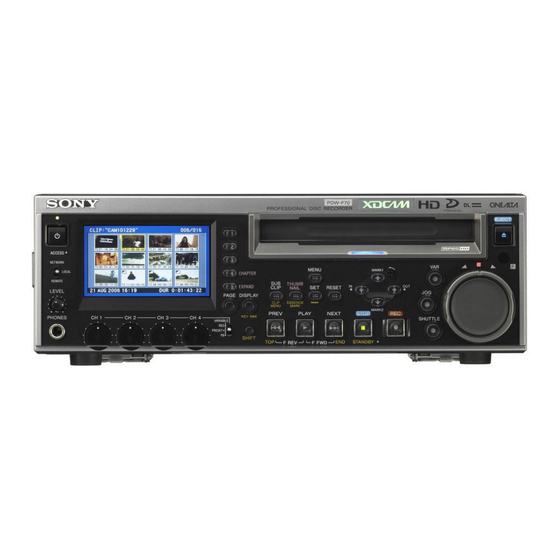
Page 12: Names And Functions Of Parts
Names and Functions of Parts Front Panel 1 On/standby 1 switch and indicator 2 ACCESS indicator 3 Remote control switch 4 LEVEL knob 5 PHONES jack 6 SHIFT button 7 MENU button 8 SUB CLIP/CLIP MENU button 9 THUMBNAIL/ESSENCE MARK button 1 Display and function menu section Handle 2 Audio level adjustment section... -
Page 13: Menu Button
Note Do not turn off the POWER switch on the rear panel or disconnect the power cord while the ACCESS indicator is lit. Doing so can result in a loss of data on the disc. c Remote control switch Different positions of the switch allow different operations, as follows. - Page 14 1 Display and function menu section q; Audio level meters qa Audio format qs Recording/playback format qd Time data type qf Time data display section qg System line number qh Clip number qj System frequency qk Audio monitor channels a Display Normally this displays the audio level meters, timecode, monitor pictures, and current settings.
-
Page 15: Audio Format
Note Use the largest size to display the system menu and view superimposed information. f Function menu Use the PAGE button to display this menu, and to switch between the pages (HOME, P1, P2) of the menu. Each page has five setting items, which correspond to the F1 to F5 buttons. - Page 16 r Audio monitor channels This displays the audio monitor channels, as set with MONI CH and MONI SEL on page P1 of the function menu (see page 82). When you are monitoring channels 1 and 2 (MONI CH is set to “CH 1/2”), the display changes as follows, depending on the setting of MONI SEL.
-
Page 17: Play Button
a VAR (variable) button To play back in variable-speed mode using the shuttle dial, press this button, turning it on. b JOG button To play back in jog mode using the jog dial, press this button, turning it on. c SHUTTLE button To play back in shuttle mode using the shuttle dial, press this button, turning it on. -
Page 18: Rear Panel
STANDBY button: Press this button to put the unit into standby-off mode (the STOP button lights, and the STANDBY indicator lights). Press it again to return to the original state (STOP button lit, STANDBY indicator off). This unit has a function that can put it into standby-off mode automatically after a certain length of time passes in Rear Panel 1 Analog video signal... - Page 19 2 Analog audio signal input/output section 1 AUDIO INPUT 1/3 and 2/4 connectors 2 AUDIO OUTPUT 1/3 and 2/4 connectors 3 AUDIO MONITOR AUDIO MONITOR AUDIO INPUT AUDIO OUTPUT a AUDIO INPUT (analog audio signal input) 1/3 and 2/4 connectors (XLR 3-pin, female) These connectors input two channels of analog audio.
- Page 20 (D-sub 9-pin, RS-422A compliant, female) To control this unit from a controller or VTR supporting the RS-422A Sony 9-pin VTR protocol, connect the device to this connector. When you use this connector, set the remote connector selector switch to the REMOTE(9P) side, and set INTERFACE SELECT >...
-
Page 21: Infrared Remote Commander
d Remote connector selector switch Push this switch to the side of the remote control connector you are using, either the RS232C connector or the REMOTE (9P) connector. S400 connector (6-pin, IEEE1394 compliant) Connect a DV device or computer using an i.LINK cable. The following connection types are supported. - Page 22 Press M to perform +5 times normal speed shuttle playback in the forward direction. Using the infrared remote commander Before use Pull out the insulation sheet. To replace the lithium battery in the remote commander The remote commander uses a CR2025 Lithium Battery. Do not use a battery other than the CR2025.
-
Page 23: Chapter 2 Preparations
Preparations Setting the System Frequency This unit is shipped with the system frequency still unset. Therefore, you need to set the system frequency before using the unit. (The unit cannot be used unless the system frequency is set.) Once it is set, the system frequency is retained even when the unit is powered off. -
Page 24: Connections And Settings
Connecting an External Monitor You can connect a video monitor to this unit’s video output connectors or to the MONITOR connector. The following figure shows an example using a Sony multi-format LCD monitor. You can also superimpose character information such as timecode and the unit’s operating status on output video. -
Page 25: Using Pdz-1 Over An I.link Connection (Fam Connection)
AUDIO PDW-F70 (this unit) MONITOR REF VIDEO INPUT COMPOSITE OUT AUDIO MONITOR TIME CODE ANALOG HD INPUT AUDIO INPUT AUDIO OUTPUT DIGITAL AUDIO (AES/EBU) INPUT OUTPUT HDSDI INPUT SDSDI OUTPUT HDSDI OUTPUT MONITOR RS232C CONTROL HDSDI MONITOR OUTPUT SDI signal input... -
Page 26: Connecting To A Nonlinear Editing System (Av/C Connection)
• This unit’s S400 connector has 6 pins. Check the number of pins on the i.LINK connector of your laptop computer, and use an appropriate i.LINK cable. REF VIDEO INPUT PDW-F70 (this unit) AC IN AUDIO INPUT POWER ANALOG HD INPUT... - Page 27 Remote connector selector switch: REMOTE(9P) unit as a recorder, and a BVE-700A as an editing control unit. To analog audio input connector HDSDI AUDIO PDW-F70 (this unit, player) OUTPUT MONITOR COMPOSITE OUT AUDIO MONITOR TIME CODE AC IN ANALOG HD INPUT...
- Page 28 HD video monitor (recorder) settings 75Ω termination switch: For details about the settings of the HDW-M2000/ M2000P, refer to the operation manual for that unit. PDW-F70 (this unit, player) When using the editing functions of the AC IN POWER recorder (connections using the S400...
-
Page 29: Editing Control Unit Settings
To composite video input connector To analog audio input connector COMPOSITE AUDIO PDW-F70 (this unit, player) MONITOR REF VIDEO INPUT COMPOSITE OUT AUDIO MONITOR TIME CODE ANALOG HD INPUT AUDIO INPUT AUDIO OUTPUT DIGITAL AUDIO (AES/EBU) INPUT OUTPUT HDSDI INPUT... -
Page 30: External Synchronization
XLR cable Ferrite core (supplied) 120 to 150 mm When the diameter of the XLR cable is too large to loop If the diameter of the XLR cable is so large that is difficult to loop the cable through the ferrite core, simply pass it through the core without looping. -
Page 31: Setup
Setup The principal setup operations before operating this unit are carried out using setup menus. This section explains how to set the date and time and how to adjust the brightness of the LCD panel. See Chapter 6 “Menus” (page 81) for more information about menu operations and menu items. - Page 32 E X T - 1 2 - 1 2 TC MODE - 2 0 - 2 0 P R E S E T - 3 0 - 3 0 ACCESS - 4 0 - 4 0 RUN MODE - 6 0 - 6 0 REC RUN 3 + 4...
-
Page 33: 23.98P) Mode Settings
24P (23.98P) Mode Settings Selecting the Playback Mode (23.98PsF or 2-3 Pulldown) When the setup menu item SYSTEM FREQ is set to “23.98P”, you can set monitor output to either 23.98PsF mode or 2-3 pulldown mode. Press the MENU button. The system menu (see page 83) appears. -
Page 34: Input And Output Signals In 24P (23.98P) Mode
SETUP MENU OPERATIONAL FUNCTION SYSTEM SEL SYSTEM FREQ : 601 * 60I 23.98P Press the m/MARK2 button to select “23.98P”. If you want to change the monitor output setting as well, press the </IN button to return to the higher level screen (the state of step 11). -
Page 35: Recording In 24P (23.98P) Mode
Timecode display Type 23.98PsF LTC display 24-frame timecode PDT display – VITC display 24-frame timecode COUNTER display 24-frame signals Timecode in remote timecode mode Type 23.98PsF 9-pin preset 24-frame timecode timecode 9-pin preset 24-frame signals timer 1 (Counter) 9-pin scene 24-frame timecode timecode 9-pin scene... - Page 36 The values of “24F TC” and “30F TC” under TIME CODE >PD PRESET in the setup menu are used as the conversion references. To display 30-frame pulldown timecode in the monitor video display section or on an external monitor Press the MENU button. The system menu (see page 83) appears.
-
Page 37: Superimposed Text Information
Superimposed Text Information The HDSDI signals output from the HDSDI OUTPUT 1 and 2 connectors and the MONITOR connector, the SDSDI signals output from the SDSDI OUTPUT connector, and the composite signals output from the COMPOSITE OUT connector can contain superimposed text information, including timecode, menu settings, and alarm messages. -
Page 38: Displaying Supplementary Status Information
Display Description The current menu settings are the same as the settings in menu bank 1. The current menu settings are the same as the settings in menu bank 2. The current menu settings are the same as the settings in menu bank 3. The current menu settings are the same as the factory defaults. - Page 39 On-screen Meaning indication INT REGEN-T&U The internal timecode generator is in synchronization with the playback timecode (LTC) read from disc. EXT LTC-T&U The internal timecode generator is in synchronization with the external timecode (LTC) input to the unit and is generating the same timecode values and user bit values as those of the external timecode (regeneration).
-
Page 40: Chapter 3 Recording And Playback
This unit uses the following disc for recording and playback: PFD23 Professional Disc (capacity 23.3 GB) 1) Professional Disc is a trademark of Sony Corporation. Note It is not possible to use the following discs for recording or playback: • Blu-ray Disc •... -
Page 41: Formatting A Disc
On/standby switch and indicator To unload Press the EJECT button. To load Insert a disc face up. The disc is drawn in. The disc slot indicator flashes orange when you insert a disc, and lights blue when the disc is completely loaded. The indicator flashes blue when you eject a disc, and goes out when the disc is completely ejected. - Page 42 Full salvage: Clips are reconstructed on the basis of markers recorded on the disc. Nonvolatile memory cannot be used, so processing takes longer than for a quick salvage (about 30 seconds, although it depends on the state of the disc). You are prompted to execute a full salvage whenever you insert a disc that was removed manually from a powered off device after interruption of recording by...
-
Page 43: Recording
Recording This section describes video and audio recording on the unit. See page 81 “Function Menu” in Chapter 6 for more information about function menu operations. See page 96 “Setup Menu Operations” in Chapter 6 for more information about setup menu operations. Note It is not possible to combine material recorded in different system frequencies and audio recording formats on a... - Page 44 To record timecode after setting an initial value (Internal Preset) To set an initial value 3,5 5 4,5 ACCESS NETWORK CHAPTER LOCAL REMOTE THUMB EXPAND CLIP NAIL LEVEL PAGE DISPLAY CLIP ESSENCE MENU MARK PREV PLAY CH 1 CH 2 CH 3 CH 4 KEY INHI...
-
Page 45: Carrying Out Recording
To cancel the user bits setting Press the MENU button. Press the SET button. The message “NOW SAVING...” appears, and the user bits set in step 3 are displayed. To record timecode that follows sequentially upon the last recorded timecode (Internal Regen) You can record timecode so that it is continuous from one clip to the next on the disc. - Page 46 ACCESS NETWORK CHAPTER LOCAL THUMB REMOTE EXPAND CLIP NAIL LEVEL PAGE DISPLAY CLIP ESSENCE MENU MARK PREV PLAY KEY INHI CH 1 CH 2 CH 3 CH 4 PHONES VARIABLE PRESET SHIFT F REV Insert a disc. Hold down the REC button, and press the PLAY button.
-
Page 47: Playback
Playback This section describes playback of video and audio on the unit. Before starting playback, make the following settings and adjustments. Selection of time data to display: Select with CNTR SEL on page P1 of the function menu. Selection of audio channels to monitor: Select with MONI CH and MONI SEL on page P1 of the function menu. - Page 48 To carry out playback again, move back to the desired clip using the PREV button, jog dial or shuttle dial. To set shot marks While playing back a disc, you can set essence marks such as SHOT MARK1 and SHOT MARK2 in desired frames. To set a SHOT MARK1 or SHOT MARK2, hold down the M/MARK1 or m/MARK2 button and press the SET button.
-
Page 49: Searching For Clips With Thumbnails (Thumbnail Search)
Playback in variable-speed mode starts. To stop playback in variable-speed mode, return the shuttle dial to the center position, or press the STOP button. To alternate between normal-speed playback and variable-speed mode playback Set the shuttle dial to the position corresponding to the desired variable playback speed, then switch between normal-speed playback and variable-speed mode playback by pressing the PLAY and VAR buttons alternately. -
Page 50: Searching With The Expand Function
Press the M/MARK1 button or m/MARK2 button to select CLIP INFORMATION. Press the SET button. A list of CLIP INFORMATION items appears. DATE: Date and time of recording TIME CODE: Timecode of the first frame in the clip DURATION: Recording time SEQUENCE NUMBER: Thumbnail sequence number See “To select a thumbnail image and start playback”... -
Page 51: Searching For Frames With Essence Marks
Note The maximum number of blocks may be larger than 1728 when the recorded duration of the clip is short. In this case, the frame interval of expanded thumbnails is fixed at 1 frame. This allows you to view expanded thumbnails at equal intervals. -
Page 52: Searching With The Chapter Function
Indicates that this is a list of frames containing the essence Sixth frame is selected from a mark (SHOT MARK1) total of 36 SHOT MARK1 frames Frame information (recording date and time, timecode, or total length) Currently selected SHOT MARK1 frame Recording date and time of the clip containing the selected frame... -
Page 53: Clip List Playback
Clip List Playback You can play back clips in the same order as in a clip list created using the scene selection function. See Chapter 4 for more information about scene selection. Playing back in clip list order Proceed as follows. If the clip list that you want to play exists on the disc, load it into the current clip list. -
Page 54: Locking (Write-Protecting) Clips
To perform repeat playback for clip list playback, load a clip list into the current clip list and then press the SUB CLIP button. Press the PLAY button. Playback starts from the saved playback position. Normal playback: When playback of the last clip finishes, it resumes from the start of the disc, repeatedly playing from the first through the last clip on the disc. -
Page 55: Deleting Clips
You return to the thumbnail screen, and a lock icon appears on the thumbnail of the selected clip to show that it is locked. Lock icon Locked clips cannot be deleted or set the thumbnail image (index picture) and so on. Unlock the clip if you want to perform any of these operations. -
Page 56: Assigning Sequence Numbers To Thumbnails
To cancel the deletion and return to the CLIP MENU Select “CANCEL”, and then press the SET button. Press the RESET or MENU button. Use the V/MARK1 button to select “OK”, and then press the SET button. The clip is deleted and you return to the thumbnail screen. -
Page 57: Chapter 4 Scene Selection
Scene Selection Overview What is scene selection? Scene selection is a function which allows you to select material (clips) from the material recorded on a disc and perform cut editing. You can do this by operating on this unit only. •... - Page 58 PAGE DISPLAY CLIP ESSENCE MENU MARK PREV CH 1 CH 2 CH 3 CH 4 KEY INHI PHONES VARIABLE PRESET SHIFT F REV PDW-F70 Disc ACCESS NETWORK MENU MARK1 CHAPTER LOCAL REMOTE EXPAND THUMB CLIP NAIL RESET LEVEL PAGE DISPLAY...
- Page 59 Clips Material recorded with this unit is managed in units called “clips”. A clip contains the material between a recording start point and a recording end point. Clips have numbers beginning with C, for example C0001. Recording start point of Recording end clip 2 point of clip 2...
-
Page 60: Assigning Clip Titles
Assigning Clip Titles When the setup menu item OPERATIONAL FUNCTION >CLIP TITLE >AUTO TITLE (see page 87) is set to “ENABLE”, titles are displayed instead of clip numbers for all clips recorded after the setting is made. Clip title Titles are made up of a prefix of up to 10 characters and a 5-digit number. - Page 61 To assign clip names on this unit The title assigned to clip becomes its clip name (file name). C0001.MXF TITLE00001 When sub item “AUTO NAMING” is set to “C****” TITLE00001.MXF TITLE00001 When sub item “AUTO NAMING” is set to “title” Set OPERATIONAL FUNCTION >CLIP TITLE >AUTO TITLE in the setup menu to “ENABLE”...
-
Page 62: Creating Clip Lists
Sequences of multiple s characters is converted into single s characters. The following alphabetic symbols can be displayed. : . ? ! # * / ( ) + - & @ = < > % " ; _ Display example JumpingDolphin_No103 JUMPINGDOsNO103 Creating Clip Lists... - Page 63 Press the MENU button. The CLIP menu appears (see page 71). (If no clip list is loaded in the current clip list, a screen as shown in step 3 appears.) Use the M/MARK1 or m/MARK2 button to select LOAD CLIP LIST, and then press the SET button. A clip list selection screen appears.
- Page 64 Use the arrow buttons or jog dial to select the desired clip. You can also select clips with the following operations. Press the PREV or NEXT button: Moves to the previous or next clip. Press the PREV or NEXT button with the SHIFT button held down: Moves to the first or last clip.
-
Page 65: Quick Scene Selection (Adding Sub Clips During Recording, Playback, Or Search)
Asterisk appears when clip list has not been saved to disc. • Even when a clip whose thumbnail is not the first frame is added to a clip list, the thumbnail displayed in the clip list is always the first frame as a thumbnail. To add sub clips using the expand function You can include a part of a sub clip in the current clip list by dividing the content of the sub clip into parts and... - Page 66 You can use a trimming operation (see page 68) to change In and Out points set by the quick scene selection function. 2,3,4 E X T - 1 2 - 1 2 - 2 0 - 2 0 TC MODE P R E S E T - 3 0 - 3 0...
-
Page 67: Editing Clip Lists
Editing Clip Lists You can select items from CLIP menus, and perform simple editing operations on clip lists and on sub clips registered in clip lists. Basic Operations E X T - 1 2 - 1 2 - 2 0 - 2 0 TC MODE P R E S E T... -
Page 68: Modifying The In And Out Points Of Sub Clips (Trimming)
previous or next page. Does not switch when there is only one page. Indicates that 2nd sub clip will be moved to position of 7th sub clip. I-shaped cursor showing position to which selected sub clip will be moved. To return to the clip list window without moving any sub clip Press the RESET button. -
Page 69: Deleting Sub Clips
The CLIP MENU appears after the trim is executed. If you press the SHIFT + SET buttons instead of the SET button, you return to the state after step 4 in “Basic Operations”, allowing you execute another trim. Save the current clip list to disc. For details, see “Saving the Current Clip List to Disc”... -
Page 70: Saving The Current Clip List To Disc
However, if you press the SUB CLIP button to turn it off, and then press it again to light it, the playback start position is reset to the start of the clip list. With the SUB CLIP button lit, press the PLAY button. You can repeat playback of the current clip list by setting SET UP >OPERATIONAL FUNCTION >REPEAT MODE to ON. -
Page 71: Managing Clip Lists
Use the supplied PDZ-1 Proxy Browsing Software. For details, see the PDZ-1 online help. Managing Clip Lists After you create or edit a clip list, you can use the CLIP menu to save it to disc, load it from disc into unit memory, and delete it from the disc. -
Page 72: Changing Displayed Items Of Information On Sub Clips
Note The CLIP menu can handle up to 99 clip lists. Changing Displayed Items of Information on Sub Clips You can change information displayed in the lower portion of each thumbnail in the clip list window. Proceed as follows. Display the CLIP menu. See “Displaying the CLIP menu”... - Page 73 See “Displaying the CLIP menu” (page 71). Use the M/MARK1 or m/MARK2 button to select “SORT CLIP LISTS BY...”, and then press the SET button. A screen like the one shown below appears. Use the M/MARK1 or m/MARK2 button to select the type of sorting.
-
Page 74: Using The Pdz-1 Proxy Browsing Software
Using the PDZ-1 Proxy Browsing Software When a computer with the PDZ-1 Proxy Browsing Software installed is connected to this unit, you can transfer the proxy AV data and metadata files recorded on a disc to the computer. On the computer side, PDZ-1 enables you to browse the proxy AV data, add or modify metadata (titles, comments, essence marks, etc.), or create a clip list. -
Page 75: Chapter 5 File Operations
File Operations Overview A remote computer can be connected to this unit and used to operate on recorded data which has been saved in data files, such as video and audio data files. Use FAM (file access mode) for the computer connection. Directory Structure The following figure shows the directory structure of discs visible to a remote computer. -
Page 76: File Operation Restrictions
File Operation Restrictions This section explains which operations are possible on files stored in each directory. When required, the following operation tables distinguish reading and writing from partial reading and writing. Root directory File name Content INDEX.XML Contains data for management of the material on the disc. - Page 77 Notes • Directories cannot be created in the Clip directory. • When the following operations, supported by version 1.5 and higher XDCAM devices, are carried out on a disc, then it becomes impossible for version 1.4 and lower XDCAM devices to record new clips or delete existing clips on that disc.
-
Page 78: File Operations In File Access Mode
a) UTF-8 file names can be up to 63 bytes in length. (Depending on the character type, file names (including extension) may be limited to 21 characters.) b) Only when the Write Inhibit tab on the disc is set to enable recording and “REC INH”... -
Page 79: Operating On Files
The “Unplug or Eject Hardware” dialog box (Windows 2000) or the “Safety Remove Hardware” dialog box (Windows XP) appears. Select “Sony XDCAM PDW-F70 IEEE 1394 SBP2 Device” and click “Stop”. The “Stop a Hardware device” dialog appears. Select “Sony XDCAM PDW-F70 IEEE 1394 SBP2 Device”... - Page 80 To disable FAM connections Execute one of the procedures described in the previous section “To make a reconnection” to make a FAM connection between this unit and the remote computer. To disable FAM connections, in the setup menu, set INTERFACE SELECT >i.LINK MODE to “AV/C” (see page 94).
-
Page 81: Function Menu
Menus Function Menu The function menu provides access to frequently used settings, such as input video signal selection and timecode settings. Menu settings are stored in nonvolatile memory and are preserved even after the unit is powered off. Function Menu Operations The function menu appears on the LCD panel of this unit. - Page 82 Setting item Description F3: A2 INPUT (audio input Selects the audio input signals assigned to audio channels 2 F5: A4 INPUT (audio input and 4. HDSDI: Audio signal multiplexed into HDSDI signal ANALOG2: Analog 2 audio signal AES/EBU: Signals input to DIGITAL AUDIO (AES/ EBU) INPUT 1/2 and 3/4 connectors...
-
Page 83: System Menu
Setting item Description F2: TC MODE (timecode When TCG is set to “INT” mode) Selects whether the count value advances from a preset initial value, or advances consecutively from the timecode of the last frame recorded on the disc. PRESET: Advance from a preset initial value. -
Page 84: Setup Menu
Press the M/MARK1 or m/MARK2 button to select SETUP MENU or DISC MENU. Press the ,/OUT button. The setup menu (see page 86) or the disc menu (see page 98) appears. Setup Menu As shown in the following figure, the setup menu has three levels. - Page 85 OPERATIONAL FUNCTION SETUP MENU DISPLAY CONTROL TIME CODE DISC PROTECTION VIDEO CONTROL (Continued) Top level Second level REPEAT MODE AUTO EE SELECT LOCAL ENABLE REC FORMAT DISC END CLIP TITLE FILE NAMING SYSTEM SEL SEARCH ENABLE VAR SPD LIMIT PREROLL TIME AFTER CUE-UP ASM POSTROLL CHARA.
-
Page 86: Setup Menu Items
a) BLACK LEVEL when the system frequency is 50I/25P Setup Menu Items The purpose and settings of the setup menu items are described below. • Brackets [ ] indicate characters and symbols that appear in the time data display section. OPERATIONAL FUNCTION [Operational]: Operation settings REPEAT MODE [>... - Page 87 OPERATIONAL FUNCTION [Operational]: Operation settings AUTO EE SELECT [> Auto DISC OUT [>> DISC OUT]: EE]: Determine whether When no disc is loaded. the unit enters E-E mode or PB mode when audio F.FWD/REV [>> F.FWD/ and video signals from REV]: Operations when other equipment are input.
- Page 88 OPERATIONAL FUNCTION [Operational]: Operation settings SEARCH ENABLE [> Search ENA]: Specify how to put the unit into a search mode (jog, shuttle, or variable-speed). VAR SPD LIMIT [> VAR limit]: Specify whether to limit the speed of variable speed playback PREROLL TIME [>...
- Page 89 DISPLAY CONTROL [Display]: Settings related to display on the LCD panel of this unit and on an external monitor DISPLAY INFO [> DISP info]: Select the content of the character information shown in the monitor video section and on an external monitor. SUB STATUS [>...
- Page 90 TIME CODE [Time Code]: Settings related to the timecode generator TCG REGEN [> TCG regen]: Select the signals to generate when the timecode generator is set to regenerate mode (TC MODE on page P2 of the function menu is set to “REGEN”).
- Page 91 DISC PROTECTION [Disc protct]: Settings related to disc protection STILL TIMER [>> STL timer]: Specify the length of time the unit can be in still image mode before switching to disc protection mode. VIDEO CONTROL [Video]: Settings related to video control INT VIDEO SG [>...
- Page 92 VIDEO CONTROL [Video]: Settings related to video control PROCESS CONTROL VIDEO GAIN [>> V gain]: [> Proc ctrl]: Separate adjustment screens appear for the following CHROMA GAIN [>> C gain]: items. Use the jog dial to make settings, and press the MENU button to return from the adjustment CHROMA PHASE [>>...
- Page 93 AUDIO CONTROL [Audio]: Settings related to audio control REC MODE [> REC mode]: Select the audio recording mode. *4ch×16bit [>> 4ch/16bit]: 4-channel, 48-kHz mode DATA MODE [> Data mode]: CH1/CH2 IN [>> CH1/CH2]: Specify whether to handle Specify for the input to digital audio signals as the DIGITAL AUDIO non-audio signals during...
- Page 94 RS232C connector, depending on the setting of the remote connector selector switch. 9PIN(PARA)[>> Para Run]: Use the REMOTE(9P) connector to connect several PDW-F70 units and perform remote control from one of them specified as the parent. *9600 [>> 9600] 19200 [>>...
- Page 95 METADATA [Metadata]: Metadata settings ESSENCE MARK [> SDI OUT [>> SDI out]: Select EssnceMk] whether to output essence marks in the VANC of HD/SDSDI output. SD VANC LINE [>> SDI line]: When SDI OUT is set to “ON”, select the line of SDSDI output in which to output essence marks.
-
Page 96: Setup Menu Operations
MENU GRADE [Menu grade]: Selection of menu items to be displayed Determine whether to display basic items only or both basic and enhanced items in the monitor video section and the time data display section when using the setup menu. Setup Menu Operations This section explains how to change menu settings. -
Page 97: Displaying Enhanced Items
SETUP MENU DISPLAY CONTROL CHARA.DISPLAY CHARA.POSITION :WHITE CHARA.TYPE CHARA.VSIZE DISPLAY INFO :T&STA SUB STATUS :OFF :WHITE MENU DISPLAY :55% BRIGHTNESS ALARM Press the ,/OUT button. This displays all possible settings for the item selected in step 3. SETUP MENU DISPLAY CONTROL SUB STATUS :OFF * OFF... -
Page 98: Disc Menu
With this done, when you press the MENU button and the ,/OUT button to display the setup menu, all basic and enhanced items on menu level 1 appear. SETUP MENU OPERATIONAL FUNCTION DISPLAY CONTROL TIME CODE DISC PROTECTION VIDEO CONTROL AUDIO CONTROL INTERFACE SELECT METADATA... -
Page 99: Disc Menu Operations
FILE SYSTEM TO MENU MENU KEY If you selected CLIP, the status of the current clip appears. CLIP STATUS CLIP LIST MODE CLIP LIST NEME TITLE: PDW-F70 RECORD DEVICE SERIAL 06/3/02 DATE TIME 19:54:38 TO MENU MENU KEY When playback or search reaches a new clip, the display changes to the status of the new clip. - Page 100 Press the MENU button. To clear the menu from the screen Press the MENU button twice. To delete all clips Note Carrying out the following procedure deletes all clips that are not locked. Proceed as follows. Display the disc menu (see page 83). Press the M/MARK1 button or the m/MARK2 button to select DELETE.
-
Page 101: Chapter 7 Using Option Boards
For safety, always have option boards installed by a trained technician. Refer to the operation manual supplied with each board for information about installing, configuring, and operating the board. Contact your Sony dealer regarding installation of option boards. Using the PDBK-101 Network Board (Gigabit Ethernet) -
Page 102: Using The Pdbk-102 Mpeg-Ts Input/Output Board
F FWD STANDBY The following example shows a connection between this unit and an HDV camcorder. Notes • Install the PDBK-102 in option slot 2. standard (called “HDV are trademarks of Sony Corporation and Victor PDW-F70 ACCESS MARK1 NETWORK MENU CHAPTER... -
Page 103: Using The Pdbk-103 Analog Hd Input Board
PRESET SHIFT F REV F FWD STANDBY PDW-F70 Notes • Install the PDBK-103 in option slot 2. • The PDBK-102 and PDBK-104 cannot be used when the PDBK-103 is installed. • Select YPbPr signals or RGB signals in the input video selection menu. -
Page 104: Using The Pdbk-104 Sd Input Upconverter Board
CH 4 PHONES VARIABLE PRESET SHIFT F REV PDW-F70 Notes • Install the PDBK-104 in option slot 2. • The PDBK-102 and PDBK-103 cannot be used when the PDBK-104 is installed. • Select SDSDI or composite signals in the input video selection menu. -
Page 105: Appendix
In the event of operating problems If you should experience problems with the unit, contact your Sony dealer. Use and storage locations Store in a level, ventilated place. Avoid using or storing the unit in the following places. -
Page 106: Periodic Maintenance
Any of the items can be reset during periodic maintenance or parts replacement. Resetting items allows you to roughly determine the timing of next periodic maintenance. For display resetting, contact your Sony dealer. Item name (name between Description [ ] is name in the time data... -
Page 107: Troubleshooting
Reset the settings in the setup menu (see page 84). Reset the settings in the setup menu (see page 84). If the same message appears after you reset the settings, contact your Sony dealer. The NVRAM battery is exhausted. Contact your Sony dealer. Troubleshooting... - Page 108 When a disc is inserted Alarm message in time Alarm message in monitor video data display section section Unknown FS! UNKNOWN FILE SYSTEM. PLEASE FORMAT DISC OR EJECT. No FS! NO FILE SYSTEM.PLEASE EJECT DISC. Eject the disc. ILL. Disc! IRREGULAR DISC IS USED.
- Page 109 Alarm message in time Alarm message in monitor video data display section section DISC TOP. Disc Top! DISC END. Disc End! MAX # Files DISC CANNOT BE RECORDED TO. FOR MORE RECORDING SPACE, DELETE CLIPS OR NON-AV DATA. (GENERAL FILES) DISC CANNOT BE RECORDED TO.FOR MORE RECORDING SPACE, DELETE OTHER CLIP LISTS.
- Page 110 Alarm message in time Alarm message in monitor video data display section section CLIP LIST CANNOT LOCATE SPECIFIED No SUB CLIP SUB CLIP(S). TO ADD AN ESSENCE MARK, EXIT SB CLP mode FROM SUB CLIP MODE FIRST. SUB CLIP IS INVALID. SUB CLIP NG SET APPROPRIATE IN/OUT POINTS.
- Page 111 Alarm message in time Alarm message in monitor video data display section section DISC CANNOT BE RECORDED. HD 60I HD 60I/30P or HD 30P CLIP(S) EXIST. DISC CANNOT BE RECORDED. HD 50I HD 50I/25P or HD 25P CLIP(S) EXIST. DISC CANNOT BE RECORDED. HD HD 23P Disc 23.98P CLIP(S) EXIST.
-
Page 112: During Playback
During playback Alarm message in time data display section 525/60 Disc 625/50 Disc HD 60I/30P HD 50I/25P! HD 23P Disc Disc Error! a) Displayed only when DISPLAY CONTROL >ALARM is set to “ON” or “LIMITED”. Troubleshooting Alarm message in monitor video section DISC CANNOT BE PLAYED BACK. - Page 113 During thumbnail search, scene selection, and clip list operations Alarm message in monitor Description/action video section CANNOT EXPAND CLIP The clip cannot be expanded into more blocks. ANY FURTHER. This appears when the EXPAND button is pressed when the number of block is maximum, or when the duration of an expanded thumbnail is 1 frame.
-
Page 114: Error Messages
IEEE 1394 proposed by Sony, is a trademark supported by many companies worldwide. IEEE 1394 is an international standard defined by IEEE, the Institute of Electrical and Electronics Engineers, Inc. -
Page 115: Specifications
Use Sony i.LINK cables Use Sony i.LINK cables to connect the i.LINK devices. 6 pins y 4 pins (For DV dubbing) 6 pins y 6 pins (For DV dubbing) i.LINK and are trademarks. - Page 116 Playback format Video MPEG HD: HQ35/SP25/LP18 Mbps DVCAM: 25 Mbps Proxy video MPEG-4 Audio MPEG HD: 16 bits/48 kHz, 4/2 channels DVCAM: 16 bits/48 kHz, 4 channels Proxy audio A-law 8 bits, 8 kHz, 4 channels 1) The MPEG-4 Codec is a product of Ingenient Technologies, Inc. Recording/Playback time (when PFD23 is used) MPEG HD Mode...
- Page 117 STORAGE SYSTEMS TO RECORD CONTENT OF ANY TYPE. • Always verify that the unit is operating properly before use. SONY WILL NOT BE LIABLE FOR DAMAGES OF ANY KIND INCLUDING, BUT NOT LIMITED TO, COMPENSATION OR REIMBURSEMENT ON ACCOUNT OF THE...
-
Page 118: Using Umid Data
Using UMID Data Metadata is additional information recorded on discs along with audio-visual data. It is used to bring greater efficiency to the flow of operations from material acquisition through editing, and to make it easier to find and reuse material. As one of application of metadata, the UMID has been internationally standardized. - Page 119 • Distinguishing between original material and copied material. 00 is added to the Instance Number for original material. • Recording with UTC time. UTC (coordinated universal time) is used when recording the UMID. Use of a universal time system enables uniform management of source material recorded all over the world.
-
Page 120: Mpeg-4 Visual Patent Portfolio License
MPEG-4 Visual Patent Portfolio License This product is licensed under the MPEG-4 Visual Patent Portfolio License for the personal and non-commercial use of a consumer for (i) encoding video in compliance with the MPEG-4 Visual Standard (“MPEG-4 Video”) and/or (ii) decoding MPEG-4 Video that was encoded by a consumer engaged in a personal and non-commercial activity and/or was obtained from a video provider licensed by MPEG LA to provide MPEG-4 Video. -
Page 121: Glossary
Glossary AES/EBU A standard established jointly by the AES (Audio Engineering Society) and EBU (European Broadcasting Union) for serial transmission of digital audio. Two channels of audio can be transmitted via a single connector. Clip A recording unit. Clips are created every time recording starts and stops. - Page 122 globally unique number and a material number for the identification of recorded material. An optional section called the “Source Pack” contains information such as the time and location of recording. A UMID with the Basic section only is called a Basic UMID.
-
Page 123: Index
Index AC IN connector 20 ACCESS indicator 12 Alarms 107 Arrow buttons 16 Audio format 15 AUDIO INPUT 1/3 and 2/4 connectors Audio level meters 15 Audio monitor channels 16 AUDIO MONITOR connectors 19 AUDIO OUTPUT 1/3 and 2/4 connectors 19 Audio recording formats 43 levels 46... - Page 124 JOG button 17 Jog dial 17 Jog/shuttle transport indicators 17 KEY INH 15 KEY INH button 14 Key operation inhibit mode 15 LEVEL knob 13 Loading and unloading a disc 40 MARK1 button 16 MARK2 button 16 MENU button 13 Menus 81 MONITOR connector 18 Monitor video display section 14...
- Page 125 changing 50 displaying a list 49 specifying the frame 46 starting playback with 49 Thumbnail search 49 changing an image 50 changing the clip information 49 displaying a list of thumbnail images 49 selecting an image 49 TIME CODE IN connector 20 TIME CODE OUT connector 20 Time data display section 15 Time data type 15...
- Page 126 Sony Corporation...