Table of Contents

Related Manuals for Boss MX1-3HL


Summary of Contents for Boss MX1-3HL
- Page 1 BOSS Mini Mechanical Pressurisation Equipment Mini Models (MX1-3HL, MX2-3HL) Operation & Maintenance Manual Rev 2.1 Rev 2.1 Oct-15 Page 1 / 28 We reserve the right to change designs and technical specifications of our products www.bssindustrial.co.uk...
-
Page 2: Customer & Equipment Details
Purchase From: Note: It is highly recommended to have this equipment commissioned by a BOSS approved engineer. Any damage or loss incurred through incorrect commissioning by an unapproved engineer will not be covered by the warranty. If you wish for BOSS to arrange this please contact us. (See contact details) Please see the warranty section for details. -
Page 3: Commission Record
Commissioning Record FILL IN RECORD TO VALIDATE WARRANTY OF PRESSURISATION UNIT Site Reference: PU Reference: Date Commissioned: Engineer Name: Company: PUMP CONTROL PRESSURE SWITCH HIGH/LOW PRESSURE SWITCH RANGE: HIGH PRESSURE - CUT OUT DIFFERENTIAL: LOW PRESSURE - CUST IN Delete as PUMPS NUMBER: 1 / 2 LOW PRESSURE - DIFF... -
Page 4: Table Of Contents
14 - 16 Hydraulic Commissioning 17 - 18 Maintenance Maintenance information Wiring Wiring Diagram Spares Mini Models (MX1-3HL, MX2-3HL) 21 - 22 Troubleshooting Service Log 24 - 25 Warranty Information Rev 2.1 Oct-15 Page 4 / 28 We reserve the right to change designs and technical specifications of our products... -
Page 5: About This Manual
About this Manual This Operation and Maintenance Manual contains all the necessary information to install, commission, operate and maintain Flexfiller pressurisation equipment. It is recommended to read all parts of this manual before undertaking any work on the equipment. Conventions used in this Manual This manual makes use of symbols to identify key pieces of information. -
Page 6: Equipment Overview
Equipment Overview The function of this pressurisation unit is to provide a means of automated water top-up to sealed heating and cooling systems. The equipment is designed to provide periodic water top-up to compensate for minor losses in system pressure (e.g. slow leaks, air venting, etc.). This equipment is not designed to cope with sudden losses of system pressure (e.g. -
Page 7: Important Information
IMPORTANT INFORMATION Environment It is not anticipated that this equipment will be exposed to adverse environmental conditions without additional protection. Site the equipment in a frost free area. Ensure that 100 mm of clear access is available around the equipment with 500 mm clear access at the front. -
Page 8: Installation
Installation This pressurisation unit is not designed to be installed in an outdoor environment. The unit must be installed in a frost free environment, away from precipitation and water sprays/jets. If there is a risk of flooding, the unit must be installed on a raised plinth. Please refer to the appropriate datasheet for the maximum working pressure and temperature of the pressurisation unit. -
Page 9: Flow Restrictors
Installation of mini mechanical units Remove the appropriate coverings. Ensure that the float valve is set to its lowest position. All pipework connections are to be made with appropriate proprietary jointing compound. PTFE is not permitted. Connect the overflow pipework. -
Page 10: Flow Restrictors
If no restrictor is required, the filter must be removed from one of the restrictors and installed on its own. The following diagram shows how to remove the filter: To install the flow restrictor/filter, hold it by the tab and push it into the opening of the float valve connection, as shown in the diagram below: Rev 2.1 Oct-15 Page 10 / 28... -
Page 11: Mini Clearance And Connection Requirements
Mini MX-HL Clearance and Connection Requirements Connection Size Notes An isolation valve must be installed on the mains water feed for Mains Water Feed ½” BSP M servicing. Guidance on drainage requirements should be obtained from the Break Tank Overflow 22 mm local water authority. -
Page 12: Electrical Power Supply
Electrical Power Supply This equipment must be electrically isolated before removing the covers. Cables connected to the volt free contacts may be supplied from another source and may remain live after the unit is isolated. These must be isolated elsewhere. All electrical connections must be carried out by a suitably qualified and competent person. -
Page 13: Commissioning
Commissioning It is highly recommended to have this equipment commissioned by a BOSS approved engineer. Any damage or loss incurred through incorrect commissioning by an unapproved engineer will not be covered by the warranty. Pre-Commissioning Checklist The following conditions must be met before starting the commissioning process. Failure to meet these conditions may result in injury or damage to the equipment, system and property. -
Page 14: Commissioning
Commissioning Commissioning must be carried out by a trained and competent person. Close the system connection valve. (isolation valve) Turn on the unit, the current pump pressure is shown on the mounted gauge. Adjust the pressure (Cold fill pressure) using the pressure switch (black screw) ... - Page 15 To change the pressure gauges turn the screw slightly. Black screw for Range setting Silver screw for Differential (Diff) Pressure setting for switches with automatic reset. 1. Set the cut-in pressure on the “CUT-IN” scale (range scale), 2. Set the differential on the “DIFF” scale. High and Low Pressure Settings (Boiler control) The high pressure switch is pre-set to cut out at 3.0 bar(g) and will not re-set until the system pressure has dropped to 2.0 bar(g).
- Page 16 To change the pressure gauges see below how to Rev 2.1 Oct-15 Page 16 / 28 We reserve the right to change designs and technical specifications of our products www.bssindustrial.co.uk...
-
Page 17: Hydraulic Commissioning
Hydraulic Commissioning 1 – Float Valve Setting Ensure that the break tank float valve is set to its lowest position: Mini Units If a drain valve is fitted to the break tank, ensure that it is closed. Then, turn on the mains water supply and allow the break tank to fill. - Page 18 Turn on the power supply to the pressurisation unit. Depending on the current system pressure, the unit will respond in one of the following ways: If the system pressure is below the low pressure adjust the pressure switch by turning the black screw clockwise.
-
Page 19: Maintenance
Maintenance Before carrying out any maintenance please remember to first electrically isolate the equipment and then hydraulically isolate the equipment. Please ensure that competent trained engineers are used to carry out any service or maintenance work. It is recommended that the system as a whole is serviced and inspected annually. At that time the gas charge within the system expansion vessel (if appropriate) should be checked and verified as equal to the cold fill pressure set on this pressurisation unit. -
Page 20: Wiring Diagram
Wiring diagram Rev 2.1 Oct-15 Page 20 / 28 We reserve the right to change designs and technical specifications of our products www.bssindustrial.co.uk... -
Page 21: Mini Models (Mx1-3Hl, Mx2-3Hl)
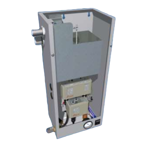
Therefore, the drawings may not accurately reflect the current production design. If in any doubt about the compatibility of replacement parts, please contact BOSS. Mini Models (MX1-3HL, MX2-3HL) *Image for indication only Rev 2.1 Oct-15 Page 21 / 28 We reserve the right to change designs and technical specifications of our products www.bssindustrial.co.uk... - Page 22 Rocker switch BSS F014 6 mm Poly-tube BSS M014 8 mm Poly-tube BSS M015 Pump Control Pressure Switch FC TBV BOSS High/Low Pressure Switch FC TBV TWIN Fused Terminal Block BSS R002 Pump – All Models (Model E EP77) BSS M024...
-
Page 23: Troubleshooting
Troubleshooting If for any reason the pressurisation unit does not seem to be functioning correctly, please refer to the table below for a list of solutions to known problems. If the pressurisation unit is showing a fault code on the display, holding down the [SET] button will cause the current system pressure to be temporarily shown on the display. -
Page 24: Service Log
Service Logs This service log should be completed by the service engineer after each annual service. Date Range Engineers Name Differential Company Contact Number Comments Date Range Engineers Name Differential Company Contact Number Comments Date Range Engineers Name Differential Company Contact Number Comments Date... - Page 25 Date Range Engineers Name Differential Company Contact Number Comments Date Range Engineers Name Differential Company Contact Number Comments Date Range Engineers Name Differential Company Contact Number Comments Date Range Engineers Name Differential Company Contact Number Comments Rev 2.1 Oct-15 Page 25 / 28 We reserve the right to change designs and technical specifications of our products www.bssindustrial.co.uk...
-
Page 26: Warranty Information
If the unit is identified with a manufacturing defect then no charge is made for correcting the defect. The BOSS equipment is manufactured to order and is clearly marked, where applicable, with a unique serial number, allowing traceability to both individual model configuration and the engineer or site responsible for the build and test. - Page 27 Notes Rev 2.1 Oct-15 Page 27 / 28 We reserve the right to change designs and technical specifications of our products www.bssindustrial.co.uk...
- Page 28 BSS Industrial Fleet House Lee Circle Leicester LE1 3QQ United Kingdom Rev 2.1 Oct-15 Page 28 / 28 We reserve the right to change designs and technical specifications of our products T +44 116 256 7052 www.bssindustrial.co.uk F +44 116 253 1343 technicalteam@bssgroup.com...