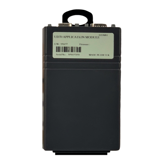
Summary of Contents for Control Techniques UD70
- Page 1 Installation Guide UD70 MD29 Second Processor Options for Unidrive and Mentor II Part Number: 0460-0098 Issue Number: 3 www.controltechniques.com...
- Page 2 Copyright © 25/1/02 Control Techniques Drives Ltd Issue Code: Hardware: UD70 All Issues, MD29 Issue 3 and later Firmware:...
-
Page 3: Table Of Contents
Contents Mechanical Installation Unidrive and UD70 Mentor II and MD29/MD29AN Electrical Installation UD70 MD29 MD29AN RS232 Port Connections RS485 Port Connections I/O Box Port Connections (MD29 Only) Digital I/O Connections RS485 Port Configuration Node Address Data Rate RS485 Port Communications Modes... -
Page 4: Mechanical Installation
DC link capacitors have completely discharged. Unidrive and UD70 • Slide the UD70 module under the display panel of the Unidrive, and push the module in until the connector locates with the plug inside the Unidrive. UD70/MD29 Installation Guide www.controltechniques.com... - Page 5 Apply firm pressure, and the module will click securely into place. • To remove the UD70, pull firmly on the black tab, and the module will disengage from the connector. Do not attempt to remove the UD70 module while the Unidrive is still powered up, as this may cause damage to the Unidrive.
-
Page 6: Mentor Ii And Md29/Md29An
The MD29 is fitted onto the 40-way pin header (PL1) on the MDA2B circuit board. The supplied mounting pillars should be attached to the MDA2B on the Mentor II. • Tilt the MD29 at an angle and locate the first few pins into the MD29 header. UD70/MD29 Installation Guide www.controltechniques.com Issue Number: 3... - Page 7 Do not attempt to remove the MD29 while the Mentor II is still powered up, as this may cause damage to the Mentor II. WARNING UD70/MD29 Installation Guide Issue Number: 3 www.controltechniques.com...
-
Page 8: Electrical Installation
Electrical Installation UD70 The UD70 provides a dedicated RS232 programming port (Connector C) and a general purpose RS485 communications port (Connector D).. Connectors A and B provide the connectors for high speed fieldbus communication options, if fitted. Refer to the appropriate fieldbus option User Guide for full fieldbus connection details. -
Page 9: Md29An
The pin connections for the RS485 port are given in the table below 0VSC is completely isolated from the main Unidrive and Mentor II 0V. Function Description 0VSC 0VSC Isolated 0V for serial communications link. Inverted transmit line Inverted transmit line Transmit line Receive line UD70/MD29 Installation Guide Issue Number: 3 www.controltechniques.com... - Page 10 4 Wire RS485 Network The diagram below shows the connections required for a 4 wire RS485 network, using a master controller with an RS485 port. The UD70 and MD29 can be configured to act as master controllers, but this requires DPL programming to control the network.
-
Page 11: I/O Box Port Connections (Md29 Only)
Inverted Transmit line Receive line /RxA Inverted Receive line To use the I/O Box with UD70 or MD29AN, connect it to the RS485 port, and NOTE select Mode 10 communications. Digital I/O Connections The RS485 connector has 2 TTL digital inputs and 1 TTL digital output. They are used in conjunction with the Timer/Counter unit. -
Page 12: Rs485 Port Configuration
The RS485 port is configured by setting certain user parameters on the Unidrive or Mentor II. These control individual features about the port. Any changes take effect when the configuration parameters are stored and the UD70 or MD29 is reset. The following parameters used to configure the RS485 port. -
Page 13: Data Rate
Mentor II to communicate with standard CT software packages, such as UniSoft, MentorSoft, SystemWise, etc. Menu 0 parameters are not accessible through a UD70 or MD29. Refer to the User's Guide for MD29 or UD70 for a detailed description of the ANSI protocol. - Page 14 Mode 14 - 4 Wire Modbus ASCII Slave Mode Mode 16 - 2 Wire Modbus ASCII Slave Mode The UD70 and MD29 will communicate using the Modicon Modbus ASCII protocol with a 4-wire or 2-wire connection. The data frame used for Modbus RTU is 1 start bit, 7 data bits, no parity, 2 stop bits.
-
Page 15: Storing Configuration Parameters
I/O Box Mode (UD70 and MD29AN only) Mode 10 - I/O Box Mode Unlike the MD29, the UD70 and MD29AN do not have a dedicated port for use with the I/O Box. The general purpose RS485 port can be configured to communicate directly with an I/O Box by configuring the RS485 port to use Mode 10 communications.


