Scotsman SCN60 Manual
Residential nugget ice machine
Hide thumbs
Also See for SCN60:
- Installation and use manual (37 pages) ,
- Installation and user manual (18 pages) ,
- Manual (2 pages)
Table of Contents
Advertisement
Advertisement
Table of Contents

Related Manuals for Scotsman SCN60


Summary of Contents for Scotsman SCN60
- Page 1 SCN60 Residential Nugget Ice Machine...
- Page 2 SCN60 Nugget Ice • Nugget Ice – What it isn’t: Ice frozen in a mold – What it is: A chewable ice, formed continuously by forcing soft ice thru tapered holes.
- Page 3 Components • Compared • But it does to cube ice have: machines: – Auger – Gear reducer – No spray pump – Float valve – No spray jets – No hot gas valve – No inlet water solenoid valve...
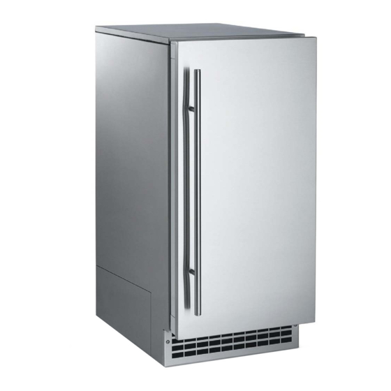
- Page 4 SCN60 Cabinet • 15 inch wide cabinet • Can be built in – air in and out the front • Service panel on side • Finishes – Unfinished door • For decorator door – Stainless door ...
- Page 5 In the Bin Dataplate Light Bin Level Sensor Ice Outlet Chute...
- Page 6 In the Bin Condensate Drain Hose Scoop Holder Drain...
- Page 7 Cabinet • Air in and out the front • Front Service Panel • Kickplate – Access to condenser...
- Page 8 Side Service Panel Provides access to bin drain, drain pump (when used), fan motor and compressor. Side access panel now on ALL SC Models!!
-
Page 9: Reverse Door Swing
Reverse Door Swing • Remove hinge covers • Loosen the screw on the keyhole slot, remove the other • Pull door from unit • Switch hinges on door... - Page 10 Reverse Door Swing • Remove top panel • Remove and replace top bracket...
- Page 11 Reverse Door Swing • Remove and replace lower door bracket – New brackets shipped loose inside the bin – Hardware package includes opposite door hinge covers, 90 degree door stop pin & leveling leg caps...
-
Page 12: Door Panel
Door Panel Hole Cover • Unfinished units are shipped without door covers – Use White, Black or Stainless Scotsman panel kits • Panel kits include hole covers – Make and attach a ... -
Page 13: Installation
Installation • Power – 115 volt model with power cord • Water – ¼” OD copper tube on back, compression fitting ships in attached bag • Drain – Gravity model – Pump model or kit... - Page 14 Electrical • 115 volt, 60 Hz power • Unit must be on separate 15 amp circuit • Outlet should be accessible or must use circuit breaker to shut off power during service • No extension cords permitted...
-
Page 15: Water Supply Connection
Water Supply Connection • Connection on back • Compression fitting shipped with unit • 20 to 80 lb pressure • Coil inlet tubing to this fitting when unit built in... - Page 16 Drain • Gravity • Drain Pump – Connect to hose inside – Hose pre‐connected cabinet‐field supplied – Route to drain – Drain tubing must not – Maintain code air gaps trap water – Pump will activate – Vent and use rigid when water backs up tubing outside of into inlet hose cabinet – Route and slope to drain – Maintain code air gap...
-
Page 17: Control Panel
Control Panel Check Water Light- Clean- On/Off Reset Status Light- Time-to-Clean Green Indictor Light- Yellow... -
Page 18: Initial Start-Up
Initial Start Up • Connect power • Compressor, Fan Motor and Auger – Panel lights blink Drive Motor • Turn on water operate supply • In about 10 minutes • Push On‐Off button ice will begin to fall – Ice making light into the bin switches ON... - Page 19 Control Panel – Ice Making Mode • Green Light – Indicates ready to make ice – Does not indicate operation, bin full or empty...
- Page 20 Control Panel – Check Water • Red Light – Indicates Lack of Water to Machine – No ice will be made while light is on – Restarts automatically when water restored...
- Page 21 Control Panel – Time to Clean • Yellow Light – On after 6 months of power up time – Indicates the machine needs to be cleaned • Scale removed • Condenser cleaned • Unit sanitized...
- Page 22 Ice Making Components Refrigeration outlet • Evaporator – Stainless steel refrigerated tube with vertical riflings – Refrigeration coil wrapped on outside of tube & foamed Refrigeration inlet Water inlet...
- Page 23 Ice Making Components • Auger – Double‐flighted, solid stainless steel auger Water Seal...
- Page 24 Ice Making Components • Breaker Head – Combination extruding head and bearing retainer...
- Page 25 Ice Making Components • Gear Reducer – Auger drive motor drives auger at 11 RPM CCW – Auger engaged by fitting in hollow output shaft • Square Drive...
-
Page 26: Control System
Control System • Transformer ‐ 12 volt secondary • Controller – Operates auger motor and compressor/fan motor – Connected to door switch, water and ice sensors – Operates door light • Control Panel – has lights and switches • Water Level Sensor – water conductivity • Ice Level Sensor ‐ ultrasonic... -
Page 27: Control Box
Control Box Bin Control Bin Control High Voltage Transducer Connection Connection Water Level 12 v Transformer Door Switch 12 v Power Supply Control Panel Sensor Connection Connection Connection Connection... -
Page 28: Bin Sensor
Bin Sensor • Ultrasonic System – Emits high frequency sound – Controller measures time to return signal – Time tells controller the distance from sensor to ice • More time = lower ice level • Either on or off, not adjustable... -
Page 29: Water Reservoir
Water Reservoir Mechanical Valve Water Level Sensor On/Off Lever Float Bulb (used in cleaning process) Normal Water level Overflow... -
Page 30: Refrigeration System
Refrigeration System • R‐134a – 4.5 oz charge • Compressor, condenser same as SCC30 • Cap tube metering device • Steady‐state operation – System pressures steady while making ice – No access valves, do not attach long hoses... - Page 31 How It Works – Refrigeration Schematic Suction Line / Heat Exchanger Condenser Evaporator Compressor Liquid Line Gear Reducer Capillary Tube...
- Page 32 How it Works – Water Schematic Water Level Sensor Water Inlet Water Level Outlet to Evaporator Drain...
-
Page 33: Machine Compartment
Machine Compartment... - Page 34 Evaporator to Gear Reducer Adapter Evaporator to Gear Reducer Fasteners Condensation Relief Slot Gear Reducer...
- Page 35 Output Shaft Area Water Shed Output Shaft...
-
Page 36: Auger Engagement
Auger Engagement Adapter Shown without adapter... - Page 37 Normal Full Bin Ice Level...
-
Page 38: Maintenance
Maintenance • Air cooled condenser – service frequently when pets are in the house – Remove service panel – Remove kickplate – Vacuum condenser... - Page 39 Maintenance – Scale Removal • Hard water scale will form on the ice making surfaces – Reduces capacity – Increases loads – Increases noise • Scale is commonly limestone – Must be dissolved by food grade acid...
-
Page 40: Scale Removal
Scale Removal • Begin – Shut machine off – Remove back panel of bin • Two thumbscrews... - Page 41 Scale Removal ‐ 2 • Locate water reservoir • Push tab and remove cover...
- Page 42 Scale Removal ‐ 3 • Push Float Valve On/Off Lever Up – Shuts water off ...
- Page 43 Scale Removal ‐ 4 • Pull drain plug and drain water system • Return drain plug...
- Page 44 Scale Removal ‐ 5 • Prepare scale remover solution – Need 16 ounces of solution – Will need squirt bottle for built in situations – Squirt bottle available premixed – 19‐0664‐01 – Mix Scotsman Clear 1 Scale remover with water • Ratio: 1.25 ounces to 16 ounces water...
- Page 45 Scale Removal ‐ 6 • Add scale remover solution to water reservoir until it is full – About 8 ounces...
- Page 46 Scale Removal ‐ 7 • Push and Hold BOTH On/Off and Clean buttons for 5 seconds‐Time to clean light will begin blinking...
- Page 47 Scale Removal ‐ 8 • Auger motor (only) operates for 10 minutes • Compressor turns on, ice is made for 40 minutes – Must be present to add scale remover solution while unit is making ice – After all 16 ounces of solution is used up, push the Float Valve On/Off lever Down to switch the water back on...
- Page 48 Scale Removal ‐ Finish • After machine shuts off – Shut water off – Drain water system – Re‐plug drain – Switch water back on – Replace float cover – Rinse bin drain – Wipe up loose scale from gear reducer – Return bin back panel • Push in at bottom to snap in – Switch unit back on...
- Page 49 Top Bearing Check Check for Gap .015 Pin Gage Pin must not slide between auger shaft and inside of bearing.
- Page 50 Diagnostics – Simple to Complex • No Ice – no response at control panel – Check power to transformer primary...
- Page 51 No Power to Transformer • Power Disconnected • Pump model – open safety pressure switch – Water in bin, pump or drain failure – No water in bin, switch failure...
- Page 52 No Ice – no control panel response • Power to transformer OK – Check secondary for 12 volts AC – If OK check control panel • Unplug ribbon cable at J6 and check switches • (Dot is pin 1), Pin 2‐3 On/Off Switch; Pin 4‐3 Clean Reset Switch – About 10 ohms when activating a button, and Pin 1 Open when not pressing a button...
- Page 53 No Ice – no control panel response • Control Panel • Check power to controller – 12 volts to connection – If OK, switch power on and off, if still no response, replace controller...
- Page 54 No Ice – no water light is ON • Check water supply • Check float valve • Check water level sensor...
- Page 55 No Ice – Water Check • Is float down and no water? – If float is up and shut off lever is down, valve is not working – If yes and water is not flowing in, valve is plugged or not working...
- Page 56 No Ice – Water Check • No Water Light is On, but the reservoir has water – Water is too clean • Must be 10 microSiemens/cm or more of conductivity – Water sensor wire disconnected – Controller cannot read ...
- Page 57 No Ice – No Water Light is ON • Water Sensor Check – Unplug sensor at J7 – Short pins 1 & 2 together – Light should go out...
- Page 58 No Ice – Ice Making Light is ON • Two minute delay after power reset • Or in restart window – 60 second restart attempt time • Wait or reset controller to check – Press Off/On to stop and again to start – If does not start, check bin control...
- Page 59 No Ice – Ice Making Light is ON • Bin Control Check – Unplug connector at J9 – Short the middle 2 pins together (green & white wires) • Unit should start • If yes, replace bin control sensor • If no, replace controller...
- Page 60 No Ice – Ice Making Light is ON • Refrigeration System Check – Compressor and Fan motor both off but Auger motor is operating. Check for voltage – controller relay may have failed – Fan blade not turning – check for free action of fan blade, check motor windings – Compressor off – check starting components and compressor windings...
- Page 61 No Ice – Ice Making Light is ON • Auger motor, Compressor and Fan are operating, ice sweep is turning, condenser is clean. – Possible refrigerant leak – Possible compressor valve failure • Add temporary access valve to process tube of compressor to check suction pressure – MUST use short hose (6”) or charge will be affected. • Suction pressure should be about 8 PSIG...
- Page 62 No Ice – 3 Lights Blinking • Auger Motor Over Amp – Lights will blink once every 2 seconds – 4 minutes to restart • Auger Motor Low or No Amps – Lights will blink twice every 2 seconds – 20 minutes to restart – motor cool down time • Controller Failure – Lights will blink once every 10 seconds...
-
Page 63: Repair Procedures
Repair Procedures • Top panel & machine compartment panel removal is required for many components, including: – Gear reducer, auger, breaker, water seal, reservoir, controller, transformer, bin control – Shut off and Drain water from evaporator prior to service of any part of it... -
Page 64: Removal And Replacement
Removal and Replacement • Ice making Ice Sweep components – Begin with the ice sweep – Rotate CCW to remove... - Page 65 Removal and Replacement Ice Chute • Lift ice chute up and off evaporator...
- Page 66 Removal and Replacement • Remove 4 allen head bolts and lift breaker off evaporator...
- Page 67 Removal and Replacement • Breaker & Bearing Bearing – Bearing is non‐ metallic and does not require any lubrication – Bearing can be replaced by driving it out and pushing another in ...
- Page 68 Removal and Replacement • Lift auger out of evaporator‐Be Careful extremely sharp edges! • Disconnect drain hose from evaporator...
- Page 69 Removal and Replacement Suggest using 16” Screwdriver • Separate Evaporator from Gear Reducer – Disconnect electrical harness from auger motor – Remove 4 phillips screws holding gear reducer mounting plate to shelf...
- Page 70 Removal and Replacement • CAREFULLY lift gear reducer & evaporator up • Rest on back wall • Remove 4 allen head screws holding evaporator to adapter...
- Page 71 Removal and Replacement • Separate Evaporator from Gear Reducer • Remove water seal from evaporator Water Seal...
- Page 72 Removal and Replacement • Water Seal Mating Sealing Surfaces Rotating Half Stationary Half...
- Page 73 Removal and Replacement • Water Seal – Rotating Half on Auger – Remove seal ring – Clean auger – Add sealant to auger – Install new seal • Rubber side up • Wet rubber • Push onto auger • Do NOT touch mating surfaces...
- Page 74 Removal and Replacement • Water Seal – Stationary Half – Wet outside edge – Push into evaporator tube – Stop when flush with end of tube...
- Page 75 Removal and Replacement • IF replacing gear reducer, be sure not to overtighten mounting bolts...
- Page 76 Removal and Replacement • Place evaporator tube onto gear reducer – Adapter will position water seal to correct depth – Secure with the original 4 allen head screws – Reattach assembly to shelf – Install auger into evaporator tube – Reattach breaker to top of evaporator...
- Page 77 Summary • SCN60 is a continuous flow ice machine • Ice form is chewable Nugget • 15 inch cabinet • Air cooled • Pump or Gravity Drain • R‐134a...
- Page 78 Thank you for your time & continued support of Scotsman!