
Related Manuals for Hobart 6T28-600CL

Summary of Contents for Hobart 6T28-600CL
- Page 1 Operation and Maintenance Manual with Illustrated Parts List for GPU-600 3-Phase Solid State Transformer-Rectifiers Series 500082-6xx 28.5 Volts, 600 Amps OM 2244 12/15/2014 Rev A...
- Page 3 OM-2244 / Operation and Maintenance Manual DCS- 600/ Series 500082 / Solid State Transformer-Rectifiers Introduction This manual contains operation and maintenance information for “GPU-600” solid-state Transformer- Rectifiers manufactured by ITW GSE, Troy, Ohio 45373. This manual is not intended to be a textbook on electricity or electronics. Its primary purpose is to provide information and instructions to experienced operators, electricians, and mechanics who have never operated this equipment.
- Page 4 OM-2244 / Operation and Maintenance Manual DCS- 600/ Series 500082 / Solid State Transformer-Rectifiers If you have any questions concerning your ITW GSE equipment, immediately contact our Service Department by mail, telephone, FAX, or E-Mail. Aviation Ground Equipment Corp. Write: 53 Hanse Avenue Freeport, NY 11520 (800)758-0044...
- Page 5 OM-2244 / Operation and Maintenance Manual DCS 600/ Series 500082/ Solid State Transformer-Rectifiers Safety Warnings and Cautions WARNING ELECTRIC SHOCK can KILL. Do not touch live electrical parts. ELECTRIC ARC FLASH can injure eyes, burn skin, cause equipment damage, and ignite combustible material.
- Page 6 OM-2244 / Operation and Maintenance Manual DCS 600/ Series 500082/ Solid State Transformer-Rectifiers b) Output Cables and Terminals Inspect cables frequently for damage to the insulation and the connectors. Replace or repair cracked or worn cables immediately. Do not overload cables. Do not touch output terminals while equipment is energized.
- Page 7 OM-2244 / Operation and Maintenance Manual DCS 600/ Series 500082/ Solid State Transformer-Rectifiers 7) Equipment Precautionary Labels Inspect all precautionary labels on the equipment monthly. Order and replace all labels that cannot be easily read. December 15, 2014 Safety Warnings Page 3...
- Page 8 OM-2244 / Operation and Maintenance Manual DCS 600/ Series 500082/ Solid State Transformer-Rectifiers This page intentionally left blank. December 15, 2014 Safety Warnings Page 4...
-
Page 9: Table Of Contents
OM-2244 / Operation and Maintenance Manual DCS 600/ Series 500082/ Solid State Transformer-Rectifiers Table of Contents Chapter 1 Description/Operation Chapter-Section/Page# Section 1 Description 1-1/1 General 1-1/1 Optional Equipment - Appendix A 1-1/1 Orientation 1-1/1 Mountings for the GPU 1-1/1 Safety Features 1-1/3 Theory of Operation 1-1/4... - Page 10 OM-2244 / Operation and Maintenance Manual DCS 600/ Series 500082/ Solid State Transformer-Rectifiers Chapter 2 Servicing / Troubleshooting Chapter-Section/Page# Section 1 Troubleshooting 2-1/1 General 2-1/1 Troubleshooting 2-1/2 Equipment for Troubleshooting 2-1/2 Voltages of Interest 2-1/3 SCR Malfunction Instructions 2-1/3 Troubleshooting Tables 2-1/5 Section 2 Calibration and Test of PC Control Board...
- Page 11 OM-2244 / Operation and Maintenance Manual DCS 600/ Series 500082/ Solid State Transformer-Rectifiers Chapter 3 Overhaul / Major Repair Chapter-Section/Page# Unscheduled Repair 3-1/1 General 3-1/1 Service Information and Factory Repair 3-1/1 Converter Removal and Replacement 3-1/2 Component Removal and Replacement 3-1/2 Chapter 4 Illustrated Parts List...
- Page 12 OM-2244 / Operation and Maintenance Manual DCS 600/ Series 500082/ Solid State Transformer-Rectifiers Chapter 5 Manufacture's Literature Appendix A December 15, 2014 Table of Contents Page 4...
-
Page 13: Description
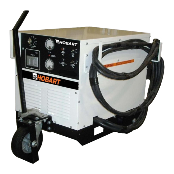
OM-2244 / Operation and Maintenance Manual DCS-600 / Series 500082 / Solid State Transformer-Rectifiers Chapter 1 Description/Operation Section 1 Description 1) General The GPU-600 Solid State Transformer-Rectifiers covered by this manual are manufactured by ITW GSE, Troy, Ohio 45373. These Transformer Rectifiers (GPUs) are designed to provide ground power for maintenance and startup of aircraft having 28-VDC electrical systems. - Page 14 OM-2244 / Operation and Maintenance Manual DCS-600 / Series 500082 / Solid State Transformer-Rectifiers 1. Mounting Base 7. Top Panel 2. Rear Wheels 8. Side Panel (Right Side Shown) 3. Front Caster 9. Cable Storage Basket [Option Only] 4. Front/Control Panel 10.
-
Page 15: Safety Features
OM-2244 / Operation and Maintenance Manual DCS-600 / Series 500082 / Solid State Transformer-Rectifiers Assembly of GPU-600 Power ELECTRICAL DATA MODEL 6T28-600CL 5T28-600CL 6T28-600CL DCS600T60208 DCS600T50380 DCS600T6O575 SPECIFICATION NUMBER DCS600S60208 DCS600T50380CE DCS600B60380 DCS600B60208 DCS600S50380CE DCS600S50380 INPUT Voltage 208 / 230 / 460... -
Page 16: Theory Of Operation
OM-2244 / Operation and Maintenance Manual DCS-600 / Series 500082 / Solid State Transformer-Rectifiers 6) Theory of Operation The GPU provides regulated 28.5V DC. Power to the GPU is provided from the local utility company, through the input contactor. The output contactor, controlled by the Output Switch, connects DC power to the load. - Page 17 OM-2244 / Operation and Maintenance Manual DCS-600 / Series 500082 / Solid State Transformer-Rectifiers 1. Front Panel 7. DC Ammeter 2. Convenience Receptacle (115 VAC Shown) 8. Input Power Light (amber) 3. Starting Current Control 9. Output Contactor Light (green) 4.
- Page 18 OM-2244 / Operation and Maintenance Manual DCS-600 / Series 500082 / Solid State Transformer-Rectifiers (6) Overload/Overvoltage Light (Figure 4 Item 6) The overload/overvoltage trip light turns on whenever one of the following system faults occur: The output voltage has exceeded 31.5 V DC. ...
- Page 19 OM-2244 / Operation and Maintenance Manual DCS-600 / Series 500082 / Solid State Transformer-Rectifiers b) Control Board ( Figure 5 Item 9) The control board mounts inside the GPU, on a steel panel behind the left side panel. This circuit board controls for the following functions: (1) Electronic Overvoltage/Overload Protection Circuit The control board turns off the power supply and turns on the DS2 red overload trip light on the...
- Page 20 OM-2244 / Operation and Maintenance Manual DCS-600 / Series 500082 / Solid State Transformer-Rectifiers CAUTION Improper connections will cause damage. Contact factory if your equipment specification information and/or voltage changeover diagram does not agree with your rated three-phase input voltage. 1.
- Page 21 OM-2244 / Operation and Maintenance Manual DCS-600 / Series 500082 / Solid State Transformer-Rectifiers 1. TP1 SCR Gate Pulse from R10 Adjustment 14. R60 Overload Limit (TP20) 2. TP2 SCR Gate Pulse from R9 Adjustment 15. R109 28 V DC Output Calibration (TP13) 3.
- Page 22 OM-2244 / Operation and Maintenance Manual DCS-600 / Series 500082 / Solid State Transformer-Rectifiers The 1 amp, F2 through F7 fuses (8, Figure 5) are located near the control board behind the left side panel. These fuses are accessible by removing the top panel. d) Control Transformer ( Figure 5 Item 6) The small control transformer located on the interior panel (7, Figure 5) provides 115 V AC to the K1 (10, Figure 5) input contactor coil, input contactor light A (12, Figure 4), and S1 (10, Figure 4) input...
- Page 23 OM-2244 / Operation and Maintenance Manual DCS-600 / Series 500082 / Solid State Transformer-Rectifiers CAUTION Capacitor charge can injure. Be sure capacitors are discharged before touching. The CR7 flyback diode (9, Figure 7) acts to facilitate discharge of the output filter circuitry as well as to protect the main SCR rectifier assembly from damaging reverse voltage spikes.
- Page 24 OM-2244 / Operation and Maintenance Manual DCS-600 / Series 500082 / Solid State Transformer-Rectifiers 3,11 1. Rectifier Heat Sink 7. Rectifier Mounting Insulator 2. SCR Mounting Clamp 8. Feedback Shunt (Not Shown) (R12) 3. Silicon Rectifier (CR1 through CR6) 9. Positive Base Silicone Diode (CR7) 4.
-
Page 25: Preparation For Use, Storage Or Shipping
OM-2244 / Operation and Maintenance Manual DCS-600/ Series 500082/ Solid State Transformer-Rectifiers Section 2 Preparation for Use, Storage, or Shipping 1) Receipt and Inspection of Equipment The GPU has been thoroughly inspected and tested at the factory and prepared for shipment in accordance with standard industrial practices for safe shipment. -
Page 26: Installation
OM-2244 / Operation and Maintenance Manual DCS-600/ Series 500082/ Solid State Transformer-Rectifiers COPPER LINE WIRE SIZE LINE RATED In Conduit In Flexible Cable VOLTS (**) No. 3 AWG No. 4 AWG No. 3 AWG No. 4 AWG No. 3 AWG No. - Page 27 OM-2244 / Operation and Maintenance Manual DCS-600/ Series 500082/ Solid State Transformer-Rectifiers b) Verify the Input Voltage Configuration The GPU may be configured for various input voltages, depending on the specific model (specification number). The factory pre-configures each unit before shipment according to the customer specifications for the input voltage.
- Page 28 OM-2244 / Operation and Maintenance Manual DCS-600/ Series 500082/ Solid State Transformer-Rectifiers If it is necessary to change the configuration, follow these steps: (1) On the T1 Changeover Board, move the jumper links as shown on the diagram for your voltage requirement.
- Page 29 OM-2244 / Operation and Maintenance Manual DCS-600/ Series 500082/ Solid State Transformer-Rectifiers (1) Make sure electrical service is off. (2) Connect the input power cables to the input power source. (3) Connect the grounding conductor to a proper ground. (4) Leave the electrical service turned off. e) Connect the Output Cable Wheel-mounted GPUs are generally shipped with the output cable already installed.
-
Page 30: Preparation For Storage
OM-2244 / Operation and Maintenance Manual DCS-600/ Series 500082/ Solid State Transformer-Rectifiers (8) Using a handheld voltmeter, verify that voltage is present at the aircraft connector. (9) Turn off the GPU. The unit is now available for regular service. 6) Preparation for Storage a) General (1) The unit should be prepared for storage as soon as possible after being removed from service. -
Page 31: Operation
OM-2244 / Operation and Maintenance Manual DCS-600/ Series 500082 / Solid State Transformer-Rectifiers Section 3 Operation IMPORTANT Before attempting to operate the converter, read this entire section to become fully familiar with how the converter operates. 1) General This section contains information for safe and efficient operation of the equipment. Operating instructions are presented in step-by-step sequence of procedures to be followed in supplying 28 V DC to an aircraft or similar load. -
Page 32: Operation Procedure
OM-2244 / Operation and Maintenance Manual DCS-600/ Series 500082 / Solid State Transformer-Rectifiers 3) Operation Procedure a) Input Control Functions (1) Turn on S1 input contactor switch (1-1, 10, Figure 4). (2) Verify that only the amber input power light (1-1, 12, Figure 4) glows. If the light glows, no problems exist requiring service. - Page 33 OM-2244 / Operation and Maintenance Manual DCS-600/ Series 500082 / Solid State Transformer-Rectifiers Chapter 2 Servicing / Troubleshooting Section 1 Troubleshooting 1) General The troubleshooting information provided in this section is limited to procedures for determining the cause of faults and for restoring the GPU to operation after faults develop which shut off the unit. Calibration, service, and repair are to be done by ITW GSE Service Department personnel, authorized distributors of ITW GSE equipment, or trained qualified electronic technicians.
-
Page 34: Troubleshooting
OM-2244 / Operation and Maintenance Manual DCS-600/ Series 500082 / Solid State Transformer-Rectifiers 2) Troubleshooting a) Description The troubleshooting chart lists information under three headings: Trouble, symptom, and condition Probable cause Test, check, and remedy a) Use of the Troubleshooting Chart The troubleshooting chart is designed to provide maintenance and repair personnel with a timesaving guide for locating the source of trouble. -
Page 35: Voltages Of Interest
OM-2244 / Operation and Maintenance Manual DCS-600/ Series 500082 / Solid State Transformer-Rectifiers 4) Voltages of Interest a) Across the secondary on all 3 phases - 66 VAC ± 10% * b) To secondary coil center tap on all phases - 33 VAC ± 10% * * The ±... - Page 36 OM-2244 / Operation and Maintenance Manual DCS-600/ Series 500082 / Solid State Transformer-Rectifiers b) Troubleshooting Shorted SCRs and Diodes WARNING Electric shock and fire can kill! Do not touch energized parts. Always turn off utility power to the unit before touching anything inside.
-
Page 37: Troubleshooting Tables
OM-2244 / Operation and Maintenance Manual DCS-600/ Series 500082 / Solid State Transformer-Rectifiers If no Oscilloscope is available: Remove all six service fuses next to the A1 PC board. Keep in mind during this test only one fuse at a time will be placed in the holder with the with fuses other removed. CAUTION ... - Page 38 OM-2244 / Operation and Maintenance Manual DCS-600/ Series 500082 / Solid State Transformer-Rectifiers 3. Line contactor chatters a. Input cables too small or too Use input cables of sufficient long capability for proper operation of the machine. Refer to Section 1-2, Figure 1 for proper cable size to be used.
- Page 39 OM-2244 / Operation and Maintenance Manual DCS-600/ Series 500082 / Solid State Transformer-Rectifiers c. Ambient temperature too high Operate at reduced loads when temperature exceeds 104° F (40° C) or improve cooling ambient. d. Ventilation blocked Check that air intake and exhaust openings are not obstructed.
- Page 40 OM-2244 / Operation and Maintenance Manual DCS-600/ Series 500082 / Solid State Transformer-Rectifiers 1. Abnormal current fluctuation, a. Loose cable connections at Check for overheated connections voltage nearly constant output and tighten. GPU Will Not Turn Off 1. Contactor fails to open a.
- Page 41 OM-2244 / Operation and Maintenance Manual DCS-600/ Series 500082 / Solid State Transformer-Rectifiers Trouble, Symptom, Condition Probable Cause Test, Check, and/or Remedy Output Voltage Not Proper Level 1. Poor voltage regulation a. Loose connection of voltage Check connection at output sensing lead contactor and control circuit board.
- Page 42 OM-2244 / Operation and Maintenance Manual DCS-600/ Series 500082 / Solid State Transformer-Rectifiers Measure voltage between + and – d. Defective output contactor (K2). terminals on K2 Coil with S1 on and S2 held in Close position. If 28.5 VDC is present K2 is defective. 2.
-
Page 43: Calibration And Test Of Pc Control Board
OM-2244 / Operation and Maintenance Manual DCS-600/ Series 500082 / Solid State Transformer-Rectifiers Section 2 Calibration and Test of PC Control Board IMPORTANT Before attempting to make tests and adjustments on the GPU, READ THIS ENTIRE SECTION to become familiar with the proper procedures. 1) General This section describes the test points, test values, and adjustment locations for testing and adjusting the printed circuit board that controls the GPU. - Page 44 OM-2244 / Operation and Maintenance Manual DCS-600/ Series 500082 / Solid State Transformer-Rectifiers Figure 2 GPU Circuit Board Components December 15, 2014 Chapter 2-2 Page 2...
- Page 45 OM-2244 / Operation and Maintenance Manual DCS-600/ Series 500082 / Solid State Transformer-Rectifiers Figure 3 GPU Circuit Board Test Points and Controls December 15, 2014 Chapter 2-2 Page 3...
- Page 46 OM-2244 / Operation and Maintenance Manual DCS-600/ Series 500082 / Solid State Transformer-Rectifiers Test Point Function Signal Controlled by: SCR Gate Pulse Phase 3 SCR Gate Pulse Phase 2 PC Board Common +10.0 VDC Timer Voltage +15 V Regulated Voltage –15 V Regulated Voltage +24 V Unregulated Voltage SCR Gate Pulse Phase 1...
-
Page 47: Test Procedure
OM-2244 / Operation and Maintenance Manual DCS-600/ Series 500082 / Solid State Transformer-Rectifiers 3) Test Procedure Follow the table steps in this section to verify that the PC board is functioning properly. If the voltage readings to the PC board common are not within specification, attempt to correct the reading by adjusting the applicable control. -
Page 48: Circuit Board Calibration
OM-2244 / Operation and Maintenance Manual DCS-600/ Series 500082 / Solid State Transformer-Rectifiers TEST TEST TEST VOLTAGE TEST STEP POINT CONDITION MEASUREMENT DESCRIPTION Checks for null (0) by R38 for the no TP14 Open circuit: no load 0 VDC ± .01V load current signal Checks voltage slope calibrated with TP17... - Page 49 OM-2244 / Operation and Maintenance Manual DCS-600/ Series 500082 / Solid State Transformer-Rectifiers Calibration Procedure Connect the output cable to the load bank. Connect a voltmeter to the output. Turn the power switch on. The amber “Power On” light should be on. Set the SCR gate balance a) Connect the oscilloscope probe to the heat sink and the oscilloscope ground to the braid of the heat sink fly-back diode (CR 7).
- Page 50 OM-2244 / Operation and Maintenance Manual DCS-600/ Series 500082 / Solid State Transformer-Rectifiers (10) Check the voltage slope adjustment a) Apply a 400 amp load. b) Connect the voltmeter positive to TP17 and negative to TP14. c) The test point voltage should be 0.000 to 0.020 VDC. d) Adjust R102 (voltage slope adjust) for proper reading.
-
Page 51: Scheduled Maintenance
OM-2244 / Operation and Maintenance Manual DCS-600/ Series 500082 / Solid State Transformer-Rectifiers Section 3 Scheduled Maintenance 1) General The ITW GSE GPU is designed to be as maintenance free as possible. Therefore, there are few maintenance requirements. Field maintenance of the GPU should be performed only by qualified service personnel, and should be limited to cleaning and inspection of the unit and its components, as well as, the replacement of lamps and fuses. -
Page 52: Inspection During Operation
OM-2244 / Operation and Maintenance Manual DCS-600/ Series 500082 / Solid State Transformer-Rectifiers 3) Inspection During Operation a) Make sure the meters are functioning. If a meter is suspected of being inaccurate, check it against a test instrument. b) Verify the lights for Input Power On and Output Contactor closed are functional. Replace if necessary. The Overload/Over Voltage light is an LED, so it will probably not fail. -
Page 53: Lubrication
OM-2244 / Operation and Maintenance Manual DCS-600/ Series 500082 / Solid State Transformer-Rectifiers h) Inspect the output contactor. If the contacts are badly burned, the contactor should be replaced as soon as possible. Slightly pitted and burned contacts can be cleaned up with a commercial contact cleaner and very fine-grained emery cloth or equivalent. -
Page 54: Inspection Records
OM-2244 / Operation and Maintenance Manual DCS-600/ Series 500082 / Solid State Transformer-Rectifiers d) Oil Locations The figure below shows a tube extending upward from the rear bearing. The front bearing has a similar tube. Use these tubes to oil the bearings. Figure 3 Fan Motor Oil Locations 7) Inspection Records Since the fan lubrication is so infrequently, you should keep track of the lubrications using the chart below... -
Page 55: Unscheduled Repair
OM-2244 / Operation and Maintenance Manual DCS-600/ Series 500082 / Solid State Transformer-Rectifiers Chapter 3 Overhaul / Major Repair / Inspection Unscheduled Repair 1) General Repair of the GPU will consist primarily of parts replacement. Most of the components used in the GPU cannot be disassembled and repaired, and must be replaced if faulty. -
Page 56: Component Removal And Replacement
OM-2244 / Operation and Maintenance Manual DCS-600/ Series 500082 / Solid State Transformer-Rectifiers Loosen the cable clamp at the base and remove the output cable from the GPU. g) If the unit is a bridge mount unit, also disconnect and remove the remote control cables. h) If the unit is bridge mount or fixed mount, attach a lifting hoist or forklift to the bottom of the GPU and remove the mounting screws or bolts that attach the GPU to its mounting. - Page 57 OM-2244 / Operation and Maintenance Manual DCS-600/ Series 500082 / Solid State Transformer-Rectifiers Two thermostat switches mount to the top of the heat sink assembly. Refer to Chapter 4-3, Figure 7. The switch on the left side controls the fan. The switch on the right side shuts down the GPU when an overload occurs.
- Page 58 OM-2244 / Operation and Maintenance Manual DCS-600/ Series 500082 / Solid State Transformer-Rectifiers SCR Diodes The six SCR diodes mount to the heat sink. If an SCR fails to conduct, it can cause excessive ripple in the output. If an SCR fails by shorting, the unit can draw excessive input current. SCR replacement is somewhat complicated, so be sure that a failed SCR is the cause of the problem before replacing.
- Page 59 OM-2244 / Operation and Maintenance Manual DCS-600/ Series 500082 / Solid State Transformer-Rectifiers Figure 2 SCR Mounting Components Figure 3 Measuring the Spring Deflection December 15, 2014 Chapter 3-1 Page 5...
- Page 60 OM-2244 / Operation and Maintenance Manual DCS-600/ Series 500082 / Solid State Transformer-Rectifiers Chapter 4-3, Figure 7 gives the part number for the diode. (1) Disconnect and remove the failed SCR diode noting how the pieces are assembled. Figure 2 shows a cross section.
-
Page 61: Introduction
OM-2244 / Operation and Maintenance Manual DCS-600/ Series 500082 / Solid State Transformer-Rectifiers Chapter 4 Illustrated Parts List Section 1 Introduction/ Numerical Index 1) General The Illustrated Parts List identifies, describes, and illustrates main assemblies, subassemblies, and detail parts of your ground power unit manufactured by ITW GSE Palmetto Florida. 2) Purpose The purpose of this list is to provide parts identification and descriptive information to maintenance and provisioning personnel for use in provisioning, requisitioning, purchasing, storing, and issuing of spare parts. - Page 62 OM-2244 / Operation and Maintenance Manual DCS-600/ Series 500082 / Solid State Transformer-Rectifiers (1) FIGURE-ITEM NO. Column This column lists the figure number of the illustration applicable to a particular parts list and also identifies each part in the list by an item number. These item numbers also appear on the illustration.
-
Page 63: Numerical Index
OM-2244 / Operation and Maintenance Manual DCS-600/ Series 500082 / Solid State Transformer-Rectifiers (5) UNITS PER ASSEMBLY Column This column indicates the quantity of parts required for an assembly or subassembly in which the part appears. This column does not necessarily reflect the total used in the complete end item. Numerical Index 6 Explanation of Numerical Index The purpose of this index is to assist the user in finding the illustration and description of a part when the... - Page 64 OM-2244 / Operation and Maintenance Manual DCS-600/ Series 500082 / Solid State Transformer-Rectifiers FIGURE – ITEM NO. FIGURE – ITEM NO. ITW GSE PART NO. ITW GSE PART NO. 288310-001 5-14 402670 288310-002 7-10 402832-003 288310-003 403091-008 288310-004 5-11 403189 288310-005 403955-017 288310-006...
- Page 65 OM-2244 / Operation and Maintenance Manual DCS-600/ Series 500082 / Solid State Transformer-Rectifiers FIGURE – ITEM NO. FIGURE – ITEM NO. ITW GSE PART NO. ITW GSE PART NO. 83B1101 W11166-009 W11166-011 3-10 W9760-066 December 15, 2014 Chapter 4-1 Page 5...
- Page 66 OM-2244 / Operation and Maintenance Manual DCS-600/ Series 500082 / Solid State Transformer-Rectifiers This page intentionally left blank. December 15, 2014 Chapter 4-1 Page 6...
- Page 67 OM-2244 / Operation and Maintenance Manual DCS-600/ Series 500075/ Solid State Transformer-Rectifiers Section 2 Manufacturer's Codes 1) Explanation of Manufacturer’s (Vendor) Code List The following list is a compilation of vendor codes with names and addresses for suppliers of purchased parts listed in this publication.
- Page 68 OM-2244 / Operation and Maintenance Manual DCS-600/ Series 500075/ Solid State Transformer-Rectifiers Vendor’s Name and Address Vendor’s Name and Address Code Code 1DL99 Fleetguard Inc. 2N562 Power Transmission Sales Inc. Div. of Cummins Engine Company 531 Washington 311 N. Park Street P.O.
- Page 69 OM-2244 / Operation and Maintenance Manual DCS-600/ Series 500075/ Solid State Transformer-Rectifiers Vendor’s Name and Address Vendor’s Name and Address Code Code 39TH9 Motion Industries Inc. 57347 Wall Industries Inc. 8580 Industry Park Dr. 5 Watson Brook Rd. Piqua, OH 45356-8535 Exeter, NH 03833-4589 40121 Peterson Mfg.
- Page 70 OM-2244 / Operation and Maintenance Manual DCS-600/ Series 500075/ Solid State Transformer-Rectifiers Vendor’s Name and Address Vendor’s Name and Address Code Code 71400 Cooper Bussmann Inc. 81703 Mulberry Metal Products Inc. 114 Old State Road 2199 Stanley Terrace Ellisville, MO 63021-5942 Union , NJ 07083-4399 72619 Dialight Corporation...
-
Page 71: Illustrated Parts List
OM-2244 / Operation and Maintenance Manual DCS-600/ Series 500082 / Solid State Transformer-Rectifiers Section 3 Illustrated Parts List 1) Explanation of Parts List Arrangement The parts list is arranged so that the illustration will appear on a left-hand page and the applicable parts list will appear on the opposite right-hand page. - Page 72 OM-2244 / Operation and Maintenance Manual DCS-600/ Series 500082 / Solid State Transformer-Rectifiers Figure 1 Final Assembly of GPU-600 Power Supply December 15, 2014 Chapter 4-3 Page 2...
- Page 73 OM-2244 / Operation and Maintenance Manual DCS-600/ Series 500082 / Solid State Transformer-Rectifiers UNITS FIGURE ITW GSE NOMENCLATURE ITEM NO. PART NO. ASSY. Base Assembly (See Figure 4) Ref. 288267 Panel, Side 288266 Panel, Top 283323 Bracket, Cable Hanger 282658 Label, Warning Clearance 402025-002 Cable, Output, 28 V , 20 ft...
- Page 74 OM-2244 / Operation and Maintenance Manual DCS-600/ Series 500082 / Solid State Transformer-Rectifiers Figure 2 Internal Components – Part 1 December 15, 2014 Chapter 4-3 Page 4...
- Page 75 OM-2244 / Operation and Maintenance Manual DCS-600/ Series 500082 / Solid State Transformer-Rectifiers UNITS FIGURE ITW GSE NOMENCLATURE ITEM NO. PART NO. ASSY. 288271 Panel, PC Board 180294B Board, PC, Control, Ay. …Spacer, Pc Board 404915-001 180480 Choke Assembly 180065 Shunt, 2000 Amp, 50 mV (for ammeter) Ref.
- Page 76 OM-2244 / Operation and Maintenance Manual DCS-600/ Series 500082 / Solid State Transformer-Rectifiers Figure 3 Internal Components – Part 2 December 15, 2014 Chapter 4-3 Page 6...
- Page 77 OM-2244 / Operation and Maintenance Manual DCS-600/ Series 500082 / Solid State Transformer-Rectifiers UNITS FIGURE ITW GSE NOMENCLATURE ITEM NO. PART NO. ASSY. Panel, Front, GPU, Ay. (See Figure 5) Ref. 405278-007 Capacitor, ALS, 115000 MF, 40 VDC A,C,F,J, (V56289, # 36DX772F200DF2A) Capacitor, ALS, 115000 MF, 40 VDC B,E,G,H,K …Insulator, Mylar, .014, 2”...
- Page 78 OM-2244 / Operation and Maintenance Manual DCS-600/ Series 500082 / Solid State Transformer-Rectifiers Figure 4 Base Assembly December 15, 2014 Chapter 4-3 Page 8...
- Page 79 OM-2244 / Operation and Maintenance Manual DCS-600/ Series 500082 / Solid State Transformer-Rectifiers UNITS FIGURE ITW GSE NOMENCLATURE ITEM NO. PART NO. ASSY. 288321-001 Base, Ay. 288321-002 Base, Ay. 288262 Base, Mounting, GPU 288282 Support, Caster, 5 Wheel …Spacer, 5 288349 Wheel 288283...
- Page 80 OM-2244 / Operation and Maintenance Manual DCS-600/ Series 500082 / Solid State Transformer-Rectifiers G P U 600 Figure 5 Front panel Assembly December 15, 2014 Chapter 4-3 Page 10...
- Page 81 OM-2244 / Operation and Maintenance Manual DCS-600/ Series 500082 / Solid State Transformer-Rectifiers UNITS FIGURE ITW GSE NOMENCLATURE ITEM NO. PART NO. ASSY. 288307-003 Panel, Front, GPU, Assembly A,C,F,J,L 288307-004 Panel, Front, GPU, Assembly B,G,K 288307-006 Panel, Front, GPU, Assembly 288307-008 Panel, Front, GPU, Assembly 288270 Panel, Front...
- Page 82 OM-2244 / Operation and Maintenance Manual DCS-600/ Series 500082 / Solid State Transformer-Rectifiers Figure 6 Interior Panel Assembly (shown with bridge mount option) December 15, 2014 Chapter 4-3 Page 12...
- Page 83 OM-2244 / Operation and Maintenance Manual DCS-600/ Series 500082 / Solid State Transformer-Rectifiers FIGURE ITW GSE UNITS PER NOMENCLATURE ITEM NO. PART NO. ASSY. 288310-001 Panel, Interior, Ay. 288310-002 Panel, Interior, Ay. B,C,G 288310-003 Panel, Interior, Ay. 288310-004 Panel, Interior, Ay. 288310-005 Panel, Interior, Ay.
- Page 84 OM-2244 / Operation and Maintenance Manual DCS-600/ Series 500082 / Solid State Transformer-Rectifiers 3,12 Figure 7 SCR Output Rectifier Assembly of GPU-600 Power Supply December 15, 2014 Chapter 4-3 Page 14...
- Page 85 OM-2244 / Operation and Maintenance Manual DCS-600/ Series 500082 / Solid State Transformer-Rectifiers UNITS FIGURE ITW GSE PART NOMENCLATURE ITEM NO. ASSY. 288305-002 Rectifier, Output, SCR Assembly GPU-600 Ref. 288277 Heat Sink, Rectifier 405140-001 Clamp, Mounting 405139 Rectifier, Silicon, Cont. 369642 Heat Sink, SCR 288304...
- Page 86 OM-2244 / Operation and Maintenance Manual DCS-600/ Series 500082 / Solid State Transformer-Rectifiers This page intentionally left blank. December 15, 2014 Chapter 4-3 Page 16...
- Page 87 OM-2244 / Operation and Maintenance Manual DCS-600/ Series 500082 / Solid State Transformer-Rectifiers Chapter 5 Manufacturer’s Literature Diagram Number Diagram Description 288326, Rev. 0 Outline, Dimensional/Installation 288367, Rev 11 Diagram, Schematic & Connection Contact ITW GSE if copies of these drawings are not with this manual. Refer to Appendix A for specific information on GPU-600 Solid State Transformer-Rectifier optional equipment.
- Page 88 OM-2244 / Operation and Maintenance Manual DCS-600/ Series 500082 / Solid State Transformer-Rectifiers This page intentionally left blank. December 15, 2014 Chapter 5-1 Page 2...
- Page 89 OM-2244 / Operation and Maintenance Manual DCS-600/ Series 500082 / Solid State Transformer-Rectifiers Appendix A Options / Features The following is a list of options/features available for the 500082, GPU-600 Solid State Transformer-Rectifier. This chart contains the description, part number, and document number of the option/feature. There is also a column to identify which option/feature is contained in this Appendix.
- Page 90 OM-2244 / Operation and Maintenance Manual DCS-600/ Series 500082 / Solid State Transformer-Rectifiers Unusual Service Conditions This information is a general guideline and cannot cover all possible conditions of equipment use. The specific local environments may be dependent upon conditions beyond the manufacturer’s control. The manufacturer should be consulted if any unusual conditions of use exist which may affect the physical condition or operation of the equipment.
- Page 91 OM-2244 / Operation and Maintenance Manual DCS-600/ Series 500082 / Solid State Transformer-Rectifiers 4) Operation with: a) Improper fuel, lubricants or coolant b) Parts or elements unauthorized by the manufacturer c) Unauthorized modifications Operation in poorly ventilated areas December 15, 2014 Appendix A Page 3...
- Page 92 OM-2244 / Operation and Maintenance Manual DCS-600/ Series 500082 / Solid State Transformer-Rectifiers This page intentionally left blank. December 15, 2014 Appendix A Page 4...