
Related Manuals for TurboChef Double Batch


Summary of Contents for TurboChef Double Batch
- Page 1 Service Manual for the turbochef double batch rapid cook oven ©2017 TurboChef Technologies, Inc.
- Page 3 For further information, call 800.90 TURBO +1 214.379.6000 Original Instructions The information contained in this manual is important for the proper installation, use, maintenance, and repair of this oven. Follow these procedures and instructions to help ensure satisfactory baking results and years of trouble-free service. Errors –...
-
Page 4: Table Of Contents
Electrical Specifications Installation Unpacking Instructions Installation Warnings - Read Before Lifting Oven Lifting and Placing the Oven Installation Near Open Heat Source Oven Restraint Kit TurboChef Connect ChefComm Pro® Date and Time Prompt Voltage Selection Ventilation Oven Maintenance Daily Maintenance... - Page 5 Options Screen Options Screen - Editing Options Screen - Cook More Options Screen - Load Menu Options Screen - VAC Setting Options Screen - Demo Mode Options Screen - Manual Cooking Options Screen - Diagnostic Mode Options Screen - F2 Bypass Settings Screen Settings Screen - Temperature Measurement Settings Screen - Phase...
- Page 6 Troubleshooting Continued... Touch Screen is Wrong Color or Fuzzy Oven Keeps Cooling Down, Warming Up, or Turning Itself Off Menu Will Not Load – USB Firmware Will Not Update Food Not Cooking Properly Steam Present During or After Cooking No Beep or Beep Too Soft Wi-Fi Menu Download Will Not Work Oven Systems and Components Controls System...
- Page 7 Oven Door Door Gasket Door Interlock Switches Filtering System Grease Filter Catalytic Converter Oven Schematics Oven Schematic Control Board and Heater Schematics Appendix – Replacing Oven Components Oven Face and Removable Cavity Components Oven Door Oven Components, Side Panel Removed Oven Components, Controls Oven Components, Back Panel Removed A-10...
- Page 8 This page intentionally left blank.
-
Page 9: Important Safety Instructions
IMPORTANT SAFETY INSTRUCTIONS WARNING: When operating this oven, strictly adhere to the following safety precautions to reduce the risk of burns, electric shock, fire, injury, damage to oven or property near oven. GENERAL SAFETY INFORMATION Read all instructions before using this appliance. ... -
Page 10: Grounding Instructions
SAFETY INSTRUCTIONS GROUNDING INSTRUCTIONS Th is appliance must be grounded. In the event of an electrical short circuit, grounding reduces the risk of electric shock by providing an escape wire for the electric current. This oven is equipped with a cord that has a grounding wire with a grounding plug, which must be plugged into an outlet that is properly installed and grounded. -
Page 11: Specifications And Installation
Specifications and Installation... -
Page 13: Theory Of Operation
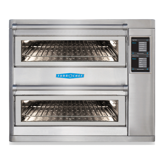
- Simple and intuitive touch controls NOTE: 5” (127 mm) side clearance is required if the - Multi-language user interface oven is placed next to another Double Batch oven. - Variable-speed High h recirculating air impingement 5 in. - Oscillating rack for high heat transfer without spotting... -
Page 14: Certifications
US/Canada: 208/240 VAC*, 60 Hz, 50 A, placed on a food station at all times. 8,320/9,600 watts TurboChef will not recognize a fallen oven as a warrantable claim and is not liable for any injuries that may result. 3 Phase Delta... -
Page 15: Lifting And Placing The Oven
Lifting and Placing the Oven Installation Near Open Heat Source 1. Prepare a surface at least 28.6” (726 mm) deep When placing a TurboChef oven near an open and capable of supporting 262 lb. (119 kg). heat source (Figure 2), strictly adhere to the following: 2. -
Page 16: Oven Restraint Kit
TurboChef Connect TurboChef Connect allows you to remotely update the menu for ovens that are connected via WiFi. TurboChef Connect also includes reporting tools and live data streams to view what is being cooked and when. You can also receive alerts via email. -
Page 17: Oven Maintenance
Oven Maintenance... -
Page 19: Daily Maintenance
The following steps will help maintain your oven. Use - TurboChef Oven Cleaner (Part Number: 103180) only TurboChef Oven Cleaner and Oven Guard. The use - TurboChef Oven Guard (Part Number: 103181) of any other cleaning products can damage critical oven - Nylon scrub pad, cleaning towel, disposable gloves, components, resulting in a non-warranty service call. - Page 20 Step 7 Step 8: Clean the Air Filter CAUTION: TurboChef does not recognize blocked air vents as a warrantable claim. The filter must be cleaned regularly or replaced if damaged. During oven operation, the filter must remain in place at all times.
-
Page 21: Weekly Maintenance
- TurboChef Oven Guard (Part Number: 103181) Use only TurboChef Oven Cleaner and Oven Guard. The - Nylon scrub pad, cleaning towel, disposable gloves, use of any other cleaning products can damage critical protective eyewear, dust mask (optional) oven components, resulting in a non-warranty service call. - Page 22 Step 8 Step 9: Clean the Air Filter CAUTION: TurboChef does not recognize blocked air vents as a warrantable claim. The filter must be cleaned regularly or replaced if damaged. During oven operation, the filter must remain in place at all times.
- Page 23 Operating the Oven...
-
Page 25: Oven Controls
NOTE: Display options vary depending on which features are enabled. Oven Controls 5. Menu Selection The oven contains 8 menus. The top oven The Double Batch’s interface allows simultaneous contains menus 1-4 and the bottom oven control over both ovens. During standard operation, contains menus 5-8. -
Page 26: Cooking
(page 12). The Double Batch oven uses impingement to create high heat transfer rates and reduce cook time. Air enters the cavity from the top and bottom and is distributed by the jetplates. Because of this design and to ensure uniformity of cooking, the top and bottom jetplates must be installed during operation. - Page 27 Step 5: Select a Group Step 8: Check/Remove Food from Oven NOTE: Touch the WARNING: Dish/ Bottom Oven Top Oven Top Oven Expand/Collapse icon to inside of oven and Group 1 access additional groups. Group 8 > Item 9 door is hot! Group 2 Cooking done, please check food.
-
Page 28: Manual Cook Mode
COOKING Manual Cook Mode Manual Cook Mode is intended for professionals, and allows cooking “on the fly,” whereas Menu Cook Mode (page 10) allows cooking from preset cook settings. Some oven versions also allow holding tempera- tures. To access Manual Cook Mode, touch the Manual icon when the oven is off or cooling down (page 11) or touch the Menu/Manual toggle on the Menu Mode screen. -
Page 29: Info Mode
Info Mode Info Mode Info Mode To access Info Mode, touch the “i” icon when both INFORMATION Serial Number: INFORMATION Cook Counter: HHDXXXXXXX 0007 ovens are off or cooling down. From the Info Mode COUNTERS Menu Version: Total Cook Time: screen (Figure 6), access: HHD-XXXX-XX OPTIONS... -
Page 30: Options Screen - Editing
INFO MODE Options Screen Options Screen - Diagnostic Mode From the options screen (Figure 12), enable/disable: Diagnostic Mode allows service technicians to view Editing and test oven components. Diagnostic Mode should Cook More be set to NO during regular operation. Load Menu Options Screen - F2 Bypass If F2 Bypass is set to YES, the oven will log an F2... -
Page 31: Settings Screen - Wifi Network
TurboChef Connect also allows If you are unsure of the WiFi Password for the net- work, contact your network administrator. In some you to receive alerts via email. -
Page 32: Settings Screen - Time
INFO MODE Settings Screen - Time Edit Mode An accurate time is necessary for ensuring the accu- Edit Mode allows the operator to: racy of diagnostics and fault condition reporting. Edit the set temperatures NOTE: The oven may not retain the time if left Edit item settings, group names, and unplugged for a prolonged period of time. - Page 33 NOTE: The sum of all events must be 100; Bottom Oven Top Oven otherwise the oven will not allow the changes to be Group 1 Group 1 saved. Group 2 Group 2 500 °F 500 °F 3. Event %Air Group 3 Group 3 Group 4 Group 4...
-
Page 34: Loading And Saving Menus
(top level) of the USB drive. 4. Name the file. NOTE: If your version of ChefComm Pro is lacking these features, contact TurboChef Customer Support to obtain an update.. Figure 20: USB Port... -
Page 35: Troubleshooting
Troubleshooting... -
Page 37: Fault Code Descriptions
Overview of Troubleshooting F6: Electrical Compartment Temperature High This fault is displayed when the electrical compart- This section contains information on the ment temperature exceeds 158 º F (70 º C), measured following: by a sensor on the control board. The electrical com- - Fault code descriptions partment temperature is monitored once per minute. -
Page 38: F1-1/F1-2: Blower
TROUBLESHOOTING Fault Code and Description When Active Refer to... Warmup Idle Cooking Service Screen F1-1/F1-2: Blower Page 21 Page 22 F2-1/F2-2: Cook Temperature Low F6: EC Temperature High Page 23 ... - Page 39 Troubleshooting: F1-1: BLOWER (Top Oven) F1-2: BLOWER (Bottom Oven) Remove obstruction Is the blower motor or if necessary, replace Do the resistance measure- spinning freely? blower motor. ments between windings and chassis agree with values on motor windings resistance Is Status Indicator “A” table (below)? backlit on the Service 1.
- Page 40 TROUBLESHOOTING Troubleshooting: F2-1: LOW TEMP (Top Oven) F2-2: LOW TEMP (Bottom Oven) Is there a defective heater? Reset and determine why Is the high-limit thermostat tripped? it tripped – excess grease 1. Isolate the heater circuits by buildup, etc. The reset disconnecting them from the button is on the back panel respective high-limit switch...
- Page 41 Troubleshooting: F6: EC TEMP (Electrical Compartment Temperature High) Does the oven have Is the oven in an area of moderate room to ventilate? temperature (120ºF (49ºC) or cooler)? (not tightly enclosed by other appliances Relocate oven to or fixtures?) Move oven to open area cooler area.
- Page 42 TROUBLESHOOTING Troubleshooting: F8-1: HEAT LOW (Top Oven) F8-2: HEAT LOW (Bottom Oven) Is the oven phase Set the proper phase Is the blower motor (Single or Multi) set type and try warming up moving air? Control the properly on the Settings the oven again.
-
Page 43: F10: Communication Failure
Troubleshooting: F10: Communication Failure Cycle power. Does the F10 reappear after approxiamately 5 seconds? Replace the comm wire between Sage Replace the I/O control Return the oven and Phoenix (red, orange, yellow, board (SAGE). If the to service. black cable). Did this resolve the problem persists, replace issue? the touch screen-display... -
Page 44: Non-Fault Code Troubleshooting
TROUBLESHOOTING Non-Fault Code Troubleshooting This section provides troubleshooting tips for issues that may occur independently of an oven fault. Troubleshooting: “Door Open” Message when Door is Closed Check the door/door Adjust/tighten the door hinge connection. Is (see Appendix for door the door loose on the assembly detail, page A-4). -
Page 45: No Display - Screen Is Blank
Troubleshooting: No Display – Screen is Blank Unplug the oven for 20 Return the oven to service. seconds and plug it back in. Did the display come back? Is the display white or does it Are any of the LEDs on have stripes across it? the back of the display lit? Replace the power... -
Page 46: Touch Screen Is Locked Up Or Unresponsive
TROUBLESHOOTING Troubleshooting: Touch Screen is Locked Up or Unresponsive Follow the “Troubleshooting: Is the problem related to Is the screen blank? No Display-Screen is Blank” specific food items? steps on Page 27. Reload the menu (page 18). Doees the oven show a door open message? Follow the “Troubleshooting: ‘Door Open’... -
Page 47: Oven Keeps Cooling Down, Warming Up, Or Turning Itself Off
Troubleshooting: Oven Keeps Cooling Down, Warming Up, or Turning Itself Off Do the door switches require Troubleshoot the fault code NO Is there a fault code present? adjustment or is the door (pages 21-25). misaligned? Replace the display. Confirm with Technical Support that the replacement display has additional shielding for EMI protection. -
Page 48: Menu Will Not Load - Usb
If it is larger for this oven. If necessary, obtain a new than 8GB, try a different USB. menu file from TurboChef. Does the Does the problem persist? problem persist? On a computer, copy and paste the... -
Page 49: Firmware Will Not Update
Does the problem persist? Obtain a new firm- ware file (directory) and/or USB drive from TurboChef Does the firmware update finish? Technical Support. Is there a big “X” and Cycle power to the oven and try the update a big checkmark on the again. -
Page 50: Food Not Cooking Properly
Is the menu part number Ensure the food item and revision correct? Verify is being properly with customer or contact stored/prepared TurboChef Customer Service. before cooking. Verify the SSR wiring Update the menu is correct (page 41), Is the correct amount (page 18). -
Page 51: Steam Present During Or After Cooking
Troubleshooting: Steam Present During or After Cooking NOTE: excessive steam may result depending on the type of food being cooked, e.g., frozen chicken wings. Perform both the daily and quarter- ly cleaning procedures (pages 5-8). Verify the ventilation holes on the rear vent catalyst housing cover are not blocked with debris. -
Page 52: Wi-Fi Menu Download Will Not Work
If (see page 15)? that begins with “00409”? the problem persists, replace the wireless module and contact TurboChef to ensure the new module is registered. Reset the store’s router. Connect Verify SSID, security type, to the router using a smart... -
Page 53: Oven Systems And Components
Oven Systems and Components... -
Page 55: Controls System
Controls System Display and UI Control Board (Phoenix) The display is the primary user interface. It is a The control system signals, senses, commands, and 7-inch capacative touch screen with a tempered pro- actuates all electrical components within the oven. tective glass cover. -
Page 56: Relays, K1, K2, K3, & K4
Thermostat, Cooling Fan TurboChef Connect. The oven logs events such The cooling fan thermostat actuates the rear cool- as cook cycles and faults to TurboChef Connect, and menu updates can be pushed via TurboChef ing fans when the electrical compartment Connect to one or many ovens simultaneously. -
Page 57: Convection System
Different hole patterns are clean, and recirculate air into the cook cavity. See available for custom cooking results; contact page 41 for a schematic. TurboChef for more details. The convection system consists of the following Jetplate Support Rails components: Each jetplate is supported by two rails. -
Page 58: Oven Door
OVEN SYSTEMSAND COMPONENTS Oven Door The oven door consists of the following components: Door Gasket Door Interlock Switch Door Gasket The door gasket ensures a proper seal when the door is closed. CAUTION: Do not scrub the gasket or attempt to scrape beneath it. -
Page 59: Filtering System
Catalytic Converter Filtering System The catalytic converter, a VOC type catalyst, is The filtering system consists of the following located behind the rear cook cavity wall and is components: responsible for cleaning the recirculating airflow. Grease filter The catalyst functions by substantially lowering ... - Page 60 OVEN SYSTEMSAND COMPONENTS This page intentionally left blank.
- Page 61 Schematics...
- Page 63 GREEN W HITE G REEN BLACK W HITE BLACK JUM PER Figure 22: Oven Schematic...
-
Page 64: Oven Schematics
OVEN SCHEMATIC RED - VDC OUTPUT ELEMENT LAYOUT WHITE - CONTROL OUTPUT BLACK - GROUND ORANGE - STATUS OUTPUT HX 1 TOP OVEN HX 2 SAGE CONTROL BOARD BOT OVEN HX 3 HX 4 PHOENIX J13 RED - VDC OUTPUT J1 - "A"... -
Page 65: Appendix - Replacing Oven Components
Appendix - Replacing Oven Components... - Page 67 - Oven Components, Controls (pages A-8 through A-9) - Oven Components, Back Panel Removed (A-10 through A-11) If you have any questions that are not addressed in this manual or appendix, please contact TurboChef Customer Service at 800.90TURBO or +1 214.379.6000.
- Page 68 HHD-3002 Jetplate, Top (Kit) Screw, Wing Head, Fast Lead, SS Included with Kit (qty 1 per cavity) Fast Lead Screw Retainer Logo, TurboChef HHC-6336 Nut, Push 1/8 Dia, Tinnerman 101293 (qty 2) Panel, Front HHD-8384 Screw 8-32 X 3/8 PFLH, 100 Deg, SS...
- Page 69 Oven Face and Removable Cavity Parts, Continued WARNING: Before removing any oven part, be sure the oven has completed “cooling down” (see “Step 10” on page 11) and is removed from the power source. Some components removed for clarity. Figure Item Description Item Part Number Fastener Description...
-
Page 70: Oven Door
APPENDIX - REPLACING OVEN COMPONENTS Oven Door WARNING: Before removing any oven part, be sure the oven has completed “cooling down” (see “Step 10” on page 11) and is removed from the power source. - Page 71 Figure Item Description Item Part Number Fastener Description Fastener Part Number(s) Reference # 105047 Bumper, Round (qty 2 per door) HHD-8377 Door Kit (Glass/Frame) Screw, 6-32 X .38 PFH 100 Deg, SS 101430 (qty 8 per door) (qty 1 per door) HHD-8236 Gasket, Door (qty 1 per door)
-
Page 72: Oven Components, Side Panel Removed
APPENDIX - REPLACING OVEN COMPONENTS Oven Components, Side Panels Removed WARNING: Before removing any oven part, be sure the oven has completed “cooling down” (see “Step 10” on page 11) and is removed from the power source. 10 11 12 13 x2 (x3, DL Configs) x3, DL Configs... - Page 73 Figure Item Description Item Part Number Fastener Description Fastener Part Number(s) Reference # 100539 EMI Filter Screw, #8 X 1/2 Phil., Truss, Type 17, Serr, SS 101688 (qty 2 each) (qty 1 per cavity) DL Config: 103566 (qty 2) Fuse Block Nut #6-32 Keps External Tooth SS 102961 All Others: 103548 (qty 2)
-
Page 74: Oven Components, Controls
APPENDIX - REPLACING OVEN COMPONENTS Oven Components, Controls WARNING: Before removing any oven part, be sure the oven has completed “cooling down” (see “Step 10” on page 11) and is removed from the power source. - Page 75 Figure Item Description Item Part Number Fastener Description Fastener Part Number(s) Reference # Gasket, Display HHD-8447 Screw, #6-32 x 1/4, SIM, Int Tooth, PPHD 102910 (qty 4) Nut #6-32 Keps External Tooth SS 102961 (qty 4) SAGE Control Board, Kit CON-3019-2 Bracket, Control Board Mounting, Top HHD-8493...
-
Page 76: Oven Components, Back Panel Removed
A-10 APPENDIX - REPLACING OVEN COMPONENTS Oven Components, Back Panel Removed WARNING: Before removing any oven part, be sure the oven has completed “cooling down” (see “Step 10” on page 11) and is removed from the power source. - Page 77 A-11 Figure Item Description Item Part Number Fastener Description Fastener Part Number(s) Reference # Air Filter HHD-8422 HHB-8106 Blower Motor Nut, 1/4-20, Serrated Hex Flange, Zinc 100906 (qty 5 each) (qty 1 per cavity) CON-7013 Screw, #8 X 1/2 Phil., Truss, Type 17, Serr, SS 101688 (qty 2 each) Blower Motor Speed Controller (qty 1 per cavity)
- Page 78 For service or information: wi thin n o r th ame r i c a c al l Customer Support at 800.90 T U R B O ou ts id e n o r th a me r ic a c al l +1 214.379.6000 or Your Authorized Distributor Global Operations Customer Support...