
Related Manuals for Omron SYSMAC NX-CIF Series


Summary of Contents for Omron SYSMAC NX-CIF Series
- Page 1 Machine Automation Controller NX-series Communications Interface Units User’s Manual NX-CIF Communications Interface Units W540-E1-07...
- Page 2 No patent liability is assumed with respect to the use of the information contained herein. Moreover, because OMRON is constantly striving to improve its high-quality products, the information contained in this manual is subject to change without notice. Every precaution has been taken in the preparation of this manual. Neverthe- less, OMRON assumes no responsibility for errors or omissions.
-
Page 3: Introduction
Introduction Introduction Thank you for purchasing an NX-series Communications Interface Unit. This manual contains information that is necessary to use the NX-series Communications Interface Units. Please read this manual and make sure you understand the functionality and performance of the NX-series Communications Interface Unit before you attempt to use it in a control system. -
Page 4: Table Of Contents
CONTENTS CONTENTS Introduction ......................1 Intended Audience............................1 Applicable Products ............................. 1 Relevant Manuals ..................... 6 Manual Structure ...................... 7 Page Structure and Icons ..........................7 Special Information ............................8 Precautions on Terminology ........................8 Terms and Conditions Agreement................ 10 Warranty, Limitations of Liability ........................ - Page 5 CONTENTS Section 2 Specifications and Application Procedures Specifications ........................2-2 2-1-1 General Specifications........................ 2-2 2-1-2 Specifications of Individual Units ....................2-3 Application Procedures ......................2-5 Section 3 Part Names and Functions Part Names..........................3-2 3-1-1 NX-CIF101 and NX-CIF105......................3-2 3-1-2 NX-CIF210..........................
- Page 6 CONTENTS 7-3-1 Input Notification Data and Output Notification Data..............7-6 7-3-2 SIDs and SID Responses ......................7-7 7-3-3 Input Data Type and Output Data Type ..................7-10 7-3-4 Send Completed Toggle Bit ...................... 7-10 Examples of Communications between CPU Unit or Communications Master and CIF Unit..........................
- Page 7 CONTENTS 10-1 Cleaning and Inspections ....................10-2 10-1-1 Cleaning............................ 10-2 10-1-2 Periodic Inspection ........................10-2 10-2 Maintenance Procedures ....................10-5 Appendices A-1 Dimensions ..........................A-2 A-1-1 NX-CIF101 and NX-CIF105......................A-2 A-1-2 NX-CIF210..........................A-2 A-2 Changing NX Objects from a User Program ...............A-4 A-2-1 NX Objects That You Can Change.....................
-
Page 8: Relevant Manuals
Relevant Manuals Relevant Manuals The table below provides the relevant manuals for the NX-series Communications Interface Units. Read all of the manuals that are relevant to your system configuration and application to make the most of the NX-series Communications Interface Units. Other manuals, such as related product manuals, are necessary for specific system configurations and applications. -
Page 9: Manual Structure
Manual Structure Manual Structure Page Structure and Icons The following page structure and icons are used in this manual. Level 1 heading 4 Installation and Wiring Level 2 heading Level 3 heading Mounting Units Level 2 heading Gives the current headings. -
Page 10: Special Information
Manual Structure Special Information Special information in this manual is classified as follows: Precautions for Safe Use Precautions on what to do and what not to do to ensure safe usage of the product. Precautions for Correct Use Precautions on what to do and what not to do to ensure proper operation and performance. Additional Information Additional information to read as required. - Page 11 Manual Structure • This user's manual refers to the built-in EtherCAT port on an NJ/NX-series Controller or NY-series Industrial PC as simply a built-in EtherCAT port. • This user's manual may omit manual names and manual numbers in places that refer to the user's manuals for CPU Units and Industrial PCs.
-
Page 12: Terms And Conditions Agreement
Omron’s exclusive warranty is that the Products will be free from defects in materials and workman- ship for a period of twelve months from the date of sale by Omron (or such other period expressed in writing by Omron). Omron disclaims all other warranties, express or implied. -
Page 13: Application Considerations
Disclaimers Performance Data Data presented in Omron Company websites, catalogs and other materials is provided as a guide for the user in determining suitability and does not constitute a warranty. It may represent the result of Omron’s test conditions, and the user must correlate it to actual application requirements. Actual perfor- mance is subject to the Omron’s Warranty and Limitations of Liability. -
Page 14: Safety Precautions
Safety Precautions Safety Precautions Definition of Precautionary Information The following notation is used in this manual to provide precautions required to ensure safe usage of an NX-series Communications Interface Unit. The safety precautions that are provided are extremely important to safety. Always read and heed the information provided in all safety precautions. - Page 15 Safety Precautions Warning WARNING During Power Supply Do not touch the terminal section while power is ON. Electric shock may occur. Do not attempt to take any Unit apart. In particular, high-voltage parts are present in Units that supply power while power is sup- plied or immediately after power is turned OFF.
- Page 16 Safety Precautions Voltage and Current Inputs Make sure that the voltages and currents that are input to the Units and slaves are within the specified ranges. Inputting voltages or currents that are outside of the specified ranges may cause accidents or fire.
- Page 17 Safety Precautions Online Editing Execute online editing only after confirming that no adverse effects will be caused by devia- tions in the timing of I/O. If you perform online editing, the task execution time may exceed the task period, I/O may not be refreshed with external devices, input signals may not be read, and output timing may change.
-
Page 18: Precautions For Safe Use
Precautions for Safe Use Precautions for Safe Use Transporting • When transporting any Unit, use the special packing box for it. Also, do not subject the Unit to excessive vibration or shock during transportation. • Do not drop any Unit or subject it to abnormal vibration or shock. Doing so may result in Unit malfunction or burning. - Page 19 Precautions for Safe Use • Do not write on an NX Unit with ink within the restricted region that is shown in the following figure. Also do not get this area dirty. When the Unit is installed or removed, ink or dirt may adhere to the pins in the NX bus connector, which may result in malfunctions in the CPU Rack or the Slave Termi- nal.
- Page 20 Precautions for Safe Use • Do not press the flat-blade screwdriver straight into the release holes on a screwless clamping termi- nal block. Doing so may break the terminal block. • When you insert a flat-blade screwdriver into a release hole on a screwless clamping terminal block, press it down with a force of 30N or less.
- Page 21 Precautions for Safe Use Actual Operation • Before you start operation, always register the NX Units that are connected to the Communications Coupler Unit in the host communications master as the Unit configuration information. • Check the user program, data, and parameter settings for proper execution before you use them for actual operation.
- Page 22 Precautions for Safe Use Using Communications Interface Units • Always check polarity before connecting RS-422A/485 cables. The polarity of the SDA/SDB and RDA/RDB terminals and signals are reversed for some remote devices. NX-series Communications Interface Units User’s Manual (W540)
-
Page 23: Precautions For Correct Use
Precautions for Correct Use Precautions for Correct Use Storage, Mounting, and Wiring • Follow the instructions in this manual to correctly perform installation and wiring. • Do not operate or store the Units in the following locations. Doing so may result in malfunction, in operation stopping, or in burning. - Page 24 Precautions for Correct Use Transferring Data Before you transfer the communications settings to the Unit, confirm that the controlled system will not be adversely affected. Actual Operation • If you change the event level of an error, the output status when the error occurs may also change. Confirm safety before you change an event level.
-
Page 25: Regulations And Standards
Concepts EMC Directives OMRON devices that comply with EU Directives also conform to the related EMC standards so that they can be more easily built into other devices or the overall machine. The actual products have been checked for conformity to EMC standards.*1 Whether the products conform to the standards in the system used by the customer, however, must be checked by the customer. -
Page 26: Conformance To Ul And Csa Standards
NX-series product must also comply with the standards, consult with your OMRON representative. Application conditions are defined according to the installation location. Application may not be possible for some installation locations. -
Page 27: Unit Versions
Unit Versions Unit Versions This section describes the notation that is used for unit versions, the confirmation method for unit ver- sions, and the relationship between unit versions and Support Software versions. Unit Versions A “unit version” has been introduced to manage the Units in the NX Series according to differences in functionality accompanying Unit upgrades. -
Page 28: Unit Versions And Support Software Versions
Gives the unit version of the Unit. Lot number Gives the lot number of the Unit. DDMYY: Lot number, : Used by OMRON. “M” gives the month (1 to 9: January to September, X: October, Y: November, Z: December) The following information is provided in the notched area on the Unit. -
Page 29: Related Manuals
Related Manuals Related Manuals The following manuals are related. Use these manuals for reference. Manual name Cat. No. Model numbers Application Description NX-series W540 NX-CIF Learning how to The hardware, setup methods, and Communications Interface use NX-series functions of the NX-series Communi- Units User's Manual Communications cations Interface Unit are described. -
Page 30: Specifications
Related Manuals Manual name Cat. No. Model numbers Application Description NX-series EtherNet/IP W536 NX-EIC202 Leaning how to The following items are described: Coupler Unit User's Man- use an NX-series the overall system and configuration EtherNet/IP Cou- methods of an EtherNet/IP Slave pler Unit and Eth- Terminal (which consists of an erNet/IP Slave... - Page 31 Related Manuals Manual name Cat. No. Model numbers Application Description NJ-series CPU Unit W500 NJ501- Learning the basic An introduction to the entire Hardware User’s Manual specifications of NJ-series system is provided along NJ301- the NJ-series CPU with the following information on the NJ101-...
- Page 32 Related Manuals Manual name Cat. No. Model numbers Application Description NJ/NX-series CPU Unit W505 NX701- Using the built-in Information on the built-in EtherCAT Built-in EtherCAT Port EtherCAT port on port is provided. NJ501- User’s Manual an NJ/NX-series This manual provides an introduction NJ301-...
-
Page 33: Terminology
Terminology Terminology Abbre- Term Description viation application layer status, AL status Status for indicating information on errors that occur in an application on a slave. CAN application protocol over Ether- A CAN application protocol service implemented on EtherCAT. CAN in Automation CiA is the international users' and manufacturers' group that develops and supports higher-layer protocols. - Page 34 Terminology Abbre- Term Description viation no-protocol communications With no-protocol communications, data is sent and received without any conversions. Communications protocols to perform retry processing, data type conversion processing, branch processing according to the receive data, and other processing are not used. NX bus The NX-series internal bus.
-
Page 35: Revision History
Revision History Revision History A manual revision code appears as a suffix to the catalog number on the front and back covers of the manual. W540-E1-07 Cat. No. Revision code Revision code Date Revised content February 2015 Original production April 2016 Made changes accompanying the addition of the NX-series CPU Unit and the instructions. - Page 36 Revision History NX-series Communications Interface Units User’s Manual (W540)
-
Page 37: Sections In This Manual
Sections in this Manual Sections in this Manual Maintenance and Features and System Inspections Configuration Specifications and Appendices Application Procedures Part Names and Index Functions Installation and Wiring I/O Data Specifications Unit Settings Serial Communications Serial Line Monitor Troubleshooting NX-series Communications Interface Units User’s Manual (W540) - Page 38 Sections in this Manual NX-series Communications Interface Units User’s Manual (W540)
-
Page 39: Features And System Configuration
Features and System Configura- tion This section describes the features of the Communications Interface Units and the sys- tem configuration in which the Communications Interface Units are used. 1-1 Features of Communications Interface Units ..... . . 1-2 1-2 System Configuration . -
Page 40: Features Of Communications Interface Units
The CIF Units are classified as Sysmac devices. Sysmac device is a generic name for EtherCAT slaves, EtherNet/IP slaves, and other OMRON control components that were designed with the same communications and user interface specifications. You can use Sysmac devices together with NJNX-series Machine Automation Controllers and the Support Software to achieve optimum func- tionality and ease of operation. -
Page 41: System Configuration
1 Features and System Configuration System Configuration CIF Units can be connected to the following Units. • NX-series CPU Units • NX-series Communications Coupler Units This section describes the system configuration for each type of Unit that a CIF Unit can be connected 1-2-1 System Configuration with CIF Unit Connected to CPU Unit The following figure shows a system configuration when a group of NX Units is connected to an... - Page 42 1 Features and System Configuration Letter Item Description NX-series CPU Unit This is the central control Unit in the Machine Automation Controller. It exe- cutes tasks and performs I/O refreshing and other processing for other Units and slaves. NX Units can be connected to the NX1P2 CPU Units. The NX Units perform I/O processing with connected external devices.
-
Page 43: System Configuration Of Slave Terminals
1 Features and System Configuration 1-2-2 System Configuration of Slave Terminals Slave Terminal is a generic name for a building-block remote I/O slave that contains a group of NX Units connected to a Communications Coupler Unit. The NX Units can be flexibly combined with a Communications Coupler Unit to achieve the optimum remote I/O slave for the application with less wiring, less work, and less space. - Page 44 *2. For whether an NX Unit can be connected to the Communications Coupler Unit, refer to the version information in the user’s manual for the NX Unit. *3. The term Support Software indicates software that is provided by OMRON. If you connect to a master from another company, use the software tool corresponding to that master.
-
Page 45: Unit Models, Functions, And Support Software
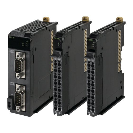
1 Features and System Configuration Unit Models, Functions, and Support Software The following three models of CIF Units are available. They have different serial interfaces, connec- tions, and numbers of serial ports. 1-3-1 Unit Model Numbers The following three models of CIF Unit are available. They have different serial interfaces, connections, and numbers of serial ports. -
Page 46: Serial Communications Instructions For The Cif Units
1 Features and System Configuration Serial Communications Instructions for the CIF Units You can use serial communications instructions for CIF Units to easily implement no-protocol data transfers and execute Modbus-RTU commands. 1-4-1 Serial Communications Instructions for CIF Units The following serial communications instructions for CIF Units are supported. Refer to the instructions reference manual for the connected CPU Unit or Industrial PC for instructions specifications. - Page 47 1 Features and System Configuration System Communications Communications Coupler Usability configuration master Unit Slave Terminal • NJ/NX-series CPU EtherCAT Coupler Unit Usable Unit EtherNet/IP Coupler Unit Not usable • NY-series Industrial CS/CJ/CP-series CPU EtherNet/IP Coupler Unit Not usable Unit Master from another EtherCAT Coupler Unit Not usable manufacturer...
- Page 48 1 Features and System Configuration 1 - 10 NX-series Communications Interface Units User’s Manual (W540)
- Page 49 Specifications and Application Procedures This section provides the general specifications and individual Unit specifications, and describes how to use the CIF Units. 2-1 Specifications ..........2-2 2-1-1 General Specifications .
-
Page 50: Specifications
Listed (UL508), ANSI/ISA 12.12.01, EU: EN 61131-2, RCM, Applicable standards and KC: KC Registration *1. Refer to the OMRON website (http://www.ia.omron.com/) or consult your OMRON representative for the most recent applicable standards for each model. 2 - 2 NX-series Communications Interface Units User’s Manual (W540) -
Page 51: Specifications Of Individual Units
2 Specifications and Application Procedures 2-1-2 Specifications of Individual Units The following table gives the specifications of individual CIF Units. Item NX-CIF101 NX-CIF105 NX-CIF210 Number of ports Serial interface RS-232C RS-422A/485 RS-232C Communications protocol No-protocol Communi- Communications method Full duplex Half duplex for Full duplex cations... - Page 52 2 Specifications and Application Procedures Item NX-CIF101 NX-CIF105 NX-CIF210 Current consumption from I/O power sup- No I/O power supply Installation Connected to CPU Unit Installation orientation: Upright Orientation Restrictions: No restrictions Connected to Communica- Installation orientation: 6 possible orientations Restric- tions Coupler Unit Restrictions: No restrictions tions...
-
Page 53: Application Procedures
2 Specifications and Application Procedures Application Procedures The following table gives the application procedures of the CIF Units. Procedure Item Description Reference Creating the Unit The CIF Unit is registered on the Support Soft- Section 5 I/O Data Settings ware. Specifications The Unit settings of the CIF Unit are made offline. - Page 54 2 Specifications and Application Procedures 2 - 6 NX-series Communications Interface Units User’s Manual (W540)
- Page 55 Part Names and Functions This section gives the names of the parts of the CIF Units and describes the functions of the parts. 3-1 Part Names ........... 3-2 3-1-1 NX-CIF101 and NX-CIF105 .
-
Page 56: Part Names
Unit Parts Letter Name Description Marker attachment loca- This is where the markers are attached. OMRON markers are pre-installed at tion the factory. You can also install commercially available markers. NX bus connector This connector is used to connect each Unit. - Page 57 3 Part Names and Functions Terminal Block The model number of the screwless clamping terminal block is NX-TBC162. Letter Name Description Terminal number The terminal numbers are given by column letters A and B, and row numbers 1 indication to 8. The combination of the column and row gives the terminal numbers from A1 to A8 and B1 to B8.
-
Page 58: Nx-Cif210
This section gives the names of the parts of the NX-CIF210, and describes the functions of the parts. Letter Name Description Marker attachment loca- This is where the markers are attached. OMRON markers are tion pre-installed at the factory. You can also install commercially available markers. NX bus connector This connector is used to connect each Unit. -
Page 59: Indicators
3 Part Names and Functions Indicators A CIF Unit has indicators that show information such as the current operating status of the Unit or sig- nal I/O status. This section gives the names of the parts of the indicators, and describes the functions of the indicators. -
Page 60: Ts Indicator
3 Part Names and Functions 3-2-1 TS Indicator The TS indicator shows the current status of the CIF Unit and the communications status with the CPU Unit or Communications Coupler Unit. The following table lists the possible states for this indicator and what they mean. Color Status Description... -
Page 61: Send/Receive Indicators
3 Part Names and Functions 3-2-2 Send/Receive Indicators These indicators show the communications status with the serial communications device. The following table lists the possible states for these indicators and what they mean. Color Status Send/receive status Indicator Yellow Sending data Not lit Waiting to send data Yellow... - Page 62 3 Part Names and Functions Change in the Position of Printed Codes NX-CIF101 and NX-CIF105 are applicable. The position of the printed codes for the SD and RD indicators has been changed from the left side to the right side of the corresponding light-emitting parts. See below.
-
Page 63: Installation And Wiring
Installation and Wiring This section describes how to install the CIF Units, how to wire the power supplies used in the NX Units, and how to wire the CIF Units. 4-1 Installing NX Units ..........4-2 4-2 Connecting the Power Supply and Ground Wires . -
Page 64: Installing Nx Units
4 Installation and Wiring Installing NX Units Refer to the section on installation in the user’s manual for the connected CPU Unit or Communications Coupler Unit for information on installing NX Units, including CIF Units. 4 - 2 NX-series Communications Interface Units User’s Manual (W540) -
Page 65: Connecting The Power Supply And Ground Wires
4 Installation and Wiring Connecting the Power Supply and Ground Wires If the CIF Unit is connected to the CPU Unit, refer to the section on wiring in the hardware user’s man- ual for the connected CPU Unit for information on wiring the power supply and ground. If the CIF Unit is connected to a Communications Coupler Unit, refer to the section on wiring in the manual for the connected Communications Coupler Unit for information on wiring the power supply and ground. -
Page 66: Wiring The Terminals
4 Installation and Wiring Wiring the Terminals This section describes how to wire the terminals on the CIF Units. Be sure that all terminal screws and cable connector screws are tightened to the torque specified in the relevant manuals. The loose screws may result in fire or malfunction. WARNING Make sure that the voltages and currents that are input to the Units and slaves are within the speci- fied ranges. - Page 67 4 Installation and Wiring Applicable Wires The wires that you can connect to the screwless clamping terminal block are twisted wires, solid wires, and ferrules that are attached to the twisted wires. The following section describes the dimensions and processed methods for applicable wires. ...
- Page 68 4 Installation and Wiring Using Ferrules If you use ferrules, attach the twisted wires to them. Observe the application instructions for your ferrules for the wire stripping length when attaching fer- rules. Always use plated one-pin ferrules. Do not use unplated ferrules or two-pin ferrules. The applicable ferrules, wires, and crimping tools are listed in the following table.
- Page 69 4 Installation and Wiring Using Twisted Wires/Solid Wires If you use twisted wires or solid wires, use the following table to determine the correct wire specifica- tions. Wire type Conductor length Terminals Twisted wires Solid wire Wire size (stripping length) Plated Unplated Plated...
- Page 70 4 Installation and Wiring Connecting/Removing Wires This section describes how to connect and remove wires. Terminal Block Parts and Names Release hole Terminal hole Required Tools Use a flat-blade screwdriver to connect and remove wires. Use the following flat-blade screwdriver. Side view Front view 8 to 12°...
- Page 71 4 Installation and Wiring Connecting Ferrules Insert the ferrule straight into the terminal hole. It is not necessary to press a flat-blade screwdriver into the release hole. Ferrule After you make a connection, make sure that the ferrule is securely connected to the terminal block. ...
- Page 72 4 Installation and Wiring Leave the flat-blade screwdriver pressed into the release hole and insert the twisted wire or the solid wire into the terminal hole. Insert the twisted wire or the solid wire until the stripped portion is no longer visible to prevent shorting.
- Page 73 4 Installation and Wiring Securing Wires You can secure the wires to the screwless clamping terminal block. Prepare a cable tie. A cable tie can be used with a width of 4 mm or less and a thickness of 1.5 mm or less. Select a cable tie correctly for the operating environment.
- Page 74 4 Installation and Wiring Bundle the wires with a cable tie and secure them to the screwless clamping terminal block. Secure wires within the range of 30 mm from the screwless clamping terminal block. 30 mm 4 - 12 NX-series Communications Interface Units User’s Manual (W540)
- Page 75 4 Installation and Wiring Removing Wires Use the following procedure to remove the wires from the terminal block. The removal method is the same for ferrules, twisted wires, and solid wires. If wires are secured firmly to the terminal block, release them first. Press the flat-blade screwdriver diagonally into the release hole.
- Page 76 4 Installation and Wiring Precautions for Safe Use • Do not press the flat-blade screwdriver straight into the release hole. Doing so may break the terminal block. • When you insert a flat-blade screwdriver into a release hole, press it down with a force of 30 N max.
- Page 77 4 Installation and Wiring Removing a Terminal Block Press the lock lever on the terminal block and pull out the top of the terminal block to remove it. Lock lever Terminal block Attaching a Terminal Block Mount the terminal block hook on the guide at the bottom of the NX Unit, lift up the terminal block, and press in on the top of the terminal block until you hear it engage.
- Page 78 4 Installation and Wiring Preventing Incorrect Attachment of Terminal Blocks In order to prevent unintentionally installing the wrong terminal block, you can limit the combination of a Unit and a terminal block. Insert three Coding Pins (NX-AUX02) into three of the six incorrect attachment prevention holes on the Unit and on the terminal block.
- Page 79 1 through 6 in the figure below. As shown in the following table, there are 20 unique pin patterns that can be used. Terminal block Unit Holes used by Holes used by OMRON OMRON Holes for incorrect Holes for incorrect attachment prevention attachment prevention...
- Page 80 Precautions for Correct Use • OMRON uses the holes other than No. 1 to 6 in the figure on the previous page. If you insert a Coding Pin into one of the holes used by OMRON on the terminal block side, this makes it impossible to mount the terminal block on a Unit.
-
Page 81: Wiring The D-Sub Connector
Wiring part Specifications Recommended products Wires Shielded twisted-pair cable Size: AWG28 to AWG22 (0.08 to 0.34 mm D-Sub 9-pin socket OMRON connector Hood: XM2S-0913 (9-pin, inch screws) Socket: XM3D-0921 (9-pin) 4 - 19 NX-series Communications Interface Units User’s Manual (W540) -
Page 82: Wiring Communications
4 Installation and Wiring Wiring Communications This section describes how to wire a CIF Unit to perform communications with an external serial com- munications device. 4-4-1 Terminal Arrangement NX-CIF101 Terminal Arrangement The terminal arrangement of the NX-CIF101 is given below. Terminal Terminal Abbrev. - Page 83 4 Installation and Wiring NX-CIF105 Terminal Arrangement The terminal arrangement of the NX-CIF105 is given below. Terminal Terminal Abbrev. Signal name Abbrev. Signal name SDA- Send data - Output SDB+ Send data + Output SDA- Send data - Output SDB+ Send data + Output TER...
- Page 84 4 Installation and Wiring Arrangement of D-sub Connector Pins on NX-CIF210 The arrangement of the D-sub connector pins on the NX-CIF210 are given in the following table. Pin No. Abbrev. Signal name Not used. Receive data Input Send data Output Data terminal ready Output Signal ground...
-
Page 85: Connecting To Serial Communications Devices
4 Installation and Wiring 4-4-2 Connecting to Serial Communications Devices You can use the following connection forms to connect a CIF Unit to one or more serial communications devices. Model number Connection form NX-CIF101 or NX-CIF210 Serial communications CIF Unit device RS-232C NX-CIF105... - Page 86 4 Installation and Wiring Connection Examples to a Host Computer RS-232C connector RS-232C connector on host computer on host computer NX-CIF101 NX-CIF210 Shield Shield Terminal No. Signal Pin No. Signal Pin No. Signal Pin No. Signal SHLD Shell SHLD NX-CIF101 NX-CIF210 ...
- Page 87 4 Installation and Wiring RS-232C 25-pin connector RS-232C 9-pin connector on host computer on host computer NX-CIF210 NX-CIF210 Pin No. Signal Pin No. Signal Shield Shield Pin No. Signal Pin No. Signal Shell SHLD Shell SHLD NX-CIF210 Connection Examples to Modems NX-CIF101 NX-CIF210 Modem...
- Page 88 4 Installation and Wiring Examples of 1:1 Connections to an RS-422A/485 Port Two-wire serial Four-wire serial communications device communications device NX-CIF105 NX-CIF105 Shield Shield Signal Signal Terminal No. Signal Terminal No. Signal A(-) RDA(-) SDA- SDA- B(+) RDB(+) SDB+ SDB+ RDA- RDA- SDA(-)
-
Page 89: Examples Of Recommended Rs-232C And Rs-422A/485 Wiring
4 Installation and Wiring 4-4-3 Examples of Recommended RS-232C and RS-422A/485 Wiring This section provides examples of the recommended RS-232C and RS-422A/485 wiring. Examples of Recommended RS-232C Wiring We recommend the following wiring for RS-232C communications, particularly in environments where noise is common. - Page 90 4 Installation and Wiring Connection examples are given in the following figures. Two-wire Connections Serial communications device NX-CIF105 Serial communications device Signal Signal Terminal No. Signal A(-) SDA- A(-) B(+) SDB+ B(+) RDA- Shield Shield RDB+ Terminating Terminating TERSDA- resistance resistance TERSDB+...
- Page 91 4 Installation and Wiring Four-wire Connections with One Transmitting Node and N Receiving Nodes Terminating Terminating resistance resistance Serial communications Serial communications device device NX-CIF105 Signal Signal Terminal No. Signal RDA(-) RDA(-) SDA- RDB(+) RDB(+) SDB+ SDA(-) SDA(-) RDA- SDB(+) SDB(+) RDB+...
- Page 92 4 Installation and Wiring 4 - 30 NX-series Communications Interface Units User’s Manual (W540)
-
Page 93: I/O Data Specifications
I/O Data Specifications This section describes the data that you can set for I/O allocations. 5-1 I/O Data Specifications for NX-CIF101 and NX-CIF105 ....5-2 5-2 I/O Data Specifications for NX-CIF210 . - Page 94 5 I/O Data Specifications I/O Data Specifications for NX-CIF101 and NX-CIF105 All of the data that you can set for the I/O allocations of the NX-CIF101 and NX-CIF105 on the Support Software correspond to NX objects. The following table shows the correspondence between I/O entry names and NX object names.
-
Page 95: I/O Data Specifications For Nx-Cif210
5 I/O Data Specifications I/O Data Specifications for NX-CIF210 All of the data that you can set for the I/O allocations of the NX-CIF210 on the Support Software corre- spond to NX objects. The following table shows the correspondence between I/O entry names and NX object names. - Page 96 5 I/O Data Specifications 5 - 4 NX-series Communications Interface Units User’s Manual (W540)
-
Page 97: Unit Settings
Unit Settings This section describes the Unit operation settings and how to set divided data sizes for CIF Units. 6-1 Unit Operation Settings ......... 6-2 6-1-1 Communications Specifications . -
Page 98: Unit Operation Settings
6 Unit Settings Unit Operation Settings The following operation settings are made for a CIF Unit from the Support Software. • Communications specifications • Transmission buffering • Event levels 6-1-1 Communications Specifications You must set the communications specifications for the ports on the CIF Units. Refer to 2-1-2 Specifica- tions of Individual Units on page 2-3 for the items to set and the setting ranges. - Page 99 6 Unit Settings Timing Chart When Transmission Buffering Is Enabled Time is required to start sending the send data to the serial line after it is sent from the CPU Unit or communications master. Send data sent from the CPU Unit or communications master to the CIF Unit Send data on the...
-
Page 100: Event Levels
6 Unit Settings 6-1-3 Event Levels You can set the event levels for errors that occur in the CIF Units. 6 - 4 NX-series Communications Interface Units User’s Manual (W540) -
Page 101: Unit Operation Setting Procedure
6 Unit Settings Unit Operation Setting Procedure The Unit operation settings are made from the Unit operation settings editing interface of the Support Software. This section shows the settings made with the Sysmac Studio as an example. For Support Software other than the Sysmac Studio, refer to the operation manual for the Support Software that you are using. -
Page 102: Setting The Divided Data Size
6 Unit Settings Setting the Divided Data Size The send data between the CPU Unit or communications master and the CIF Unit may sometimes be divided into pieces and sent over multiple cycles. The divided data size is the size of data that is sent in one cycle. - Page 103 6 Unit Settings Click the CIF Unit on the CPU and Expansion Racks Tab Page or Slave Terminal Tab Page. The following pane is displayed. The following screen capture is for the NX-CIF101. 6 - 7 NX-series Communications Interface Units User’s Manual (W540)
- Page 104 6 Unit Settings Click the Edit I/O Allocation Settings button. The following tab page is displayed. Select Output Data Set n in the I/O entry mapping name column and click the Add I/O Entry button. The following dialog box is displayed. Select the I/O entry to add and click the OK button.
-
Page 105: Serial Communications
Serial Communications The CIF Units support no-protocol communications as the communications protocol. This section describes the communications protocol and the serial communications specifications. 7-1 No-protocol Communications ........7-3 7-2 How Data Is Sent and Received . - Page 106 7 Serial Communications 7-8 Communications Performance ........7-31 7-8-1 Calculating the Communications Performance .
-
Page 107: No-Protocol Communications
7 Serial Communications No-protocol Communications With no-protocol communications, data is sent and received without any conversions. Communications protocols to perform retry processing, data type conversion processing, branch processing according to the receive data, and other processing are not used. You can use no-protocol communications to send data to and receive data from serial communications devices that have an RS-232C or RS-422A/485 port. -
Page 108: How Data Is Sent And Received
7 Serial Communications How Data Is Sent and Received This section describes how the send and receive buffers in a CIF Unit are used to send and receive data. The definitions of the terms used for sending and receiving data are described in the following table. Term Meaning Sending... -
Page 109: How Data Is Received
7 Serial Communications 7-2-2 How Data Is Received When data is received, the receive data is first stored in the receive buffer in the CIF Unit, as shown in the following figure, before the data is sent to the CPU Unit or communications master. The receive buf- fer size is 5,120 bytes per port. -
Page 110: Data Used By The Serial Communications Protocol
7 Serial Communications Data Used by the Serial Communica- tions Protocol If the system configuration does not allow you to use serial communications instructions for CIF Units, you must program processing for the serial communications protocol in the user program. This section describes the data that is used in processing of the serial communications protocol between the CPU Unit or communications master and a CIF Unit. -
Page 111: Sids And Sid Responses
7 Serial Communications 7-3-2 SIDs and SID Responses It is necessary to confirm that the input notification data and output notification data that are sent between the CPU Unit or communications master and CIF Unit are received normally. The following data is used for that purpose: Input SID and Output SID Response in the input notification data and Output SID and Input SID Response in the output notification data. - Page 112 7 Serial Communications Communi- CPU Unit or communications master cations Step Process CIF Unit processing processing direction Inputting • The communications master • The CIF Unit inputs the following input the first receives the input notification data notification data. data given on the right.
- Page 113 7 Serial Communications Communi- CPU Unit or communications master cations Step Process CIF Unit processing processing direction Second • The communications master outputs • The CIF Unit receives the output notifica- input the following output notification data. tion data given on the left. response •...
-
Page 114: Input Data Type And Output Data Type
7 Serial Communications Output SID and Output SID Response The Output SID and Output SID Response are used when the CPU Unit or communications master outputs send data to the CIF Unit. They are used in the same way as the Input SID and Input SID Response. - Page 115 7 Serial Communications Communi- CPU Unit or communications master cations Step Process CIF Unit processing processing direction Outputting • The communications master outputs The CIF Unit receives the output notifica- send data the following output notification data to tion data given on the left. that is not pass the send data that is not the final the final...
- Page 116 7 Serial Communications Communi- CPU Unit or communications master cations Step Process CIF Unit processing processing direction Output The communications master receives • The CIF Unit inputs the following input response the input notification data given on the notification data. for the final right.
-
Page 117: Examples Of Communications Between Cpu Unit Or Communica- Tions Master And Cif Unit
7 Serial Communications Examples of Communications between CPU Unit or Communica- tions Master and CIF Unit If the system configuration does not allow you to use serial communications instructions for CIF Units, you must program processing for the serial communications protocol in the user program. This section provides examples that use communications between a CPU Unit or communications master and CIF Unit. - Page 118 7 Serial Communications Communi- CPU Unit or communications master cations Step Process CIF Unit processing processing direction Output- • The communications master outputs the The CIF Unit receives the output notifica- ting output notification data given below to tion data given on the left. string pass the following part of the text string to from A to...
- Page 119 7 Serial Communications Communi- CPU Unit or communications master cations Step Process CIF Unit processing processing direction Output • The communications master receives the The CIF Unit inputs the following input noti- response input notification data given on the right. fication data to tell the CPU Unit or com- munications master that UVWXYZ was •...
-
Page 120: Example Of Receiving Data
7 Serial Communications 7-4-2 Example of Receiving Data In this example, the following 26-byte text string is received: ABCDEFGHIJKLMNOPQRSTUVWXYZ. The text string is separated into the first 20 bytes (ABCDEFGHIJKLMNOPQRST) and the remaining 6 bytes (UVWXYZ) to send it from the CIF Unit to the CPU Unit or communications master. It is assumed that the Number of Characters to Determine the End is set as the condition to determine the reception completion. - Page 121 7 Serial Communications Communi- CPU Unit or communications master cations Step Process CIF Unit processing processing direction Inputting The communications master receives • The CIF Unit inputs the following input noti- string from the input notification data given on the fication data to pass ABCDEFGHIJKLM- A to T right.
- Page 122 7 Serial Communications Communi- CPU Unit or communications master cations Step Process CIF Unit processing processing direction Input The communications master outputs • The CIF Unit receives the output notification response the following output notification data to data given on the left. tell the CIF Unit that UVWXYZ was •...
-
Page 123: Simultaneously Sending And Receiving Data
7 Serial Communications 7-4-3 Simultaneously Sending and Receiving Data In this example, a 4-byte text string (ABCD) is sent and a 4-byte text string (1234) is received at the same time. It is assumed that the Number of Characters to Determine the End is set. Here, we will assume that the input notification data and output notification data are in the following sta- tus before the data is sent and received. - Page 124 7 Serial Communications Communi- CPU Unit or communications master cations Step Process CIF Unit processing processing direction • Output • The communications master receives • The CIF Unit inputs the following input respon- the input notification data given on the notification data to tell the CPU Unit or se for right.
-
Page 125: Example For A Parity Error During Data Reception
7 Serial Communications Communi- CPU Unit or communications master cations Step Process CIF Unit processing processing direction • Confirm- • The communications master receives • The CIF Unit inputs the following input the input notification data given on the notification data and tells the CPU Unit or sending right. - Page 126 7 Serial Communications NX object name Value Input Data Length 0000 hex Input Data 01 00 hex, 00 hex, 00 hex, 00 hex Output Notification Data NX object name Value Output SID 03 hex Input SID Response 04 hex Output Data Type 0000 hex Output Sub Info...
-
Page 127: Example Of Control Command Execution
7 Serial Communications Communi- CPU Unit or communications mas- cations Step Process CIF Unit processing ter processing direction • Input- • The communications master • The CIF Unit inputs the following input noti- ting receives the input notification data fication data to pass 456 to the CPU Unit or given on the right. - Page 128 7 Serial Communications NX object name Value Input Data Length 0000 hex Input Data 01 00 hex, 00 hex, 00 hex, 00 hex Output Notification Data NX object name Value Output SID 03 hex Input SID Response 05 hex Output Data Type 0000 hex Output Sub Info...
- Page 129 7 Serial Communications Communi- CPU Unit or communications master cations Step Process CIF Unit processing processing direction Request The communications master outputs the • The CIF Unit receives the output notifica- to restart following output notification data to exe- tion data given on the left. the port cute the Restart Port control command.
- Page 130 7 Serial Communications Communi- CPU Unit or communications master cations Step Process CIF Unit processing processing direction Checking • The communications master outputs • The CIF Unit receives the output notifica- response the following output notification data to tion data given on the left. reception notify the CIF Unit that the response •...
-
Page 131: User Programming To Send Data
7 Serial Communications User Programming to Send Data If the system configuration does not allow you to use serial communications instructions for CIF Units, you must program processing for the serial communications protocol in the user program. This section describes the processing that is performed to send data in the user program. Precautions for Correct Use Refer to 1-4-2 Conditions for Using Serial Communications Instructions for CIF Units on page 1-8 for detailed conditions on using the serial communications instructions for CIF Units. -
Page 132: User Programming To Receive Data
7 Serial Communications User Programming to Receive Data If the system configuration does not allow you to use serial communications instructions for CIF Units, you must program processing for the serial communications protocol in the user program. This section describes the processing that is performed to receive data in the user program. Precautions for Correct Use Refer to 1-4-2 Conditions for Using Serial Communications Instructions for CIF Units on page 1-8 for detailed conditions on using the serial communications instructions for CIF Units. - Page 133 7 Serial Communications For example, if the divided data size is 20 bytes, there are 10 bytes of receive data in the receive buffer, and the data is not the final receive data, the 10 bytes of receive data in the receive buffer is sent to the CPU Unit or communications master as input data when I/O is refreshed.
-
Page 134: User Programming To Restart A Port
7 Serial Communications User Programming to Restart a Port If the system configuration does not allow you to use serial communications instructions for CIF Units, you must program processing for the serial communications protocol in the user program. This section describes the processing that is performed to restart a port in the user program. Precautions for Correct Use Refer to 1-4-2 Conditions for Using Serial Communications Instructions for CIF Units on page 1-8 for detailed conditions on using the serial communications instructions for CIF Units. -
Page 135: Communications Performance
7 Serial Communications Communications Performance This section describes how to calculate the communications performance of the CIF Unit. You can adjust the divided data sizes to improve communications performance. 7-8-1 Calculating the Communications Performance The communications performance is determined by the transfer time between the CPU Unit or commu- nications master and CIF Unit and the transfer time between the CIF Unit and serial line. - Page 136 7 Serial Communications Data Send Times When Transmission Buffering Is Enabled If transmission buffering is enabled, the send data is sent to the serial line only after all of the send data is passed from the CPU Unit or communications master to the CIF Unit. Therefore, the data send time will be the total of time A and time B in the following diagram.
- Page 137 7 Serial Communications Data Send Times When Transmission Buffering Is Disabled If transmission buffering is disabled, the first send data is immediately sent to the serial line after it is passed from the CPU Unit or communications master to the CIF Unit. Therefore, the data send time will be the total of time C and time D in the following diagram.
- Page 138 7 Serial Communications Data Reception Times The data reception time is the total of time E and time F in the following diagram. The first receive data is immediately sent to the CPU Unit or communica- tions master after it is passed from the serial line to the CIF Unit. Receive data on the serial line Receive data sent from...
-
Page 139: Adjusting Divided Data Sizes To Improve Communications Performance
7 Serial Communications 7-8-2 Adjusting Divided Data Sizes to Improve Communications Perfor- mance The communications performance is determined by the transfer time between the CPU Unit or commu- nications master and CIF Unit and the transfer time between the CIF Unit and serial line. Therefore, you can achieve efficient communications if you optimize the divided data sizes for the I/O refresh cycle between the CPU Unit or communications master and CIF Unit and the baud rate between the CIF Unit and serial line. - Page 140 7 Serial Communications Precautions for Correct Use The maximum divided data size is limited by the maximum communications data size of the connected communications master or Communications Coupler Unit. Refer to the user’s man- ual for the connected communications master or Communications Coupler Unit for the limit to the divided data size.
-
Page 141: Processing When The Send Buffer Or Receive Buffer Becomes Full
7 Serial Communications 7-8-3 Processing When the Send Buffer or Receive Buffer Becomes Full If the transfer time from the CPU Unit or communications master to the CIF Unit is shorter than the transfer time from the CIF Unit to the serial line when data is sent, the send data may accumulate in the send buffer. - Page 142 7 Serial Communications 7 - 38 NX-series Communications Interface Units User’s Manual (W540)
-
Page 143: Serial Line Monitor
Serial Line Monitor With the serial line monitor, you can display and save the log of the data that has been sent or received by the CIF Unit. This section describes the serial line monitor in detail. 8-1 How the Serial Line Monitor Works ....... 8-2 8-1-1 Monitor Data Contents . -
Page 144: How The Serial Line Monitor Works
8 Serial Line Monitor How the Serial Line Monitor Works "Monitor" in the serial line monitor means to store a log of the data that is sent and received by the CIF Unit in a buffer inside the CIF Unit. The data stored in this buffer is called the monitor data. You can check the monitor data to see when and which data was sent and received. -
Page 145: Cif Serial Line Monitor Tab Page
8 Serial Line Monitor 8-1-2 CIF Serial Line Monitor Tab Page On the Support Software, the monitor data is displayed in the CIF Serial Line Monitor tab page. The configuration of the CIF Serial Line Monitor Tab Page in the Sysmac Studio is shown below. The data values are shown from left to right along a time scale. -
Page 146: Processing When A Buffer Becomes Full
8 Serial Line Monitor 8-1-3 Processing When a Buffer Becomes Full The buffer size for each port is 4,096 characters. The processing that is performed when a buffer becomes full depends on the monitor type, as described in the following table. The monitor type is set with the Monitor type button in the CIF Serial Line Monitor tab page. -
Page 147: Searching For Text Strings In Monitor Data
8 Serial Line Monitor 8-1-5 Searching for Text Strings in Monitor Data You can search for a text string specified in Search from the monitor data that is currently displayed in the CIF Serial Line Monitor tab page. If the text string is found, it is highlighted in blue. The search string can contain up to 16 characters. -
Page 148: Creating Csv Files Of Monitor Data
8 Serial Line Monitor 8-1-6 Creating CSV Files of Monitor Data You can save the monitor data that is displayed in the CIF Serial Line Monitor tab page to a CSV file on your computer. However, you cannot save the monitor data if monitoring is in progress or if the monitor data is not dis- played in the CIF Serial Line Monitor tab page. -
Page 149: Support Software Operations
8 Serial Line Monitor Support Software Operations This section describes how to use the serial line monitoring on the Support Software in the following two parts. • Displaying the CIF Serial Line Monitor tab page • Starting and stopping monitoring and displaying monitor data The operations are described by using the Sysmac Studio as an example. - Page 150 8 Serial Line Monitor The CIF Serial Line Monitor tab page is displayed. (A) (B) (C) (D) (G) (H) (I) (J) The buttons and boxes on the CIF Serial Line Monitor tab page are described in the following table. Letter Item Description Start monitoring...
-
Page 151: Starting And Stopping Monitoring And Displaying Monitor Data
8 Serial Line Monitor 8-2-2 Starting and Stopping Monitoring and Displaying Monitor Data You can start monitoring, stop monitoring, and display monitor data for any CIF Unit port. Use the fol- lowing procedure. Make the following settings in the CIF Serial Line Monitor tab page. •... - Page 152 8 Serial Line Monitor 8 - 10 NX-series Communications Interface Units User’s Manual (W540)
-
Page 153: Troubleshooting
Troubleshooting This section describes the error information and corrections for errors that can occur when the CIF Units are used. 9-1 How to Check for Errors ........9-2 9-2 Checking for Errors with the Indicators . -
Page 154: How To Check For Errors
9 Troubleshooting How to Check for Errors Use one of the following error checking methods. • Checking the indicators. • Troubleshooting with the Support Software. Refer to the user’s manual for the connected CPU Unit or Communications Coupler Unit for information on checking errors with the troubleshooting functions of the Support Software. -
Page 155: Checking For Errors With The Indicators
9 Troubleshooting Checking for Errors with the Indica- tors You can use the TS indicators on the CIF Units to check the CIF Unit status and level of errors. This section describes the meanings of errors that the TS indicator shows and the troubleshooting pro- cedures for them. -
Page 156: Checking For Errors And Troubleshooting On The Support Software
9 Troubleshooting Checking for Errors and Trouble- shooting on the Support Software Error management on the NX Series is based on the methods used for the NJ/NX/NY-series Control- lers. This allows you to use the Support Software to check the meanings of errors and troubleshooting procedures. -
Page 157: Checking For Errors From Support Software Other Than The Sysmac Studio
9 Troubleshooting Log of Past Errors Open the Sysmac Studio’s Controller Event Log tab page to check the following information on past errors: times, levels, sources, source details, event names, event codes, details, attached information 1 through 4, and corrections. Additional Information Number of Logs of Past Errors Event logs in the Communications Interface Units are stored in the CPU Unit or Communica-... -
Page 158: Event Codes For Errors And Troubleshooting Procedures
9 Troubleshooting 9-3-3 Event Codes for Errors and Troubleshooting Procedures This section describes the errors (events) that can occur and how to troubleshoot them. Error Table The errors (i.e., events) that can occur in the Communications Interface Units are given on the following pages. - Page 159 9 Troubleshooting Event Level Refer- Event code Meaning Assumed cause name Maj Prt Min Obs Info ence 4020 0000 hex NX Unit A fatal error • An error occurred in the soft- P. 9-12 Processing occurred in an NX ware. Error Unit.
- Page 160 9 Troubleshooting Event Level Refer- Event code Meaning Assumed cause name Prt Min Obs Info ence 85400000 hex Data Dis- The internal buf- • If the internal buffer for received P. 9-16 carded Due fer is full. The data is full, the Controller cannot to Full Inter- input data is dis- read the received data.
- Page 161 Starts: Execution of the user program starts. *5. “System information” indicates internal system information that is used by OMRON. *6. Refer to the troubleshooting manual for the connected CPU Unit or Industrial PC for the applicable range of the HMI Trou- bleshooter.
- Page 162 9 Troubleshooting Error Descriptions Event name Non-volatile Memory Hardware Error Event code 0020 0000 hex Meaning An error occurred in non-volatile memory. Depends on where the Support NX Unit When power is Detection Source Source Software is connected and the turned ON to details timing...
- Page 163 9 Troubleshooting Event name Control Parameter Error in Master Event code 10410000 hex Meaning An error occurred in the control parameters that are saved in the master. Depends on where the Support NX Unit When power is Detection Source Source Software is connected and the turned ON to...
- Page 164 Cycle the power supply to the Unit, restart the NX Unit, or restart the Slave Terminal. If this error occurs again even after the above correction, con- tact your OMRON representa- tive. Attached information 1: System information Attached information 2: System information Attached ...
- Page 165 9 Troubleshooting Event name NX Unit I/O Communications Error Event code 80200000 hex Meaning An I/O communications error occurred in an NX Unit. Depends on where the Support NX Unit Continuously Detection Source Source Software is connected and the details timing system configuration.
- Page 166 9 Troubleshooting Assumed cause Correction Prevention For the NX bus of CPU Units An error that prevents normal Check the error that occurred in Take preventive measures NX bus communications the CPU Unit and perform the against the error that occurred in occurred in a CPU Unit.
- Page 167 9 Troubleshooting Event name NX Unit Clock Not Synchronized Error Event code 80240000 hex Meaning A time information error occurred in an NX Unit. Depends on where the Support NX Unit Continuously Detection Source Source Software is connected and the details timing system configuration.
- Page 168 9 Troubleshooting Event name Data Discarded Due to Full Internal Buffer Event code 8540 0000 hex Meaning An internal buffer is full. The input data is discarded. Depends on where the Support NX Unit Continuously Detection Source Source Software is connected and the details timing system configuration.
- Page 169 9 Troubleshooting Event name NX Message Communications Error Event code 80220000 hex Meaning An error was detected in message communications and the message frame was discarded. Depends on where the Support NX Unit During NX Detection Source Source Software is connected and the message com- details timing...
- Page 170 9 Troubleshooting Event name Parity Error Event code 8541 0000 hex Meaning A parity error occurred. Depends on where the Support NX Unit Continuously Detection Source Source Software is connected and the details timing system configuration. Level Observation Log category System Error attributes Recovery...
- Page 171 9 Troubleshooting Event name Overrun Error Event code 85430000 hex Meaning An overrun error occurred. Depends on where the Support NX Unit Continuously Detection Source Source Software is connected and the details timing system configuration. Level Observation Log category System Error attributes Recovery...
-
Page 172: Resetting Errors
9 Troubleshooting Resetting Errors Refer to the user’s manual for the connected CPU Unit or Communications Coupler Unit for information on how to reset errors. 9 - 20 NX-series Communications Interface Units User’s Manual (W540) -
Page 173: Troubleshooting Flowchart
9 Troubleshooting Troubleshooting Flowchart Refer to the user’s manual for the connected CPU Unit or Communications Coupler Unit for details on the standard troubleshooting process when an error occurs. 9 - 21 NX-series Communications Interface Units User’s Manual (W540) - Page 174 9 Troubleshooting 9 - 22 NX-series Communications Interface Units User’s Manual (W540)
- Page 175 Maintenance and Inspections This section describes how to clean, inspect, and maintain the CIF Units. 10-1 Cleaning and Inspections ........10-2 10-1-1 Cleaning .
-
Page 176: Cleaning And Inspections
10 Maintenance and Inspections 10-1 Cleaning and Inspections This section describes daily maintenance and the cleaning and inspection methods. Inspect the CIF Unit daily or periodically in order to keep it in optimal operating condition. 10-1-1 Cleaning Clean the CIF Unit regularly as described below in order to keep it in optimal operating condition. •... - Page 177 10 Maintenance and Inspections Periodic Inspection Items Item Inspection Criteria Correction External Measure the power supply The voltage must be Use a voltage tester to check the power voltage at the terminal within the power supply power supply at the terminals. Take supplies blocks, and make sure that voltage range.
- Page 178 10 Maintenance and Inspections Tools Required for Inspections Required Tools • Phillips screwdriver • Flat-blade screwdriver • Voltage tester or digital voltmeter • Industrial alcohol and clean cotton cloth Tools Required Occasionally • Oscilloscope • Thermometer and hygrometer 10 - 4 NX-series Communications Interface Units User’s Manual (W540)
-
Page 179: Maintenance Procedures
10 Maintenance and Inspections 10-2 Maintenance Procedures Refer to the section on maintenance and inspection in the user’s manual for the connected CPU Unit or Communications Coupler Unit for the data backup procedures and replacement procedures for CIF Units. 10 - 5 NX-series Communications Interface Units User’s Manual (W540) - Page 180 10 Maintenance and Inspections 10 - 6 NX-series Communications Interface Units User’s Manual (W540)
-
Page 181: Appendices
Appendices The appendices provide additional information for CIF Units, such as dimensions and object lists. A-1 Dimensions ........... A-2 A-1-1 NX-CIF101 and NX-CIF105 . -
Page 182: A-1 Dimensions
Appendices A-1 Dimensions A-1-1 NX-CIF101 and NX-CIF105 0.55 14.1 12.0 65.2 (Unit: mm) A-1-2 NX-CIF210 16.1 17.2 (Unit: mm) 32.1 A - 2 NX-series Communications Interface Units User’s Manual (W540) - Page 183 Appendices Installation Heights (Unit: mm) A - 3 NX-series Communications Interface Units User’s Manual (W540)
-
Page 184: A-2 Changing Nx Objects From A User Program
Appendices A-2 Changing NX Objects from a User Program You can change the NX objects of the CIF Unit with the user program. A-2-1 NX Objects That You Can Change Only writable NX objects for a CIF Unit can be changed from the user program. Refer to A-3-2 NX Objects for the NX-CIF101 and NX-CIF105 on page A-6 for details on NX objects for CIF Units. -
Page 185: A-3 List Of Nx Objects
Appendices A-3 List of NX Objects This section describes the NX objects of the CIF Units. The method to access NX objects through instructions or other messages depends on where the NX Unit is connected. If the NX Unit is connected to a CPU Unit, access is possible with the Read NX Unit Object instruction and the Write NX Unit Object instruction. -
Page 186: A-3-2 Nx Objects For The Nx-Cif101 And Nx-Cif105
*2. The product codes are assigned for each product model. Bits 0 to 31: Product code *3. OMRON’s vendor code. *4. Bits 24 to 31: Integer part of the unit version Bits 16 to 23: Decimal part of the unit version... - Page 187 Appendices I/O Allocation Objects The following table lists the objects that you can set for the I/O allocations. Data Index Subindex Data I/O allo- Object name Default Data range Unit Access attri- (hex) (hex) type cation bute 6000 Ch1 Input Data Ch1 Number of Entries 1 to 16 USINT...
- Page 188 Appendices • The following table shows the Port Status. You can access this data as WORD data or BOOL data. Status name Condition to change to TRUE Condition to change to FALSE Ch1 Send Data Exist Send buffer contains one or more Send buffer contains 0 bytes of bytes of data.
- Page 189 Appendices *2. The value will be 2 hex only when the Number of Characters to Determine the End is set to a value other than 0. If the Number of Characters to Determine the End is set to 0 and there is receive data, the value will be 1 hex.
- Page 190 Appendices *2. This is the operating status of the communications master. 00 hex: Not ready to receive. Not 00 hex: Ready to receive. The value is the Output SID of the divided data that the CPU Unit or communications master received last.
- Page 191 Appendices Command Command name Description code (hex) Change Communications Changes the communications setup to the values specified Setup in the Output Sub Info. Sets the monitor type of the serial line monitor to one-shot Start One-shot Monitoring monitoring and starts data monitoring. Start Continuous Monitor- Sets the monitor type of the serial line monitor to continuous monitoring and starts data monitoring.
- Page 192 Appendices • The meaning of the Output Sub Info is different between when the Change Number of Characters to Determine the End control command is specified in the Output Data Type and when the Change Communications Setup control command is specified. a) The following table gives the Output Sub Info when the Change Number of Characters to Deter- mine the End control command is specified.
- Page 193 Appendices *3. This is the value of the RS signal when communications are in the Operational state or immediately after restarting the port. This item is invalid when the flow control method is set to RS/CS flow control, and the initial RS signal value will always be ON. If the Initial RS Signal Value is set to OFF, use the RS Signal ON control command to turn ON the RS signal.
- Page 194 Appendices • The following table gives the meanings of the set values for the Ch1 Signal Wire. Set value Description 2-wire 4-wire Data Index Subindex Data I/O allo- Object name Default Data range Unit Access attri- (hex) (hex) type cation bute 5003 Data Bit Length...
- Page 195 Appendices Data Index Subindex Data I/O allo- Object name Default Data range Unit Access attri- (hex) (hex) type cation bute 5006 Flow Control Ch1 Flow Control 0 to 2 USINT • The following table gives the meanings of the set values for the Ch1 Flow Control. Set value Description None...
- Page 196 Appendices Data Index Subindex Data I/O allo- Object name Default Data range Unit Access attri- (hex) (hex) type cation bute 500B Initial RS Signal Value --- Ch1 Initial RS Signal 0 or 1 USINT Value • The following table gives the meanings of the set values for the Ch1 Initial RS Signal Value. Set value Description Data...
-
Page 197: Nx Objects For The Nx-Cif210
*2. The product codes are assigned for each product model. Bits 0 to 31: Product code *3. OMRON’s vendor code. *4. Bits 24 to 31: Integer part of the unit version Bits 16 to 23: Decimal part of the unit version... - Page 198 Appendices I/O Allocation Objects The following table lists the objects that you can set for the I/O allocations. Data Index Subindex Data I/O allo- Object name Default Data range Unit Access attri- (hex) (hex) type cation bute 6000 Ch1 Input Data Ch1 Number of Entries 7 1 to 16 USINT...
- Page 199 Appendices • The following table shows the Port Status. You can access this data as WORD data or BOOL data. Condition to change to TRUE Condition to change to FALSE Status name Chn Send Data Exist Send buffer contains one or more Send buffer contains 0 bytes of bytes of data.
- Page 200 Appendices *2. The value will be 2 hex only when the Number of Characters to Determine the End is set to a value other than 0. If the Number of Characters to Determine the End is set to 0 and there is receive data, the value will be 1 hex.
- Page 201 Appendices Data Index Subindex Data I/O allo- Object name Default Data range Unit Access attri- (hex) (hex) type cation bute 7001 Ch2 Output Data Ch2 Number of Entries 6 1 to 15 USINT 00 hex USINT Ch2 Output SID Ch2 Input SID 00 hex USINT Response...
- Page 202 Appendices *3. You cannot read or write this data as BOOL data. To issue a control command, access the data as WORD data. • The following table shows the command code of the control command. If the set value is out of range, 0002 hex (undefined command) is returned in the Input Sub Info from the CIF Unit.
- Page 203 Appendices a) The following table gives the Output Sub Info when the Change Number of Characters to Deter- mine the End control command is specified. Item name Description 00 to 15 Number of Characters to The value specified for the number of characters to determine the Determine the End ...
- Page 204 Appendices Other Objects This section lists other objects. Data Index Subindex Data I/O allo- Object name Default Data range Unit Access attri- (hex) (hex) type cation bute 5000 Transmission Buffer- ing Enable/Disable Setting Ch1 Transmission 0 or 1 USINT Buffering Enable/Dis- able Setting Ch2 Transmission 0 or 1...
- Page 205 Appendices Data Index Subindex Data I/O allo- Object name Default Data range Unit Access attri- (hex) (hex) type cation bute 5003 Data Bit Length Ch1 Data Bit Length 0 or 1 USINT Ch2 Data Bit Length 0 or 1 USINT •...
- Page 206 Appendices Data Index Subindex Data I/O allo- Object name Default Data range Unit Access attri- (hex) (hex) type cation bute 5006 Flow Control Ch1 Flow Control 0 to 2 USINT Ch2 Flow Control 0 to 2 USINT • The following table gives the meanings of the set values for the Ch1 Flow Control and Ch2 Flow Con- trol.
- Page 207 Appendices Data Index Subindex Data I/O allo- Object name Default Data range Unit Access attri- (hex) (hex) type cation bute 500B Initial RS Signal Value --- Ch1 Initial RS Signal 0 or 1 USINT Value Ch2 Initial RS Signal 0 or 1 USINT Value •...
- Page 208 Appendices • The following table gives the meanings of the set values for the Ch1 Stop Serial Line Monitor and Ch2 Stop Serial Line Monitor. Set value Description Stop monitoring. A - 28 NX-series Communications Interface Units User’s Manual (W540)
-
Page 209: A-4 Programming Samples
Appendices A-4 Programming Samples This appendix provides programming samples in the ST language for the communications master to use a CIF Unit to perform communications with a serial communications device. It is assumed that the CIF Unit is connected to an EtherCAT Coupler Unit with an NJ/NX-series CPU Unit as the communications master. - Page 210 Appendices Unit Operation Settings for the CIF Unit The following Unit operation settings are made for the CIF Unit from the Support Software. Refer to Section 6 Unit Settings for the meanings of the settings and the setting procedures. Item Setting Baud Rate [bps] 9,600...
- Page 211 Appendices I/O Map The following I/O map settings are made from the Support Software. Unit I/O port Description Name NX-ECC201 NX Unit I/O Data Active Sta- NX Unit I/O Data Active Sta- E001_NX_Unit_I_O_Data_Ac- tus 125 tive_Status_125 NX-CIF101 Ch1 Output SID Ch1 Output SID N1_Ch1_Output_SID Ch1 Input SID Response...
-
Page 212: A-4-2 Programming Sample 1: Restarting Cif Unit Ports
Appendices A-4-2 Programming Sample 1: Restarting CIF Unit Ports The port on the CIF Unit is restarted to prepare to send or receive data. You use the Restart Port control command in the Output Data Type object to restart a port. Refer to A-3 List of NX Objects on page A-5 for details on each object. - Page 213 Appendices ST Program // If I/O data communications are possible for CIF Unit at program execution, // restart port. InitialPortRestartRequestTrigger_R_TRIG_instance( E001_NX_Unit_I_O_Data_Active_Status_125[1], InitialPortRestartRequestTrigger); IF( InitialPortRestartRequestTrigger = TRUE ) THEN //Set the CIF command code. CIFCmdCode := WORD#16#0001;//0x0001:Restart port. CmdStage:=INT#1;//Transition (to Clear Output SID) END_IF;...
- Page 214 Appendices CmdStage := INT#10;//Transition (to error end) END_IF; END_IF; //Set the Input SID Response. N1_Ch1_Input_SID_Response := N1_Ch1_Input_SID; END_IF; 5: //Confirm completion of clearing Output SID. IF (ExpectedOutputSIDResponse = N1_Ch1_Output_SID_Response) THEN //Normal end CmdStage := INT#0;//Transition (return to initial status) END_IF; 10: //Error end END_CASE;...
-
Page 215: A-4-3 Programming Sample 2: Sending Data
Appendices A-4-3 Programming Sample 2: Sending Data This sample sends the following 26-bytes text string to the serial line: ABCDEFGHIJKLMNOPQRSTU- VWXYZ. Procedure This programming sample is for the example given in 7-4-1 Example of Sending Data on page 7-13. The processes in the table in 7-4-1 Example of Sending Data on page 7-13 correspond to the CASE statements in the ST program as follows: Step number in example of sending Process... - Page 216 Appendices External Variables Name Data type Comment N1_Ch1_Output_Data_01 ARRAY[0..3] OF Ch1 Output Data 01 BYTE N1_Ch1_Output_Data_02 ARRAY[0..3] OF Ch1 Output Data 02 BYTE N1_Ch1_Output_Data_03 ARRAY[0..3] OF Ch1 Output Data 03 BYTE N1_Ch1_Output_Data_04 ARRAY[0..3] OF Ch1 Output Data 04 BYTE N1_Ch1_Output_Data_05 ARRAY[0..3] OF Ch1 Output Data 05...
- Page 217 Appendices //Set Output Data Length. N1_Ch1_Output_Data_Length:=OutputDataLength; //Set output data. //Set the SendDat array to the following size: Number of divisions of send //data * Output divided data size [bytes] AryMove(SendDat[SendDatOffset], N1_Ch1_Output_Data_01[0], UINT#4); AryMove(SendDat[SendDatOffset+4], N1_Ch1_Output_Data_02[0], UINT#4); AryMove(SendDat[SendDatOffset+8], N1_Ch1_Output_Data_03[0], UINT#4); AryMove(SendDat[SendDatOffset+12], N1_Ch1_Output_Data_04[0], UINT#4); AryMove(SendDat[SendDatOffset+16], N1_Ch1_Output_Data_05[0], UINT#4);...
-
Page 218: A-4-4 Programming Sample 3: Receiving Data
Appendices A-4-4 Programming Sample 3: Receiving Data This sample receives data that was sent from the serial communications device. Procedure This programming sample is for the example given in 7-4-2 Example of Receiving Data on page 7-16. The processes in the table in 7-4-2 Example of Receiving Data on page 7-16 correspond to the com- ment process numbers in the ST program as follows: Step number in example of Comment process number in ST... - Page 219 Appendices Timing Chart The following figure shows a timing chart for the main variables. Each time the Input SID is incremented and input data is received from the CIF Unit, the input data is stored in RcvDat (receive data storage area). If a parity error or other communications error occurs and the value of N1_Ch1_Receive_Data_Error_- Flag changes to TRUE, the receive data is assumed to be incorrect until the value of N1_Ch1_Re- ceive_Last_Data_Flag changes to TRUE.
- Page 220 Appendices Variable Table The following variable table is set from the Support Software. All of the variables that you registered in the I/O map are registered as global variables. Internal Variables Name Data type Initial value Comment RcvSize UINT UINT#0 Size of the received data in bytes RcvInitialize...
- Page 221 Appendices ST Program // Initialize program status using establishing communications as the trigger. InitialRequestTrigger_R_TRIG_instance( E001_NX_Unit_I_O_Data_Active_Status_125[1], InitialRequestTrigger); IF( InitialRequestTrigger = TRUE ) THEN RcvInitialize := FALSE;//Initialize. END_IF; //See if I/O communications are enabled and if Input SID was updated. IF ( ( E001_NX_Unit_I_O_Data_Active_Status_125[1] = TRUE ) AND ( N1_Ch1_Input_SID_Response <>...
-
Page 222: A-5 Version Information With Cpu Units
Appendices A-5 Version Information with CPU Units This section provides version-related information when connecting Units to a CPU Unit. This section describes the relationship between the unit versions of each Unit and the CPU Unit, and Sysmac Studio version, and the specification changes for each unit version of each Unit. A-5-1 Relationship between Unit Versions of Units The relationship between the unit versions of each Unit and the CPU Unit, and Sysmac Studio version... -
Page 223: Relationship Between Unit Versions Of Units
Appendices A-6 Version Information with Communica- tions Coupler Units This section provides version-related information when connecting Units to a Communications Coupler Unit. Version information is provided separately for each Communications Coupler Unit that an NX Unit is connected to. A-6-1 Connection to an EtherCAT Coupler Unit The relationship between the unit versions of each Unit, EtherCAT Coupler Unit, CPU Unit and Indus- trial PC, and versions of the Sysmac Studio are shown below. -
Page 224: A-6-2 Connection To An Ethernet/Ip Coupler Unit
Appendices A-6-2 Connection to an EtherNet/IP Coupler Unit The relationship between the unit versions of each Unit, EtherNet/IP Coupler Unit, CPU Unit and Indus- trial PC, and versions of the Sysmac Studio and NX-IO Configurator are shown below. Relationship between Unit Versions of Units The items that are used in the version combination tables are given below. - Page 225 Appendices *4. For connection to an EtherNet/IP Coupler Unit with unit version 1.0, You can connect only to the peripheral USB port on the EtherNet/IP Coupler Unit. You cannot connect with any other path. If you need to connect by another path, use an EtherNet/IP Coupler Unit with unit version 1.2 or later.
- Page 226 Appendices A - 46 NX-series Communications Interface Units User’s Manual (W540)
- Page 227 Index I - 1 NX-series Communications Interface Units User’s Manual (W540)
- Page 228 Index access ................A-5 marker attachment location ........3-2, 3-4 Applicable Wire .............. 4-5 assumed cause .............. 9-6 NX bus connector ............ 3-2, 3-4 NX objects ..............A-5 Coding Pin ..............4-16 NX Unit ..............1-4, 1-6 communications error ............. 8-3 NX-series CPU unit ............1-4 crimping tool ..............
- Page 229 Index Unit hookup guides ..........3-2, 3-4 Unit information objects ........A-6, A-17 Unit specifications ........... 3-2, 3-4 I - 3 NX-series Communications Interface Units User’s Manual (W540)
- Page 230 Index I - 4 NX-series Communications Interface Units User’s Manual (W540)
- Page 232 The Netherlands Hoffman Estates, IL 60169 U.S.A. Tel: (31)2356-81-300/Fax: (31)2356-81-388 Tel: (1) 847-843-7900/Fax: (1) 847-843-7787 © OMRON Corporation 2015-2019 All Rights Reserved. OMRON (CHINA) CO., LTD. OMRON ASIA PACIFIC PTE. LTD. In the interest of product improvement, Room 2211, Bank of China Tower, No.