Table of Contents
Advertisement
Quick Links
Advertisement
Table of Contents

Related Manuals for Datalogic Matrix 450N


Summary of Contents for Datalogic Matrix 450N
- Page 1 Matrix 450N™ PRODUCT REFERENCE GUIDE Image Based Reader...
- Page 2 Electronic versions of this document may be downloaded from the Datalogic website (www.datalogic.com). If you visit our website and would like to make comments or suggestions about this or other Datalogic pub- lications, please let us know via the "Contact" page.
-
Page 3: Table Of Contents
Step 1 - Assemble the Reader ..................1 Required Accessories .........................3 Step 2 - Connect the System .................... 4 CBX100/CBX500 Pinout for Matrix 450N ...................6 Step 3 - Mount and Position the Reader ................7 Step 4 - Focus the Reader ....................9 Step 5 - Calibrate Image Density .................. - Page 4 ID-NET Connection Diagrams ......................72 Auxiliary RS232 Interface ....................75 Inputs ..........................76 External Trigger Input Connections Using Matrix 450N Power ............77 External Trigger Input Connections Using External Power ............79 Input 2 Connections Using CBX Power .................... 80 Input 2 Connections Using External Power ..................81 Outputs ..........................82...
- Page 5 TECHNICAL FEATURES................... 162 ALTERNATIVE CONNECTIONS................. 165 Power, Com and I/O Connector for Standard Models ............165 Matrix 450N Lighting System Control Connector ............167 LT-03x Input Power Connector (on LT-03x) ..............168 Recommended Power Supplies .....................169 Matrix 450N GigaEthernet Connector (**) ..............170...
- Page 6 CONTENTS ID-NET Network Termination ..................171 Inputs .......................... 171 Outputs ........................172 User Interface - Serial Host ..................174 GLOSSARY......................175 MATRIX 450N...
-
Page 7: Preface
WARNING TECHNICAL SUPPORT Support Through the Website Datalogic provides several services as well as technical support through its website. Log on to ( www.datalogic.com For quick access, from the home page click on the search icon , and type in the name of the product you’re looking for. -
Page 8: Reseller Technical Support
Reseller Technical Support An excellent source for technical assistance and information is an authorized Datalogic reseller. A reseller is acquainted with specific types of businesses, application software, and computer systems and can provide individualized assistance. VIII MATRIX 450N... -
Page 9: Compliance
Datalogic commercial reference contacts. Since April 20th, 2016 the main European directives applicable to Datalogic products require inclusion of an adequate analysis and assess- ment of the risk(s). This evaluation was carried out in relation to the applicable points of the standards listed in the Declaration of Conformity. -
Page 10: Fcc Compliance
FCC COMPLIANCE Modifications or changes to this equipment without the expressed written approval of Datalogic could void the authority to use the equipment. This device complies with PART 15 of the FCC Rules. Operation is subject to the follow- ing two conditions: (1) This device may not cause harmful interference, and (2) this device must accept any interference received, including interference which may cause undesired operation. -
Page 11: Lt-03X Laser Safety
LT-03X LASER SAFETY The LT-03x Series Lighting Systems contain two aiming Laser LEDs used to position the reader. This product conforms to the applicable requirements of IEC 60825-1 and complies with 21 CFR 1040.10 except for deviations pursuant to Laser Notice N° 50, date June 24, 2007. -
Page 12: Handling
HANDLING The Matrix 450N is designed to be used in an industrial environment and is built to with- stand vibration and shock when correctly installed, however it is also a precision prod- uct and therefore before and during installation it must be handled correctly to avoid damage. - Page 13 • do not weld the reader into position which can cause electrostatic, heat or reading window damage. • do not spray paint near the reader which can cause reading window damage. PRODUCT REFERENCE GUIDE XIII...
-
Page 14: General View
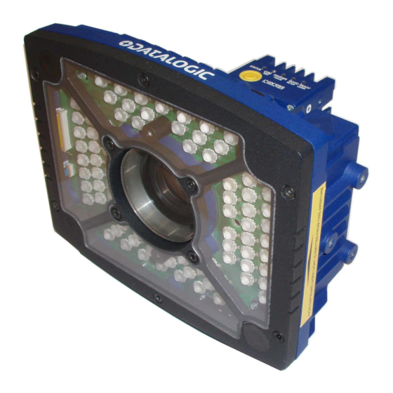
GENERAL VIEW Figure 1 - Matrix 450N + LT-03x 1. Device Class and Warning Labels 7. Power On LED 2. Bracket Mounting Holes (6) 8. Power - Serial - I/O Connector 3. Lens Cover 9. MAC Address Label 4. Lens (separate accessory) 10. -
Page 15: Rapid Configuration
RAPID CONFIGURATION STEP 1 - ASSEMBLE THE READER The first step to perform is to assemble the accessories that make up the Matrix 450N reader The lens and either an internal or an external illuminator must be used. This pro- cedure shows an LT-03x series lighting system. - Page 16 Figure 2 - Assembling Matrix 450N to LT-03x The bracket can be mounted in the reverse direction to create a compact version of the Matrix 450N + LT-03x assembly. The compact assembly however will reduce access to the lens for the focusing procedure.
-
Page 17: Required Accessories
Required Accessories The following table shows the correct lens/illuminator combinations to be used for Matrix 450N imager assembly. LENSES ILLUMINATORS Part Number Name C-Mount Lens Type Part Number Name Type 6 mm C-Mount Lens 93ACC0041 LNS-1216 5MP with anti-vibration 93A400034 LT-0032 Ultra Power LT Narrow Blue 40°... -
Page 18: Step 2 - Connect The System
When One Shot or Phase Mode Operating mode is used, the reader is activated by an External Trigger (photoelectric sensor) when the object enters its reading zone. Figure 3 - Matrix 450N in Stand Alone Layout with CBX to Ethernet Host Power Supply Connection: Use the PG-120 power Kit (3 versions for European, UK or US plug) and CAB-PG-0002 + BA400 connector to connect the PG-120 to the CBX. - Page 19 LT-03x is powered directly from the PG-120 through the CAB-PG-0105 cable. The CAB-LD-002 (with power) cable (provided with the LT-03x), is used to supply power to the Matrix 450N from the LT-03x. Matrix 450N connects directly to the Ether- net host through the Gigabit Ethernet connection (CAB-GE0x).
-
Page 20: Cbx100/Cbx500 Pinout For Matrix 450N
CBX100/CBX500 Pinout for Matrix 450N The table below gives the pinout of the CBX100/CBX500 terminal block connectors. Use this pinout when the Matrix 450N reader is connected by means of the CBX100/ CBX500: GROUP LABEL DESCRIPTION Power Supply Input Voltage +... -
Page 21: Step 3 - Mount And Position The Reader
STEP 3 - MOUNT AND POSITION THE READER 1. To mount the Matrix 450N + LT-03x assembly, use the L-shaped mounting bracket to obtain the most suitable position for the reader. The most common mounting configurations are shown in the figure below. Other mounting solutions are pro- vided in "... - Page 22 Chapter 6, Reading Features rect reading distance according to your application requirements. Rapid Configuration of the Matrix 450N reader can be made either through the X-PRESS interface (steps 4-6) which requires no PC con- nection, or by using the DL.CODE Configuration Program (steps 7-8).
-
Page 23: Step 4 - Focus The Reader
STEP 4 - FOCUS THE READER Matrix 450N provides a built-in tool called Blue Diamonds™ to aid focusing the reader. The Blue Diamonds are accessed through the X-PRESS Interface. 1. Remove the lens cover in order to focus the reader. -
Page 24: Step 5 - Calibrate Image Density
7. Replace the lens cover, screwing it tightly to the base. STEP 5 - CALIBRATE IMAGE DENSITY In order to function correctly to the fullest extent of its capabilities, Matrix 450N must acquire information regarding image density or PPI (pixels per inch). This calibration takes place through the X-PRESS Interface and the Grade A Barcode Test Chart included in the package. -
Page 25: Setup
If the calibration cannot be reached after a timeout of about 5 (five) seconds Matrix 450N will exit without saving the parameters to memory, the Setup LED will stop blinking and in this case Matrix 450N emits a long low pitched beep. PRODUCT REFERENCE GUIDE 11... -
Page 26: Learn
The Learn procedure ends when the Image Density value is successfully saved in the reader memory, the Learn LED will stop blinking and Matrix 450N emits 3 high pitched beeps. If the calibration cannot be reached after a timeout of about 3 (three) minutes Matrix 450N will exit without saving the parameters to memory, the Learn LED will stop blinking and in this case Matrix 450N emits a long low pitched beep. -
Page 27: Step 6 - X-Press Configuration
If the calibration cannot be reached after a timeout of about 5 (five) seconds Matrix 450N will exit without saving the parameters to memory, the Setup LED will stop blinking and in this case Matrix 450N emits a long low pitched beep. PRODUCT REFERENCE GUIDE 13... -
Page 28: Learn
The Learn procedure ends when the Image Processing and Decoding parameters for a single code are successfully saved in the reader memory, the Green Spot is acti- vated, the Learn LED will stop blinking and Matrix 450N emits 3 high pitched beeps... -
Page 29: Reset Reader To Factory Default Environment (Optional)
All the device’s Environment parameters are reset including the default IP Address. The Matrix 450N emits 3 high pitched beeps and after a few seconds enters run mode. Any previously saved configurations on the device will remain in memory, but the Default configuration is set as the startup configuration. -
Page 30: Step 7 - Installing Dl.code Configuration Program
NOTE 2. When the installation is complete the DL.CODE entry is created in the Start>Pro- grams bar under “Datalogic” as well as a desktop icon. Double-click the desktop icon to run it. This configuration procedure assumes a laptop computer, running DL.CODE, is con- nected to a factory default reader through the Ethernet port. -
Page 31: Device Discovery
Device Discovery The User Interface opens and displays a list of all the devices belonging to the Local Area Network. DL.CODE has a discovery feature to accomplish this task. Figure 15 - Device Discovery The discovery feature will also show devices not belonging to the LAN and display them in gray (see Figure 15). - Page 32 Figure 16 - Device Environment Configuration Window 6. Click OK; the device will reappear in the list of Online Devices (in color) meaning it is now part of the LAN and can be configured. The new IP address will also be dis- played. 18 MATRIX 450N...
- Page 33 7. Double-click on or drag the device icon into the Selected Device Information Area. Details about the device will be displayed in this area. Figure 17 - DL.CODE Opening Window PRODUCT REFERENCE GUIDE 19...
-
Page 34: Step 8 - Device Configuration
If your application requires multiple code symbologies, multiple image settings, Code Grading or other parameter settings for decoding, then use the Advanced Setup, see page 23. NOTE 20 MATRIX 450N... -
Page 35: Automatic Setup
Automatic Setup To begin configuration, the reader must be correctly mounted so that its Field of View covers the application reading area. 1. From the Task Area select Open Device Configuration. 2. The Open Device Configuration window opens showing the list of currently saved configurations (jobs) saved on the device. - Page 36 7. Click Start to begin the procedure. The reader begins acquiring images. At the end of the procedure the Status: Completed message appears. You can Close the Automatic Setup window. Your reader is now optimized for decoding. Continue with the Reading Phase configura- tion described on page 30. 22 MATRIX 450N...
-
Page 37: Advanced Setup
Advanced Setup To begin configuration, the reader must be correctly mounted at the correct reading dis- tance for your application so that its Field of View covers the application reading area. 1. From the Task Area select Open Device Configuration. 2. - Page 38 5. Click the Image Settings branch and then click the Image Auto-Setup button to automatically acquire the best exposure time and gain values. 24 MATRIX 450N...
- Page 39 6. Select the Static or Dynamic Self-Tuning option; Start the Image Auto Setup and Apply to the Image Settings. For applications having multiple lighting or code reading conditions, up to 10 different Image Settings can be configured by adding them with the NOTE icon.
- Page 40 To enlarge the visual image of the code and the oscilloscope views, you can drag the Focus Calibration window up and click on the zoom image icon repositioning it on the code. NOTE 26 MATRIX 450N...
- Page 41 While in run mode, manually adjust the focus until the bars relative to the code in the oscillo- scope demonstrate their maximum length (focus). You can also see the visual focus on the code view. When focused, click Pause to stop image acqui- sition.
- Page 42 NOTE 9. Now place an application specific code in front of the reader and repeat only the Image Auto-Setup to register any changes in lighting or code surface contrast. Do not repeat Focus Calibration or PPI. 28 MATRIX 450N...
- Page 43 10. Click on the Data Matrix ECC 200 symbology under the Image Settings branch (enabled by default). If this symbology is among those in your application it will be shown in the image display with its code symbology name and a small green box around it indicating it is decoded.
-
Page 44: Reading Phase
Parameters tree area: Continuous, One Shot, Phase Mode or PackTrack. 2. Configure the relative Operating Mode parameters from the Reading Phase parameters panel. Different groups will appear in the panel depending on the selected icons over the Configuration Parameters tree area. 30 MATRIX 450N... -
Page 45: Good Read Setup
Good Read Setup 1. Select your specific data collection type from the icons over the Configuration Parameters tree area: Code Collection, Code Combination, Presentation or Match Code. Not all data collection types are available for all Operating Modes; for exam- ple PackTrack Operating Mode only supports Code Combination. -
Page 46: Data Formatting
Field area. They will be appended to the message. You can drag them to position them between other fields in the message so that the output message is ordered according to your application requirements. Each field has its own relative configuration parameters in the parameters panel. 32 MATRIX 450N... -
Page 47: Output Setup
Output Setup 1. Configure your application specific Digital Output(s) and Green/Red Spots (if used) from the Configuration Parameters tree area: Output 1, Output 2, etc. Save the configuration from temporary memory to permanent memory, overwriting the previously saved configuration. NOTE PRODUCT REFERENCE GUIDE 33... -
Page 48: Step 9 - Test Mode
Bar-Graph shows the Good Read Rate. Figure 18 - X-PRESS Interface: Test Function 3. To exit the Test, press the X-PRESS push button once. By default, the Test exits automatically after three minutes. NOTE The Bar Graph has the following meaning: 34 MATRIX 450N... -
Page 49: Advanced Reader Configuration
ADVANCED READER CONFIGURATION For further details on advanced product configuration, refer to the DL.CODE User’s Guide available in the DL.CODE Help menu. Host Mode Programming The reader can also be partially configured from a host computer using the Host Mode programming procedure. -
Page 50: Introduction
INTRODUCTION PRODUCT DESCRIPTION Matrix 450N is a Datalogic industrial compact 2D imager dedicated to middle range applications in the Transportation and Logistic industry. Matrix 450N is an extremely powerful reader, capable to address ID applications never covered by a 2D Imager. -
Page 51: Standard Application Program
Manual Presentation Scanning Standard Application Program A Standard Application Program is factory-loaded onto Matrix 450N. This program con- trols code reading, data formatting, serial port and Ethernet interfacing, and many other operating and control parameters. It is completely user configurable from a Lap- top or PC using the dedicated configuration software program DL.CODE, provided on... -
Page 52: Ease Of Use
Industrial compact 2D reader • Rugged metal construction • Sealed circular M12 connectors • IP65 protection class • 50 °C max operating temperature • Supply voltage ranges from 10 to 30 Vdc for Matrix 450N (LT-03x requires 24 Vdc) 38 MATRIX 450N... -
Page 53: Indicator And Keypad Button
INDICATOR AND KEYPAD BUTTON 5 4 3 Figure 19 - Indicators The following LED indicators are located on the reader: blue LED indicates that the reader is connected to the power supply (Figure 19, 1) blue LED indicates connection to the on-board Ethernet network (Figure 19, In normal operating mode the colors and meaning of the five LEDs are illustrated in the following table: READY... -
Page 54: Id-Net
Thanks to ID-NET, data communication among readers is highly efficient so that an immediate result will be available. See " for connection details and " ID-NET Interface" on page 70 Internal Network Configura- for configuration details. tions" on page 129 40 MATRIX 450N... - Page 55 • ID-NET Multidata: Multiple stations – single reader ID-NET interface allows connection of readers reading objects placed on independent conveyors. All readers are typically located far away from each other and they can have different operating modes from each other. At the end of each reading phase, each reader transmits its own data message to the host.
-
Page 56: X-Press Human Machine Interface
Test with bar graph visualization to check static reading performance • Focus/Locate to turn on the Blue Diamonds to aid focusing and positioning • Setup to perform Exposure Time and Gain calibration • Learn to self-detect and auto-configure for reading unknown codes 42 MATRIX 450N... -
Page 57: X-Press Functions
X-PRESS Functions Quick access to the following functions is provided by an easy procedure using the push button: 1. Press the button (the Status LED will give a visual feedback). 2. Hold the button until the specific function LED is on (Test, Focus, Setup or Learn). 3. -
Page 58: Focus/Locate
The Setup LED will blink until the procedure is completed. The Setup procedure ends when the Image Acquisition parameters are successfully saved in the reader memory, the Setup LED will stop blinking and Matrix 450N emits 3 high pitched beeps. -
Page 59: Diagnostic Indication
Ready Blink Good Trigger Status Blink MODEL DESCRIPTION The Matrix 450N reader is described by the following characteristics. Lens/Illuminator Selection The following table shows the correct lens/illuminator combinations to be used for Matrix 450N imager assembly. LENSES ILLUMINATORS Part Number... -
Page 60: Accessories
ACCESSORIES The following accessories can be used with the Matrix 450N reader. Accessory Description Order No. Lenses LNS-1216 16 mm C-Mount Lens 5MP with anti-vibration components 93ACC0041 LNS-1225 25 mm C-Mount Lens 5MP with anti-vibration components 93ACC0034 LNS-1235 35 mm C-Mount Lens 5MP with anti-vibration components... - Page 61 Photocell Kit PNP (PH-1) 93ACC1791 MEP-543 Photocell Kit-NPN 93ACC1728 Brackets BK-45-000 LT-03x L-shaped Mounting Bracket 93ACC0049 BK-45-010 Matrix 450N Body Mounting Bracket 93ACC0050 BK-45-040 Alternative Fixing Brackets for External Mirror (2 pcs) 93A201208 External Mirrors EMK-MTX-380 External Mirror - 380 mm 93ACC0086 EMK-TMX-600...
- Page 62 Software Management WebSentinel PLUS license images 5 arrays 93A101027 WebSentinel PLUS license images 10 arrays 93A101028 WebSentinel PLUS license images 20 arrays 93A101029 WebSentinel PLUS license images 32 arrays 93A101030 WebSentinel PLUS license images 64 arrays 93A101031 48 MATRIX 450N...
-
Page 63: Application Examples
Flyers, small parcels and letter packs are manually moved across the Matrix 450N scan- ning zone, where two laser pointers mark the center. The Sort-to-Light mode is one of... -
Page 64: Automated Postal Sorting
Matrix 450N can also be applied in scanning applications of large conveyors or multi- sided reading. Through the ID-NET clustering, multiple readers can be effectively com- bined to extend the scanning area. -
Page 65: Multimedia And Flats
Because of the outstanding intrinsic DOF with fixed focus, it does not need any height measurement, therefore definitely simplifying the integration and eliminating any extra hardware. Low aspect ratio codes have no impact on the simplicity of the Matrix 450N reading solution, since regular image capture contains any scanning pattern inside the reading area, and therefore always the maximum level of data integrity. -
Page 66: Static Scan
Matrix 450N is a valid solution for scanning large stationary objects, from pallets to stacked trays. There are multiple advantages in using Matrix 450N. First of all, no parts in movement – no scan rotor and no oscillating mirror – delivers crucial advantages in terms of maxi- mum tolerance to vibration and shock, as for example a forklift may generate. -
Page 67: Installation
CHAPTER 3 INSTALLATION PACKAGE CONTENTS Verify that the Matrix 450N reader and all the parts supplied with the equipment are present and intact when opening the packaging; the list of parts includes: • Matrix 450N reader • Quick Reference Guide •... -
Page 68: Mechanical Dimensions
MECHANICAL DIMENSIONS Matrix 450N is designed to be used with one of the LT-03x Series Lighting Systems. In this configuration the L-shaped LT-03x mounting bracket must be used to support the whole assembly (refer to Figure 22). In alternative applications Matrix 450N can be installed with an External Illuminator or custom lighting system (LT-03x is not mounted). - Page 69 Figure 22 - Matrix 450N + LT-03x + L-Bracket Overall Dimensions PRODUCT REFERENCE GUIDE 55...
-
Page 70: Mounting And Positioning Matrix 450N
Using the LT-03x L-shaped mounting bracket you can obtain rotation on the various axes of the reader as shown in the diagrams below: Figure 23 - Mounting LT-03x Bracket Figure 24 - Matrix 450N Positioning with LT-03x Bracket 56 MATRIX 450N... - Page 71 Figure 26 - Positioning with Matrix 450N Body Mounting Bracket (Back) Matrix 450N is able to decode code labels at a variety of angles; however significant angular distortion may degrade reading performance.
- Page 72 The Pitch, Skew and Tilt angles are represented in Figure 27. Follow the suggestions below for the best orientation. Position the reader in order to avoid the direct reflection of the light emitted by the Matrix 450N reader; it is advised to assure at least 10° for the Skew angle. Skew Tilt assure at least 10°...
-
Page 73: Mounting With Emk Mirrors
MOUNTING WITH EMK MIRRORS Accessory EMK series External Deflection Mirrors can be mounted in all applications where it is not practical to use the full DOF of the reader. In these cases a more compact reading station can be constructed. This is particularly useful in side reading applica- tions. -
Page 74: Emk-380 Side Mount - Standard
EMK-380 Side Mount - Standard Matrix 450N and EMK-380 Mirror alignment is maintained when the EMK is mounted directly to the frame profiles. The skew angle is made at the mirror instead of at the reader. 1. Mount the mirror brackets to the... -
Page 75: Emk-380 Side Mount - Alternative
An alternative mounting solution is to use the BK-90-040 brackets included in the pack- age. Matrix 450N and EMK-380 Mirror alignment is obtained when the EMK is centered to the frame profiles as shown in the figures below. These brackets also provide the freedom of applying offsets to the mirror where necessary. -
Page 76: Emk-600 Side Mount - Standard
The EMK-600 mirror can be used together with two Matrix 450N readers in applications where a larger Field of View (FoV) is required. Matrix 450N and EMK-600 Mirror align- ment is maintained when the EMK is mounted directly to the frame profiles. The skew angle is made at the mirror instead of at the reader. -
Page 77: Emk-600 Side Mount - Alternative
5. Move the mirror assembly to the correct distance from the readers according to your application. 6. Position the Matrix 450N readers vertically to center them according to your appli- cation drawings. 7. Tighten the bolts. -
Page 78: Cbx Electrical Connections
CHAPTER 4 CBX ELECTRICAL CONNECTIONS All Matrix 450N models can be connected to a CBX connection box through one of the available CAB-DSxx-S accessory cables. These accessory cables terminate in a 19-pin connector on the Matrix 450N side and in a 25-pin male D-sub connector on the CBX side. -
Page 79: Cbx Connection Box Pinout
CBX CONNECTION BOX PINOUT The table below gives the pinout of the CBX100/500 terminal block connectors. Use this pinout when the Matrix 450N reader is connected by means of the CBX100/500: Group Label Description Input Power Supply Input Voltage +... -
Page 80: Power Supply
POWER SUPPLY Matrix 450N does not support sourcing power towards the CBX through the CBX "power from device" source jumper setting. Power must be sup- plied to the CBX as shown below. NOTE Power can be supplied to the reader through the CBX100/500 spring clamp terminal... -
Page 81: Recommended Power Supplies
PWR-120 PWR-480B If using separate power sources for LT-03x and Matrix 450N, make sure that LT-03x is powered up before Matrix 450N in order to be correctly recognized. NOTE If using customer supplied power, keep in mind the following worst case peak current consumption diagram. -
Page 82: Main Serial Interface
CBX100/500 Description Transmit Data Receive Data SGND Signal Ground It is always advisable to use shielded cables. The overall maximum cable length must be less than 15 m (49.2 ft). Figure 31 - RS232 Main Interface Connections 68 MATRIX 450N... -
Page 83: Rs422 Full Duplex Interface
RS422 Full Duplex Interface The RS422 full-duplex (5 wires + shield) interface is used for non-polled communication protocols in point-to-point connections over longer distances (max 1200 m / 3940 ft) than those acceptable for RS232 communications or in electrically noisy environments. The CBX pinout follows: CBX100/500 Description... -
Page 84: Id-Net Interface
250 kbps 500 kbps 1 Mbps Cable Length 1200 m 900 m 700 m * Application dependent, contact your Datalogic representative for details. The default ID-NET baudrate is 500 kbps. Lower ID-NET baudrates allow longer cable lengths. NOTE 70 MATRIX 450N... -
Page 85: Id-Net Response Time
ID-NET Response Time The following figure shows the response time of the ID-NET network. This time is defined as the period between the Trigger activation and the beginning of data trans- mission to the Host. Figure 34 - ID-NET Response Time Conditions •... -
Page 86: Id-Net Network Termination
The network must be properly terminated in the first and last reader of the network. This is done by setting the ID-NET Termination Resistance Switch in the CBX100/500 to ID-NET Connection Diagrams Figure 35 - ID-NET Network Connections with isolated power blocks 72 MATRIX 450N... - Page 87 Figure 36 - ID-NET Network Connections with Common Power Branch Network PRODUCT REFERENCE GUIDE 73...
- Page 88 Figure 37 - ID-NET Network Connections with Common Power Star Network 74 MATRIX 450N...
-
Page 89: Auxiliary Rs232 Interface
AUXILIARY RS232 INTERFACE The RS232 auxiliary interface is available for Point-to-Point connections. When it is con- nected to the host computer it allows transmission of code data. The parameters relative to the aux interface (baud rate, data bits, etc.) can be defined through the Reading Phase step (Channels) in DL.CODE. -
Page 90: Inputs
Power Source - External Trigger External Trigger A (polarity insensitive) External Trigger B (polarity insensitive) Power Reference - External Trigger The yellow Trigger LED (Figure 19, 5) is on when the active state of the External Trigger corresponds to ON. 76 MATRIX 450N... -
Page 91: External Trigger Input Connections Using Matrix 450N Power
Device on the +V/-V spring clamps, and does not pass through the Power Switch (ON/OFF) inside the CBX. Disconnect the power supply when CAUTION working inside the CBX. Figure 40 - PNP External Trigger Using Matrix 450N Power PRODUCT REFERENCE GUIDE 77... - Page 92 Figure 41 - NPN External Trigger Using Matrix 450N Power 78 MATRIX 450N...
-
Page 93: External Trigger Input Connections Using External Power
External Trigger Input Connections Using External Power Figure 42 - PNP External Trigger Using External Power Figure 43 - NPN External Trigger Using External Power CBX100/500 Description Power Source - External Trigger Input 2 A (polarity insensitive) Input 2 B (polarity insensitive) Power Reference - External Trigger PRODUCT REFERENCE GUIDE 79... -
Page 94: Input 2 Connections Using Cbx Power
Device on the +V/-V spring clamps, and does not pass through the Power Switch (ON/OFF) inside the CBX. Disconnect the power supply when CAUTION working inside the CBX. Figure 44 - PNP Input 2 Using CBX Power Figure 45 - NPN Input 2 Using CBX Power 80 MATRIX 450N... -
Page 95: Input 2 Connections Using External Power
Input 2 Connections Using External Power Figure 46 - PNP Input 2 Using External Power Figure 47 - NPN Input 2 Using External Power PRODUCT REFERENCE GUIDE 81... -
Page 96: Outputs
Good Read event, which activates when all the selected codes are correctly decoded. The output signals are fully programmable being determined by the configured Activa- tion/Deactivation events, Deactivation Timeout or a combination of the two. Refer to the DL.CODE parameters Help On Line for further details. 82 MATRIX 450N... -
Page 97: Output 1 And 2 Connections Using Cbx Power
Output 1 and 2 Connections Using CBX Power Power from the Vdc/GND spring clamps is available directly to the Out- put Device on the +V/-V spring clamps, and does not pass through the Power Switch (ON/OFF) inside the CBX. Disconnect the power supply CAUTION when working inside the CBX. -
Page 98: Output 1 And 2 Connections Using External Power
Output 1 and 2 Connections Using External Power Figure 50 - PNP/Open Emitter Output Using External Power Figure 51 - NPN/Open Collector Output Using External Power 84 MATRIX 450N... -
Page 99: On-Board Gigabit Ethernet Interface
The on-board Gigabit Ethernet Interface can be used for TCP/IP communication with a remote or local host computer by connecting the reader to either a LAN or directly to a host PC. There is no need to use a crossover adapter since Matrix 450N incorporates an auto-cross function. -
Page 100: Typical Layouts
SYNCHRONIZED ID-NET network configurations are also configurable as before. The Master/Slave Role is only significant for the Internal ID-NET Net- work. If your layout doesn’t use the ID-NET network then the device’s Role is not significant and can be ignored. NOTE 86 MATRIX 450N... -
Page 101: Ethernet Connection
The Ethernet connection is possible in two different layouts. In a Point-to-Point layout the reader is connected to a local host by using a CAB-GE0x Gigabit Ethernet cable. There is no need to use a crossover adapter since Matrix 450N incorporates an autocross function. - Page 102 When using a Local Area Network (LAN), one or more Matrix 450N readers can be con- nected to the same network by using CAB-GE0x Gigabit Ethernet cables. Figure 54 - Ethernet Network Layout All devices always support multiple output channels (i.e. for data monitoring).
-
Page 103: Serial Connection
SERIAL CONNECTION In this layout the data is transmitted to the Host on the main serial interface. The Ether- net interface can be used for reader configuration by connecting a laptop computer run- ning DL.CODE. Data can be transmitted on the RS232 auxiliary interface independently from the main interface selection to monitor data. -
Page 104: Fieldbus Connection
When One Shot or Phase Mode operating mode is used, the reader can be activated by an External Trigger (photoelectric sensor) when the object enters its reading zone. Figure 56 - Fieldbus Interface Point-to-Point Layout All devices always support multiple output channels (i.e. for data monitoring). 90 MATRIX 450N... -
Page 105: Pass-Through
PASS-THROUGH The pass-through layout allows each device working Alone, to collect data from one or more pass-through input channels and send this data plus its own on one or more dif- ferent output channels. In this way independent devices can be connected together in combinations to create multi device networks. -
Page 106: Id-Net Multidata Network (Pass-Through)
Master devices cannot send data on an ID-NET output chan- nel. NOTE All devices always support multiple output channels (i.e. for data monitoring). In a Pass-through layout each device can have a different operating mode: Continuous, One Shot, Phase Mode, etc. 92 MATRIX 450N... -
Page 107: Id-Net Synchronized Network
ID-NET SYNCHRONIZED NETWORK When the device is working Synchronized, the ID-NET connection is used to collect data from several readers to build a multi-point or a multi-sided reading system; there can be one Master and up to 31 Slaves connected together. The Slave readers are connected together using the ID-NET interface. - Page 108 If the Backup and Restore function is not required, then a QL300 can be used to connect the master reader. Figure 61 - ID-NET Synchronized Layout with Master Main Serial Interface to Serial host Matrix 450N Master with QL300 + Matrix 450N Slaves with QL100 94 MATRIX 450N...
- Page 109 Alternatively, the Master reader can communicate to the Host as a Slave node on a non TCP/IP compatible Fieldbus network (DeviceNet, Profibus, etc.). This requires using an accessory HMS Fieldbus interface board installed inside the CBX500 connection box. System configuration can be accomplished through the Ethernet interface of each indi- vidual reader using the DL.CODE configuration program.
-
Page 110: Reading Features
= 2 [ (d + 44) * tan (α /2) ] where: = horizontal, vertical or diagonal FOV = horizontal, vertical or diagonal viewing angles. d = reading distance (in mm) from window surface to code surface 96 MATRIX 450N... - Page 111 Figure 63 - Reading Distance References Example The FOV for a Matrix 450N 800-030base using the 16 mm lens at a reading distance of 1000 mm is: = 2 [(1000 mm + 44 mm) * tan (28.8°/2)] 536 mm = 2 [(1000 mm + 44 mm) * tan (24.5°/2)] ...
-
Page 112: Reading Diagrams
Data Matrix ECC 200 (2D code) from the Test Charts provided with the reader. • Testing should be performed with the actual Matrix 450N + LT-03x assembly using application codes in order to evaluate whether maximizing application perfor- mance requires adjustments to the HW/SW configuration with respect to the Ref- erence Conditions given under each diagram. -
Page 113: Matrix 450N + Lns-1216
Matrix 450N + LNS-1216 Hardware Settings Code Symbology Code 128 Code Resolution 0.38 mm (15 mils) 0.50 mm (20 mils) Focal Length 16 mm Aperture Stop Focus Distance 1200 mm (47.2 in) 1400 mm (55.1 in) Tilt Angle 45° Skew Angle 15°... -
Page 114: Matrix 450N + Lns-1225
Matrix 450N + LNS-1225 Hardware Settings Code Symbology Code 128 Code Resolution 0.20 mm (8 mils) Focal Length 25 mm Aperture Stop F/5.6 Focus Distance 1000 mm (39.4 in) Tilt Angle 45° Skew Angle 15° Lighting System LT-030 LT-031 LT-032 Software Parameters Exposure Time (μs) - Page 115 Hardware Settings Code Symbology Code 128 Code Resolution 0.20 mm (8 mils) 0.38 (15 mils) Focal Length 25 mm Aperture Stop F/5.6 Focus Distance 1700 mm (66.9 in) 1900 mm (74.8 in) Tilt Angle 45° Skew Angle 15° Lighting System LT-030 LT-031 LT-032...
- Page 116 3.2 m/s 3.2 m/s 2.5 m/s Gain Internal Lighting Very High Power Strobed or Continuous High Power Processing Mode Advanced Standard Minimum Code Height (mm) Narrow Quiet Zone Enabled Code Contrast / Decoding Low / Medium Complexity 102 MATRIX 450N...
- Page 117 Hardware Settings Code Symbology Code 128 Code Resolution 0.51 mm (20 mils) Focal Length 25 mm Aperture Stop F/5.6 Focus Distance 2500 mm (98.4 in) Tilt Angle 45° Skew Angle 15° Lighting System LT-030 LT-031 LT-032 Software Parameters Exposure Time (μs) Max code moving speed 1.8 m/s 1.8 m/s...
- Page 118 Matrix 450N + LNS-1235 Hardware Settings Code Symbology Code 128 Code Resolution 0.20 mm (8 mils) Focal Length 35 mm Aperture Stop F/11 Focus Distance 1450 mm (57.1 in) Tilt Angle 45° Skew Angle 15° Lighting System LT-030 LT-031 Software Parameters Exposure Time (μs)
- Page 119 Hardware Settings Code Symbology Code 128 Code Resolution 0.25 mm (10 mils) 0.30 mm (12 mils) Focal Length 35 mm Aperture Stop F/11 Focus Distance 1800 mm (70.9 in) 2300 mm (90.5 in) Tilt Angle 45° Skew Angle 15° Lighting System LT-030 LT-031 LT-030...
- Page 120 LT-031 Software Parameters Exposure Time (μs) Max code moving speed 2.0 m/s 1.0 m/s 3.0 m/s 1.7 m/s Gain Internal Lighting Very High Power Strobed or Continuous High Power Processing Mode Standard Code Contrast Decoding Complexity Medium 106 MATRIX 450N...
- Page 121 Matrix 450N + LNS-1250 Hardware Settings Code Symbology Code 128 Code Resolution 0.15 mm (6 mils) Focal Length 50 mm Aperture Stop Focus Distance 1600 mm (62.9 in) Tilt Angle 45° Skew Angle 15° Lighting System LT-030 LT-031 Software Parameters Exposure Time (μs)
-
Page 122: Maximum Line Speed And Exposure Time Calculations
0.254 (mm) / 0.0001 (s) = 2540 mm/s Likewise, T is the maximum Exposure Time value that can be used without blur- exp (max) ring for the given application line speed and code resolution. Therefore: X / LS = T exp (max) 108 MATRIX 450N... - Page 123 and LS are represented in the graph below as the curved line for X (code exp (max) (max) resolution). Values above the curve result in blurring. In practice, the application values are somewhere below the theoretical line, (in the green area), due to environmental and other conditions.
-
Page 124: Software Configuration
CHAPTER 7 SOFTWARE CONFIGURATION Software configuration of your Matrix 450N for static reading or simple code reading applications can be accomplished by the Rapid Configuration procedure using the X-PRESS HMI (which requires no external configuration program). This procedure is described in Steps 4-6. -
Page 125: Auto-Calibration
When all the configuration parameters are set correctly and saved to the device, you can perform a Backup to File and/or to an External storage device (BM100, etc.). See " Backup and Restore Through DL.CODE" on page 144 An improvement in the Matrix N Family readers allows them to contain several configurations or jobs in permanent memory. -
Page 126: Manual Calibration
Internal Lighting mode parameter. Longer exposure times NOTE can be set if the power strobe level is lowered. High gain settings may produce a grainy image that may affect the decoding process. Figure 65 - Example Under Exposure: Too Dark 112 MATRIX 450N... -
Page 127: Over-Exposure
Over-exposure To correct this result it is recommended to change the following parameters in their order of appearance: 1. decrease the Gain 2. decrease the Exposure Time Figure 66 - Example Over Exposure: Too Light PRODUCT REFERENCE GUIDE 113... -
Page 128: Moving Code Out Of The Field Of View
• reposition the reader • use the Delay on Trigger and set the Time or Space values. Figure 67 - Example Out of FOV Figure 68 - Add Delay on Trigger to Correct Out of FOV 114 MATRIX 450N... -
Page 129: Multi Image Acquisition Settings
MULTI IMAGE ACQUISITION SETTINGS When controlled variable conditions occur in the application, Multiple Image Acquisi- tion Settings can be defined to create a database of parameter groups that handle each specific application condition. This database of pre-defined settings improves system flexibility and readiness by being applied either automatically or selectively by an activa- tion event. -
Page 130: Automatic Image Settings Selection
Last Successful value, we will start with the Image Setting that last produced a Good Read. For this group of items the last Image Setting used will be correct for the next item and so we start each cycle with the acquisition that will potentially produce a Good Read. 116 MATRIX 450N... -
Page 131: External Image Settings Selection
External Image Settings Selection There are some applications where the lighting conditions are known before each item is read and therefore we can pre-select the correct Image Setting from an external source. When the Image Settings Selection is External, Acquisition Sequences are created and by default each Image Setting has its own Acquisition Sequence. - Page 132 In this case the Start Acquisition From parameter can improve the read rate for that Sequence. It has no meaning for a Sequence containing only one Image Setting. 118 MATRIX 450N...
-
Page 133: Image Cropping
Setup tab by clicking on the Add Cropping Region icon as shown below. In Matrix 450N the frame rate is dependent on the number of rows and columns in the defined window. Image cropping allows reducing the Image processing area from the full FoV to a smaller area where codes are present. - Page 134 The numbers in the blue boxes refer to pixel refer- ences. x,y coordinates of upper left corner of Cropping Region number of pixels in vertical Cropping Region (Height) The cropped area can be moved by dragging the center. 120 MATRIX 450N...
- Page 135 You can also set the cropped image size and position through the Cropping Region Area group of parameters; size = Width and Height, position = Left, Top (x,y) coordinates. PRODUCT REFERENCE GUIDE 121...
-
Page 136: Direct Part Marking Applications
For QR code the Decoding Method parameter allows the Dot Peen Decoding algorithm to be selected which improves the decode rate for low quality Direct Part Mark codes and in general for Direct Part Mark codes with dot peening type module shapes. 122 MATRIX 450N... -
Page 137: Image Filter
Image Filter Sets the filter to be applied to the image before being processed. This parameter can be used to successfully decode particular ink-spread printed codes (e.g. direct part mark codes). Different filters can be applied to a single code or group of codes in one or more Image Settings. - Page 138 The Open filter eliminates white areas (defects) in the dark zones of the image. Before - No Read After - Readable The Contrast Stretching filter maximizes image contrast. Before - No Read After - Readable 124 MATRIX 450N...
- Page 139 The Histogram Equalization filter makes the gray level distribution uniform. Before - No Read After - Readable The Smoothing filter deletes small (insignificant) details in the center of the image. Before - No Read After - Readable The Sharpening filter improves out of focus images. Before - No Read After - Readable PRODUCT REFERENCE GUIDE 125...
- Page 140 The Deblurring filter improves blurred images. Before - No Read After - Readable The Black Enhancement filter produces a nonlinear increase in the black level for light images. Before - No Read After - Readable 126 MATRIX 450N...
-
Page 141: Pass-Through Configurations
The White Enhancement filter produces a nonlinear increase in the white level for dark images. Before - No Read After - Readable PASS-THROUGH CONFIGURATIONS Starting from software version 1.3.0, DL.CODE and Matrix N familiy readers support pass-through multi device configurations. The pass-through configuration allows individually working devices (Alone), to collect data from other devices (also working Alone), and pass this data to a third device through a different communication channel. - Page 142 Reader #2 Reader #3 128 MATRIX 450N...
-
Page 143: Internal Network Configurations
1. Mount all the readers mechanically (refer to " Mechanical Dimensions" on page 54 and " ) and electrically (refer to Mounting And Positioning Matrix 450N" on page 56 " ) with factory default settings (Layout Type = Alone, ID-NET Interface" on page 70 Internal Network Role = Slave). -
Page 144: Master Configuration
Slave). Click on Setup Internal Network Configuration from the Task area. You will be advised that the device role will be changed to Master. Click OK. The Net Autoset feature automatically starts to find Slave devices connected to the ID-NET network of the Master. 130 MATRIX 450N... - Page 145 When finished, all the Slaves should have been correctly recognized. If not, verify all device connections and power and then repeat the operation by clicking on the Start Net Autoset button. Repeat Depending on the application, select one of the Default Internal Network Configura- tions: Multidata, Synchronized Phase Mode or Synchronized PackTrack.
-
Page 146: Multidata Id-Net Network Configurations
DL.CODE. This is preferably done through each device’s Ethernet TCP/IP channel. If Slave devices are not NOTE connected to Ethernet you must temporarily (manually) connect them one by one to perform Image Settings. 132 MATRIX 450N... - Page 147 Open the Slave specific application job, (it will either have the new name saved from the Master or Temp depending on the Save on Slave Device selection). PRODUCT REFERENCE GUIDE 133...
- Page 148 When the configuration opens, pause run mode and set all the application specific con- figuration parameters (including Image Settings). Verify the focus and decoding with the capture image button. 134 MATRIX 450N...
- Page 149 3. Now save them to a new Slave specific application job Figure 71 - Saving Multidata Configuration to Slave 1 Repeat this procedure for each Slave device until the entire network is configured. The following screenshots show the pass-through configuration settings. 1.
- Page 150 136 MATRIX 450N...
-
Page 151: Synchronized Id-Net Network Configurations
Synchronized ID-NET Network Configurations The Synchronized ID-NET network communications between Master and Slave are inter- nally managed by the application software. A pre-configured job is loaded with the Syn- chronized Layout Type and the correct Operating Mode for both the Master and Slaves when either the Phase Mode or PackTrack Configuration is selected from the Internal Network Setting feature. - Page 152 Open the cloned application job. 138 MATRIX 450N...
- Page 153 When the job opens, pause run mode and configure the Slave specific parameters. These depend on the application and include the following: • photometric parameters (Image Auto-Setup feature in the Advanced Setup – Image Settings step) • Acquisition Trigger Delays necessary to avoid lighting interference between adja- cent or oppositely positioned readers (Reading Phase step) •...
- Page 154 Slave can have its own Image Settings parameters saved in its own copy of the application job. Common parameters managed by the Master such as Operating Mode cannot be modified in the Slave jobs and are shown in dark gray. 140 MATRIX 450N...
-
Page 155: Verify Master/Slave Synchronized Configuration
Verify Master/Slave Synchronized Configuration From the Master configuration, run the application and monitor the output data from the DL.CODE Console or a configured channel terminal. If necessary, as a troubleshooting tip, you can temporarily apply the Reading Mask field in place of each Code Content field to verify if all devices are reading. To do this: 1. - Page 156 4. If you haven’t made any other changes you can exit without saving. Otherwise, save the Master device configuration overwriting its previous one, making sure to save without Clone Master Configuration on Slaves, otherwise the Slave configu- rations will be overwritten. 142 MATRIX 450N...
- Page 157 To view the connected Slave configurations: 1. Click on the Internal Network View tab at the bottom of the screen. 2. Open the Master branch by clicking on the arrow to the left of the Master icon. 3. Select any slave. Wait for the configuration to load. 4.
-
Page 158: Backup And Restore Through Dl.code
DL.CODE for all reading devices when connected to: • CBX + BM100 • QLM-Series Gateways Before executing a Backup to a BM100 backup module make sure the Write Protection switch is set to Unlocked. NOTE 144 MATRIX 450N... -
Page 159: Backup
Backup To perform a Backup: 1. From the DL.CODE Device menu, select either Single Reader Backup (to file on PC); or Backup to external storage device. For ID-NET network Backup, select the Backup current Internal Network configurations selection. NOTE You will be reminded that configuration in temporary memory will not be saved so you should save the configuration to the reader before performing Backup. -
Page 160: Restore
3. Run the Restore procedure by selecting either Single Reader Restore (from file on PC) or Restore from external storage device item (see: Restore procedure). In case of Backup or Restore operation failures, error messages will be displayed in the Monitor Diagnostic page. NOTE 146 MATRIX 450N... -
Page 161: Restore Defaults
RESTORE DEFAULTS The device parameters are divided into two main classes, Configuration and Environ- ment which are affected differently by the Restore Defaults commands. • The Configuration parameters are the ones set in the various steps of the configu- ration process and are specific to each application. When multiple configurations (jobs) are saved on a single device, these parameters can be different from one configuration to the next. -
Page 162: Restore Default Environment
All Environment parameters will be restored to Factory default values and any existing configurations stored on the device will be erased. The device will be reset and there- fore start in run mode with the factory default configuration. 148 MATRIX 450N... -
Page 163: Diagnostic Alarms
DIAGNOSTIC ALARMS By using the DL.CODE Monitor functions from the File menu (or Monitor icon), you can get information about diagnostic alarms. Any alarms will show up as warning lights on the alarm panel. Figure 74 - Diagnostic Alarms PRODUCT REFERENCE GUIDE 149... -
Page 164: Statistics
Statistics on the reading performance can be viewed by enabling the Statistics panel from the DL.CODE Monitor item selected from the File menu (or Monitor icon). Figure 75 - Reading Statistics The enabled Statistical Counters can be selected from the Device>Settings>Configura- tion Settings menu. 150 MATRIX 450N... -
Page 165: Bm150 Display Module Configuration And Messages
BM150 DISPLAY MODULE CONFIGURATION AND MESSAGES The BM150 display module is an optional accessory for the CBX500 connection box. Although independent, it is an extension of the reader's HMI Interface, so through its keypad it provides execution of HMI features such as Test, Focus/Locate, Calibration and Code Setting. -
Page 166: Accessing The Hmi Interface Through Keypad And Display Menu
HMI function the display shows a result message and then automatically exits from the menu structure. To exit a menu manually, press and release the Enter key at the [Exit] item or press the Up and Down buttons simultaneously. 152 MATRIX 450N... - Page 167 To exit from a running HMI function, press the Up and Down buttons simultaneously. These functions will also exit upon their configured timeout. When the HMI Interface is entered from either the Local Device (reader) or Remote Device (BM150), the key(s) on the other device are disabled. NOTE When the reader is connected to DL.CODE, access to the BM150 HMI Interface is disabled.
-
Page 168: Display Messages
Test Mode Results A = reading percentage from 000 to 100%. Z = code content. Calibration (Setup) Results X = exposure value (in s). G = gain value Code Setting (Learn) Results X = recognized code symbology. 154 MATRIX 450N... - Page 169 Diagnostic Alarms Diagnostic error messages are sent to the BM150 display as numeric Alarm Codes (even if Failure Messages are selected for data transmission the numeric Alarm Code is sent to the display). X = numeric Alarm Code (see below for the list of Alarm Codes) R = Device Network Type –...
- Page 170 U = Diagnostic condition for Stand Alone or Master plus Slave readers 1 - 15: * = reader OK - = reader not detected at startup ? = reader detected at startup but not responding to diagnostic polling ! = reader diagnostic error 156 MATRIX 450N...
-
Page 171: Bm150 Backup And Restore Procedure
BM150 Backup and Restore Procedure The Backup and Restore functions are valid for any application layout type (point-to- point, network, etc.) using CBX500 connection boxes through the BM100 Backup mod- ule (required accessory for BM150 installation). The Backup and Restore functions are managed through the BM150 display and keypad and therefore are disabled at the BM100 Backup/Restore button. -
Page 172: Maintenance
General View" on page xiv Dust, dirt, etc. on the lens cover may alter the reading performance. Repeat the operation frequently in particularly dirty environments. Use soft material and alcohol to clean the lens cover and avoid any abrasive substances. 158 MATRIX 450N... -
Page 173: Troubleshooting
• If you’re unable to fix the problem and you’re going to contact your local Datalogic office or Datalogic Partner or ARC, we suggest providing (if possible): Application Program version, Parameter Configuration file, Serial Number and Order Number of your reader. - Page 174 Data Formatting parameters on the Data Format- no result is transmit- ting step. ted by the reader at the end of the reading phase collection. Image not clear: verify the Focus procedure Image focused but verify the Calibrate Image Density procedure. not decoded: 160 MATRIX 450N...
- Page 175 The reader Order Number can be obtained by comparing the reader Order Num- Device Model (in DL.CODE Device Menu > Settings > Settings > ber? About Device) with the product models page on the Datalogic website. PRODUCT REFERENCE GUIDE 161...
-
Page 176: Technical Features
TECHNICAL FEATURES ELECTRICAL FEATURES Standard Models Power Supply Voltage 24 Vdc ± 20% 2.5 A Matrix 450N; 2 A LT-03x) Consumption (max.) Recommended Power Supplies" on page 67 see " Communication Interfaces Main: RS232, RS422 Full-duplex 2400 to 115200 bit/s... - Page 177 H x W x L Matrix 450N 123 x 64 x 143 mm (4.8 x 2.5 x 5.6 in) Matrix 450N + LT-03x 202 x 213 x 179 mm (8.0 x 8.4 x 7.1 in) Weight 3000 g (6.6 lbs)
- Page 178 Code 128, Code 39, Interleaved 2 of 5, Codabar, Code 93, ISO/IEC 15416 EAN-8-13, UPC-A/E USER INTERFACE Power, Ready, Good; Trigger; Com, Status, (Ethernet Network); LED Indicators (Green Spot); (Red Spot); Laser Pointers Keypad Button Configurable via DL.CODE 164 MATRIX 450N...
-
Page 179: Alternative Connections
The Matrix 450N reader is equipped with an M16 19-pin male connector (Binder, 423 Series) for connection to the power supply, serial interfaces, and input/output signals. The details of the connector pins are indicated in the following table. Matrix 450N can- not source power through this connector. - Page 180 In order to meet EMC requirements: • connect the reader chassis to the plant earth ground by means of a flat copper braid shorter than 100 mm; • connect your cable shield to the locking ring nut of the connector. 166 MATRIX 450N...
-
Page 181: Matrix 450N Lighting System Control Connector
MATRIX 450N LIGHTING SYSTEM CONTROL CONNECTOR Matrix 450N controls the LT-03x series lighting system from this connector through soft- ware. Matrix 450N can also receive power from this input, normally from the LT-03x lighting system through the CAB-LD-002 cable. Matrix 450N cannot source power through this connector. -
Page 182: 03X Input Power Connector (On Lt-03X)
Figure 3 - M12 4-pin male LT-03x Input Power Connector ON-BOARD ETHERNET NETWORK CONNECTOR PINOUT NAME DESCRIPTION Power supply input voltage positive Power supply input voltage positive Power supply input voltage negative Power supply input voltage negative 168 MATRIX 450N... -
Page 183: Recommended Power Supplies
PWR-120 PWR-480B If using separate power sources for LT-03x and Matrix 450N, make sure that LT-03x is powered up before Matrix 450N in order to be correctly recognized. NOTE If using customer supplied power, keep in mind the following worst case peak current consumption diagram. -
Page 184: Matrix 450N Gigaethernet Connector (**)
MATRIX 450N GIGAETHERNET CONNECTOR (**) An M12 8-pin female connector is provided for the on-board GigaEthernet connection. This interface is 1000BASE-T (also known as IEEE 802.3ab) compliant. Figure 5 - M12 8-pin female GigaEthernet Network Connector ON-BOARD ETHERNET NETWORK CONNECTOR PINOUT... -
Page 185: Id-Net Network Termination
ID-NET NETWORK TERMINATION The network must be properly terminated by a 120 Ohm resistor at the first and last reader of the network. INPUTS There are two optocoupled polarity insensitive inputs available on the M16 19-pin con- nector of the reader: Input 1 (External Trigger) and Input 2, a generic input. See " Inputs"... -
Page 186: Outputs
Deactivation Timeout or a combination of the two. For further details refer to the Help On Line page for the Output Setup step in DL.CODE. Figure 7- Isolated Current Sinking Output Connection Figure 8- Isolated Current Sinking Output Connection 172 MATRIX 450N... - Page 187 Figure 9 - Non-isolated Current Sinking Output Connection Figure 10 - Non-isolated Current Sourcing Output Connection PRODUCT REFERENCE GUIDE 173...
-
Page 188: User Interface - Serial Host
25-pin male connector Name Name How To Build A Simple Interface Test Cable The following wiring diagram shows a simple test cable including power, external (push- button) trigger and PC RS232 COM port connections. Figure 11 - Test Cable 174 MATRIX 450N... -
Page 189: Glossary
GLOSSARY (Association for Automatic Identification and Mobility): AIM Global is the international trade association representing automatic identification and mobility technology solu- tion providers. AIM DPM Quality Guideline Standard applicable to the symbol quality assessment of direct part marking (DPM) per- formed in using two-dimensional bar code symbols. - Page 190 The number of rows and columns of pixels in an image. The total number of pixels of an image sensor. Image Sensor Device converting a visual image to an electric signal. It is usually an array of CCD (Charge Coupled Devices) or CMOS (Complementary Metal Oxide Semiconductor) pixel sensors. 176 MATRIX 450N...
- Page 191 (International Electrotechnical Commission): Global organization that publishes interna- tional standards for electrical, electronic, and other technologies. IP Address The terminal’s network address. Networks use IP addresses to determine where to send data that is being transmitted over a network. An IP address is a 32-bit number referred to as a series of 8-bit numbers in decimal dot notation (e.g., 130.24.34.03).
- Page 192 © 2016-2020 Datalogic S.p.A. and /or its affiliates • All rights reserved • Without limiting the rights under copyright, no part of this documentation may be repro- duced, stored in or introduced into a retrieval system, or transmitted in any form or by any means, or for any purpose, without the express written permission of Data- logic S.p.A.