Siemens SIMATIC S7-300 Series Reference Manual
Cpu specifications
Hide thumbs
Also See for SIMATIC S7-300 Series:
- Manual (676 pages) ,
- Reference manual (574 pages) ,
- Installation and operating manual (356 pages)
Table of Contents
Advertisement
Quick Links
Advertisement
Table of Contents

Related Manuals for Siemens SIMATIC S7-300 Series


Summary of Contents for Siemens SIMATIC S7-300 Series
- Page 1 DATASHEET SIEMENS 6ES7314-5AE03-0AB0 OTHER SYMBOLS: RGB ELEKTRONIKA AGACIAK CIACIEK SPÓŁKA JAWNA Jana Dlugosza 2-6 Street 51-162 Wrocław www.rgbelektronika.pl Poland biuro@rgbelektronika.pl +48 71 325 15 05 www.rgbautomatyka.pl www.rgbautomatyka.pl www.rgbelektronika.pl...
- Page 2 YOUR PARTNER IN MAINTENANCE Repair this product with RGB ELEKTRONIKA ORDER A DIAGNOSIS LINEAR ENCODERS SYSTEMS INDUSTRIAL COMPUTERS ENCODERS CONTROLS SERVO AMPLIFIERS MOTORS MACHINES OUR SERVICES POWER SUPPLIERS OPERATOR SERVO PANELS DRIVERS At our premises in Wrocław, we have a fully equipped servicing facility. Here we perform all the repair works and test each later sold unit.
- Page 3 Preface, Contents CPUs SIMATIC CPU 31x-2 as DP Master/DP Slave and Direct Communication PLC S7-300, Cycle and Reaction times CPU Specifications CPU 312 IFM CPU Function, depending on to CPU 318-2 DP CPU and STEP 7 Version Tips and Tricks Reference Manual Appendix Standards, Certificates and...
- Page 4 Trademarks SIMATIC, SIMATIC HMI and SIMATIC NET are registered trademarks of SIEMENS AG. Copyright W Siemens AG 2001 All rights reserved Third parties using for their own purposes any other names in this document which refer to trademarks Disclaim of Liability might infringe upon the rights of the trademark owners.
- Page 5 Preface Purpose of the Manual This manual gives you a brief overview of 312 IFM to 318-2 CPUS in an S7-300. You can look up information on how to operate the system, its functions and technical data of the CPUs. Essential know-how General knowledge of automation technology is required for comprehension of this Manual.
- Page 6 Preface Scope of the Manual The manual covers the following CPUs and Hardware/Software versions: Order No. As of Version Firmware Hardware CPU 312 IFM 6ES7 312-5AC02-0AB0 1.1.0 6ES7 312-5AC82-0AB0 CPU 313 6ES7 313-1AD03-0AB0 1.1.0 CPU 314 6ES7 314-1AE04-0AB0 1.1.0 6ES7 314-1AE84-0AB0 CPU 314 IFM 6ES7 314-5AE03-0AB0 1.1.0...
- Page 7 Preface Approbation, Standards and Approvals The SIMATIC S7-300 series conforms to: S Requirements and criteria to IEC 61131, Part 2 S CE labeling – EC Guideline 73/23/EEC on Low Voltages – EC Guideline 89/336/EEC on electromagnetic compatibility (EMC) S Canadian Standards Association: CSA C22.2 Number 142, tested (Process Control Equipment) S Underwriters Laboratories, Inc.: UL 508 registered (Industrial Control...
- Page 8 Preface Integration in the Information Technology Environment This Manual forms part of the S7-300 documentation package: Reference Manual “CPU Data” CPU Data of CPU 312 IFM to 318-2 DP Description on how to operate, of the functions and of technical data of the CPU CPU Data of CPU 312C to 314C-2 PtP/DP “Technological Functions”...
- Page 9 6ES7810-4CA05-8BR0 Figure 1-2 Additional Documentation Further Support Please contact your local Siemens representative if you have any queries about the products described in this manual. http://www.ad.siemens.de/partner Training Center Newcomers to SIMATIC S7 PLCs are welcome to take part in our respective training courses.
- Page 10 Phone: +49 (911) 895-7777 Phone: +49 (180) 5050-222 Fax: +49 (911) 895-7001 Fax: +49 (180) 5050-223 E-mail: techsupport@ ad.siemens.de GMT: +01:00 GMT: +1:00 Europe / Africa (Nuremberg) America (Johnson City) Asia / Australia (Singapore) Authorization Technical Support and Technical Support and...
- Page 11 Preface SIMATIC Documentation on the Internet Documentation is available free of charge on the Internet under: http://www.ad.siemens.de/support Please use the Knowledge Manager offered at these locations for quick location of your required documentation. Our Internet Forum offers a “Documentation” conferencing room for your questions and solution proposals.
- Page 12 Preface PLC S7-300, CPU Specifications CPU 312 IFM to CPU 318-2 DP A5E00111190-01...
-
Page 13: Table Of Contents
Contents CPUs Control and Display Elements ........1.1.1 Status and Fault Displays . - Page 14 Contents Diagnosis of the CPU 31x-2 operating as DP-Slave ....2-18 2.6.1 Diagnosis with LEDs ..........2-19 2.6.2 Diagnostics with STEP 5 or STEP 7...
- Page 15 Contents Figures Control and Display Elements of the CPUs ......Status and Fault Displays of the CPUs .
- Page 16 Contents Tables The Differences in Control and Display Elements Between CPUs ..Using a Backup Battery or Accumulator ......Memory Cards .
-
Page 17: Cpus
CPUs In This Section Section Contents Page Control and Display Elements CPU Communication Options 1-11 Test Functions and Diagnostics 1-19 CPUs - Technical Specifications 1-24 Agreement for CPU 314IFM The CPU 314IFM is available in 2 versions: S with slot for memory card (6ES7314-5EA10-0AB0) S without slot for memory card (6ES7314-5EA0x-0AB0/ 6314ES7314-5EA8x-0AB0) All details in this chapter apply to both versions of the CPU314IFM unless explicit... -
Page 18: Control And Displays Elements
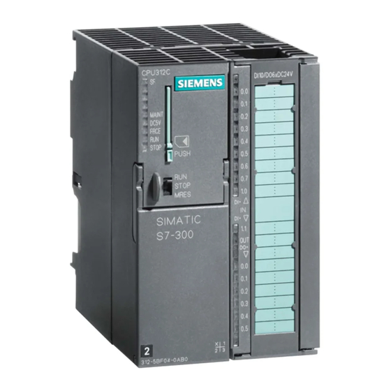
CPUs Control and Display Elements Figure 1-1 shows you the control and display elements of a CPU. The order of the elements in some CPUs might differ from the order shown in the figure below. The individual CPUs do not always have all the elements shown here. Table 1-1 shows you the differences. -
Page 19: Status And Fault Displays Of The Cpus
CPUs 1.1.1 Status and Fault Displays Displays for the CPU: SF ... (red) ...hardware/software error BATF ... (red) ...battery error (not CPU 312 IFM) DC5V ... (green) ... 5V DC supply for CPU and S7-300 bus is ok. FRCE ... (yellow) ...force job is active RUN ... -
Page 20: Mode Selector Switch
CPUs 1.1.2 Mode Selector Switch The mode selector is the same in all CPUs. Mode Selector Positions The positions of the mode selector are explained in the order in which they appear on the CPU. Details on CPU operating modes are found in the STEP 7 Online Help . Position Description Description... -
Page 21: Backup Battery/Accumulator
CPUs 1.1.3 Backup battery/accumulator Exceptions The CPUs 312IFM and 313 do not have a real time clock so they do not need an accumulator battery. The CPU 312IFM does not have a buffer which means that you can not insert a battery. -
Page 22: Memory Card
CPUs 1.1.4 Memory card Exceptions You cannot insert a memory card with the CPUs 312 IFM and 314 IFM (-5AE0x). These CPUs have an integrated read-only memory. Purpose of the Memory Card With the memory card, you can expand the load memory of your CPU. You can store the user program and the parameters that set the responses of the CPU and modules on the memory card. -
Page 23: Mpi And Profibus-Dp Interface
CPUs 1.1.5 MPI and PROFIBUS-DP Interface Table 1-4 CPU Interfaces CPU 312 IFM CPU 315-2DP CPU 318-2 CPU 313 CPU 316-2DP CPU 314IFM CPU 314 MPI interface MPI interface PROFIBUS-DP MPI/DP Interface PROFIBUS-DP interface interface MPI/ Reconfiguration as a PROFIBUS-DP interface is possible MPI interface... - Page 24 CPUs Connectable Devices PROFIBUS-DP Programming device/PC and OP Programming device/PC and OP S7 programmable controller with MPI interface S7 programmable controllers with the (S7-300, M7-300, S7-400, M7-400, C7-6xx) PROFIBUS-DP interface (S7-200, S7-300, M7-300, S7-400, M7-400, C7-6xx) S7-200 (Note: 19.2 Kbps only) Other DP masters and DP slaves Only 19.2 Kbps for S7-200 in MPI Subnet Note...
- Page 25 CPUs Loss of GD packets Following Change in the MPI Subnet During Operation Warning Loss of data packets in the MPI subnet: Connecting an additional CPU to the MPI subnet during operation can lead to loss of GD packets and to an increase in cycle time. Remedy: 1.
-
Page 26: Clock And Runtime Meter
CPUs 1.1.6 Clock and Runtime Meter Table 1-5 shows the characteristics and functions of the clock for the various CPUs. When you assign parameters to the CPU in STEP 7, you can also set functions such as synchronization and the correction factor(see the STEP 7 online help system). -
Page 27: Communication Options Of The Cpu
CPUs Behavior of Clock in POWER OFF Mode The following table shows the clock behavior with the power of the CPU off, depending on the backup: Backup CPU 314 to 318-2 CPU 312 IFM and 313 With The clock continues to operate in At POWER ON, the clock continues backup power off mode. -
Page 28: Cpu Communication Options
CPUs Table 1-6 CPU Communication Options Communications Description PG/OP Communication A CPU can maintain several on-line connections simultaneously with one or more programming devices or operator panels. For PD/OP communication via the DP interface, you must activate the “Programming, modifying and monitoring via the PROFIBUS”... - Page 29 CPUs Connection Resources Every communication connection requires a communication resource on the S7 CPU as a management unit for the duration of the communication. Every S7 CPU has a certain number of connection resources available to it according to its technical specifications which can be assigned to various communication services (PD/OP communication, S7 communication or S7 basic communication).
-
Page 30: Connection Resources For Cpus 312Ifm To 316-2 Dp
CPUs Connection Resources for CPUs 312IFM to 316-2 DP Communication resources are independent of the interface in CPUs 315-2 DP and 316-2 DP. That is, a PG communication occupies a connection resource, regardless of whether the connection was established via MPI or DP interface. Table 1-7 Connection Resources for CPUs 312 IFM to 316-2 DP Communication Function... -
Page 31: Principle Of Connection Resource Allocation For Cpu
CPUs Connection Resources for CPU 318-2 Table 1-8 Communication Resources for CPU 318-2 Communication Function Description PD/OP communication The CPU 318-2 provides a total of 32 connection resources (with CPU as connection terminal point) for these communication functions. Those 32 connection resources can be freely allocated to the various communication functions. - Page 32 CPUs Interface Resources for CPU 318-2 - Example Calculation 1. Two network transitions by routing on the CPU Resources used: - 2 connection resources of the MPI/DP interface are used; - 2 connection resources of the DP interface are used; - all 4 connection resources available to both interfaces are used;...
- Page 33 CPUs CPU 312 IFM to 316-2 DP CPU 318-2 PUT/GET functions of S7 communication, or PUT/GET functions of S7 communication, or reading/writing variables via OP reading/writing to variable via OP communication, are processed during the communication are processed in defined time cycle checkpoint of the CPU.
- Page 34 CPUs Details ... on the communication topic are found in the STEP 7 Online Help and in the manual Communication with SIMATIC..on communications SFCs/SFBs are found in the STEP 7 Online Help and in the Standard and System functions reference manual. Global Data Communication with S7-300 CPUs Below you will find important features of global data communication in the S7-300.
-
Page 35: Testing Functions And Diagnostics
CPUs Test Functions and Diagnostics The CPUs provide you with: S Testing functions for commissioning S Diagnostics via LEDs and STEP 7. 1.3.1 Testing Functions The CPUs offer you the following testing functions: S Monitor Variables S Modify Variables S Forcing (note the differences between CPUs) S Monitor block S Set Breakpoint Details on the testing functions are found in the STEP 7 Online Help. - Page 36 CPUs Different Features of Forcing S7-300 Please note the different features of forcing in the different CPUs: CPU 312IFM to 316-2DP CPU 318-2 The variables of a user program with The variables of a user program with fixed preset values (force values) fixed preset values (force values) can cannot be changed or overwritten by be changed or overwritten in the user...
-
Page 37: The Principle Of Forcing With S7-300 Cpus (Cpu 312Ifm To 316-2Dp)
CPUs Forcing with the CPU 312 IFM to 316-2 DP: Caution Forced values in the input process image can be overwritten by write instructions (e.g. T EB x, = E x.y, copying with SFC etc.) and peripheral read instructions (e.g. L PEW x) in the user program, as well as by write instructions of PG/OP opera- tions! Outputs initialized with forced values only return the forced value if the user pro-... -
Page 38: Diagnostics With Step 7
CPUs 1.3.2 Diagnostics with LED Display In Table 1-9, only the LEDs relevant to the diagnosis of the CPU and S7-300 are listed. You will find the significance of the PROFIBUS-DP interface LEDs explained in Chapter 2. Table 1-9 Diagnostic LEDs of the CPU Description Comes on in Hardware faults... - Page 39 CPUs CPU Reaction on Missing Error OB If you have not programmed an error OB, the CPU reacts as follows: CPU goes into STOP on missing ... CPU Remains in RUN with Missing ... OB 80 (Runtime error) OB 81 (Power break) OB 85 (Program cycle error)
-
Page 40: Cpus - Technical Specifications
CPUs CPUs - Technical Specifications In This Section S You will find the technical specifications of the CPU. S You will find the technical specifications of the integrated inputs/outputs of the CPU 312 IFM and 314 IFM. S You will not find the features of the CPU 31x-2 DP as a DP master/DP slave. Refer to Chapter 2. - Page 41 CPUs 1.4.1 CPU 312 IFM Special Features S Integrated I/Os (Wiring via 20-pole front connector) S No backup battery and therefore maintenance-free S An S7-300 with CPU 312 IFM can be mounted only on one rack Integrated Functions of the CPU 312 IFM Integrated Functions Description Process interrupt...
-
Page 42: Display Of The States Of The Interrupt Inputs Of The Cpu 312 Ifm
CPUs Start information for OB40 Table 1-10 shows the temporary (TEMP) variables of OB40 relevant for the “Interrupt inputs” of the CPU 312 IFM. Refer to theSystem and Standard functions reference manual for details on the process interrupt OB. Table 1-10 Start Information for OB 40 for the Interrupt Inputs of the Integrated I/Os Byte Variable Data Type... -
Page 43: Front View Of The Cpu 312 Ifm
CPUs Front View I124.0 Status and fault LEDs Mode selector I125.0 Q124.0 Front connector, Multipoint Interface used to connect (MPI) the integrated I/O, power supply and system ground. Figure 1-6 Front View of the CPU 312 IFM PLC S7-300, CPU Specifications CPU 312 IFM to CPU 318-2 DP 1-27 A5E00111190-01... - Page 44 CPUs Technical Specifications of the CPU 312 IFM CPU and Product Version Data areas and their retentive characteristics MLFB 6ES7 312-5AC02-0AB0 Retentive data area as a max. 1 DB, 72 data bytes whole (inc. flags, timers, Hardware version counters) Firmware version V 1.1.0 Bit memories 1024...
- Page 45 CPUs Configuration Communication functions Rack PD/OP communication Modules per module rack max. 8 Global data communication DP Master Number of GD packets integral None – Sender via CP – Receiver S7 message functions Size of GD packets max. 22 bytes Simultaneously active None –...
- Page 46 CPUs Voltages, Currents Services Power supply 24V DC – PD/OP Permissible range 20.4 to 28.8 V communication Current consumption (idle) typical 0.7 A – Global data Inrush current typical 8A communication 0.4 A – S7 basic communication External fusing for supply Circuit breaker;...
- Page 47 CPUs Technical Specifications of the Special Inputs of the CPU 312IFM Module-Specific Data Sensor Selection Data Number of inputs Input voltage I 124.6 to 125.1 Rated value 24V DC Cable length For “1” signal I 125.0 and I 125.1 15 to 30 V Shielded max.
- Page 48 CPUs Technical Specifications of the Digital Inputs of the CPU 312IFM Note Alternatively, you can configure the inputs I 124.6 and I 124.7 as special inputs, in which case the technical specifications listed for the special inputs apply to the inputs I 124.6 and I 124.7.
- Page 49 CPUs Technical Specifications of the Digital Outputs of the CPU 312IFM Module-Specific Data Actuator Selection Data Number of outputs Output voltage For “1” signal min. L+ (-0.8 V) Cable length Unshielded max. 600 m Output current For “1” signal Shielded max.
-
Page 50: Wiring Diagram Of The Cpu 312 Ifm
CPUs Wiring diagram of the CPU 312 IFM Figure 1-7 shows the wiring diagram of the CPU 312 IFM. Use a 20-pole front connector to wire the CPU’s integrated I/O. Caution The CPU 312 IFM has no reverse polarity protection. Polarity reversal destroys the integrated outputs. - Page 51 CPUs Power Supply Connections CPU 312 IFM and S the integrated I/Os are connected to power at the terminals 18 and 19 (see Figure 1-7). Short-circuit reaction On short-circuit at one of the integrated outputs of CPU 312 IFM, proceed as follows: 1.
-
Page 52: Basic Circuit Diagram Of The Cpu 312 Ifm
CPUs Basic Circuit Diagram of the CPU 312 IFM Figure 1-8 shows the block diagram of CPU 312 IFM. CPU power supply Figure 1-8 Basic Circuit Diagram of the CPU 312 IFM PLC S7-300, CPU Specifications CPU 312 IFM to CPU 318-2 DP 1-36 A5E00111190-01... -
Page 53: Cpu 313
CPUs 1.4.2 CPU 313 Technical Specifications of the CPU 313 CPU and Product Version Data areas and their retentive characteristics MLFB 6ES7 313-1AD03-0AB0 Retentive data area as a max. 1 DB, 72 data bytes whole (inc. flags, timers, Hardware version counters) Firmware version V 1.1.0... - Page 54 CPUs Configuration Communication functions Rack PD/OP communication Modules per module rack max. 8 Global data communication Number of DP masters Number of GD packets integral – Sender via CP – Receiver S7 message functions Size of GD packets max. 22 bytes Simultaneously active None –...
- Page 55 CPUs Voltages, Currents Services Power supply 24V DC – PD/OP Permissible range 20.4 to 28.8 communication Current consumption (idle) typical 0.7 A – Global data Inrush current typical 8A communication 0.4 A – S7 basic communication External fusing for supply Circuit breaker;...
-
Page 56: Cpu 314
CPUs 1.4.3 CPU 314 Technical Specifications of the CPU 314 CPU and Product Version Data areas and their retentive characteristics MLFB 6ES7 314-1AE04-0AB0 Retentive data area as a 4736 bytes whole (inc. flags, timers, Hardware version counters) Firmware version V 1.1.0 Bit memories 2048 Matching programming... - Page 57 CPUs Configuration Communication functions Rack max. 4 PD/OP communication Modules per module rack max. 8 Global data communication Number of DP masters Number of GD packets integral None – Sender via CP – Receiver S7 message functions Size of GD packets max.
- Page 58 CPUs Voltages, Currents Services Power supply 24V DC – PD/OP Permissible range 20.4 V to 28.8 V communication Current consumption (idle) typical 0.7 A – Global data Inrush current typical 8A communication 0.4 A – S7 basic communication External fusing for supply Circuit breaker;...
-
Page 59: Cpu 314Ifm
CPUs 1.4.4 CPU 314IFM Special Features S Integrated I/Os (wired with 40-pole front connector) Details on analog value processing and how to connect measuring transducers, load and actuators to analog I/O is found in the Module Data reference manual. Figures 1-14 and 1-15 on page 1-59 show wiring examples. Memory card The CPU 314 IFM is available in 2 versions: with and without Memory Card slot. -
Page 60: Start Information For Ob 40 For The Interrupt Inputs Of The Integrated I/Os
CPUs “Interrupt Inputs” of the CPU 314 IFM If you want to assign interrupt functions to the digital inputs 126.0 to 126.4, configure your CPU parameters in STEP 7 accordingly. Note the following points: These digital inputs have a very low signal delay. At this interrupt input, the module recognizes pulses with a length as of approx. -
Page 61: Display Of The States Of The Interrupt Inputs Of The Cpu 314 Ifm
CPUs Display of the Interrupt Inputs In variable OB40_POINT_ADDR, you can view the interrupt inputs which have triggered a process interrupt. Figure 1-9 shows the allocation of the interrupt inputs to the bits of the double word. Note: Several bits can be set if interrupts are triggered by several inputs within short intervals (<... -
Page 62: Front View Of The Cpu 314 Ifm
CPUs Front View of the CPU 314 IFM ³ À Á Â Ã Ä Æ Å À Ä Connection for power supply and system ground Status and error LEDs Á Mode selector switch Å Multipoint interface MPI Â Æ Integrated I/Os Compartment for backup battery or Ç... - Page 63 CPUs Technical Specifications of the CPU 314 IFM CPU and Product Version Data areas and their retentive characteristics MLFB 6ES7 314-...-0AB0 -5AE03- -5AE10- Retentive data area as a max. 2 DB, 144 bytes whole (inc. flags, timers, Hardware version counters) Firmware version V 1.1.0 V 1.1.0...
- Page 64 CPUs Configuration Communication functions Rack max. 4 PD/OP communication Modules per module rack max. 8; max. 7 in module Global data communication rack 3 Number of GD packets Number of DP masters – Sender integral None – Receiver via CP Size of GD packets max.
- Page 65 CPUs PD supply at MPI (15 to max. 200 mA 30V DC) Services Power losses Typically 16 W – PD/OP communication Battery – Global data Backup margin at 25_ min. 1 year communication C and continuous CPU buffering – S7 basic communication Battery shelf life at approx.
-
Page 66: Characteristic Features Of The Integrated Inputs And Outputs
CPUs Characteristic Features of the Integrated Inputs and Outputs of the CPU 314 IFM Table 1-12 Characteristic Features of the Integrated Inputs and Outputs of the CPU 314 IFM Inputs/Outputs Characteristics Voltage inputs ""10 V Analog inputs All information required for Current inputs ""20 mA analog value display, as well as Resolution 11 bits + sign bit... - Page 67 CPUs Technical Specifications of the Analog Inputs of the CPU 314IFM Module-Specific Data Interference Suppression, Error Limits, Conti- nued Number of inputs Basic error limits Cable length (operational limit at 25°C, Shielded max. 100 m (109yd.) relative to input range) Voltage input Voltages, Currents, Potentials "...
- Page 68 CPUs Technical Specifications of the Analog Output of the CPU 314IFM " 0.05 % Module-Specific Data Output ripple; Range of 0 to 50 kHz (referring to output Number of outputs range) Cable length Status, Interrupts; Diagnostics Shielded max. 100 m (109yd.) Interrupts None Voltages, Currents, Potentials...
- Page 69 CPUs Technical Specifications of the Special Inputs of the CPU 314IFM Module-Specific Data Sensor Selection Data Number of inputs Input voltage I 126.0 to 126.3 Rated value 24V DC Cable length For “1” signal 11 V to 30 V 18 to 30 V with Shielded max.
- Page 70 CPUs Technical Specifications of the Digital Inputs of the CPU 314IFM Module-Specific Data Status, Interrupts; Diagnostics Number of inputs Status display 1 green LED per channel Cable length Interrupts None Unshielded max. 600 m Shielded max. 1000 m Diagnostic functions None Voltages, Currents, Potentials Sensor Selection Data...
- Page 71 CPUs Technical Specifications of the Digital Outputs of the CPU 314IFM Remarks When the supply voltage is switched on a pulse occurs on the digital outputs! This can be 50 ms long within the permissible output current range. You must not, therefore, use the digital outputs to trigger high-speed counters.
-
Page 72: Wiring Diagram Of The Cpu 314 Ifm
CPUs Wiring diagram of the CPU 314 IFM Figure 1-11 shows the wiring diagram of the CPU 314 IFM. For the connection of integrated I/O you require two 40-pole front connectors (Order no.: 6ES7392-1AM00-0AA0). Always wire up digital inputs 126.0 to 126.3 with shielded cable due to their low input delay time. -
Page 73: Basic Circuit Diagram Of The Cpu 314 Ifm
CPUs Basic Circuit Diagrams of the CPU 314 IFM Figures 1-12 and 1-13 show the basic circuit diagrams for the integrated inputs/outputs of the CPU 314 IFM. Multiplexer Internal supply Figure 1-12 Basic Circuit Diagram of the CPU 314 IFM (Special Inputs and Analog Inputs/Outputs) PLC S7-300, CPU Specifications CPU 312 IFM to CPU 318-2 DP 1-57 A5E00111190-01... -
Page 74: Basic Circuit Diagram Of The Cpu 314 Ifm (Digital Inputs/Outputs)
CPUs 1 L+ interface Figure 1-13 Basic Circuit Diagram of the CPU 314 IFM (Digital Inputs/Outputs) PLC S7-300, CPU Specifications CPU 312 IFM to CPU 318-2 DP 1-58 A5E00111190-01... -
Page 75: Connecting 2-Wire Measurement Transducers To The Analog Inputs
CPUs Wiring the Analog Inputs 1 L+ 2-wire measurement transducer AI_ and M - we recommend to jumper them. Figure 1-14 Connecting 2-wire measurement transducers to the analog inputs of CPU 314 IFM 1 L+ Shielded cables 4-wire measurement transducer Unwired channel groups: Connect AI_ with M When using 4-wire measurement transducers,... -
Page 76: Cpu 315
CPUs 1.4.5 CPU 315 Technical Specifications of the CPU 315 CPU and Product Version Data areas and their retentive characteristics MLFB 6ES7 315-5AF03-0AB0 Retentive data area as a 4736 bytes whole (inc. flags, timers, Hardware version counters) Firmware version V 1.1.0 Bit memories 2048 Matching programming... - Page 77 CPUs Configuration Communication functions Rack max. 4 PD/OP communication Modules per module rack max. 8 Global data communication Number of DP masters Number of GD packets integral None – Sender via CP – Receiver S7 message functions Size of GD packets max.
- Page 78 CPUs Voltages, Currents Services Power supply 24V DC – PD/OP Permissible range 20.4 to 28.8 V communication Current consumption (idle) typical 7.0 A – Global data Inrush current typical 8A communication 0.4 A – S7 basic communication External fusing for supply Circuit breaker;...
-
Page 79: Cpu 315-2 Dp
CPUs 1.4.6 CPU 315-2 DP DP master or DP slave You can operate the CPU 315-2 DP on your 2nd interface (PROFIBUS-DP interface) as DP Master or DP Slave in a PROFIBUS-DP network. For details on PROFIBUS-DP characteristics of CPU 315-2 DP refer to Chapter 2. CPU 315-2 DP, Technical Data CPU and Product Version S7 timers... - Page 80 CPUs Address areas (I/O) Single sequence Breakpoint Peripheral address area, 1 KB/1 KB (freely digital/analog addressable)of these are Diagnostic buffer distributed 1 KB/1 KB Number of entries (non-alterable) Process image (cannot be 128/128 bytes customized) Communication functions Digital channels max. 8192 (minus 1 byte PD/OP communication diagnostic address per DP Global data communication...
- Page 81 CPUs Interfaces DP Slave Services 1. Interface – Status/Modify; Yes, can be activated Functionality Program via PROFIBUS Routing DP Master Device master file Sie3802f.gsg DP Slave Transmission rate ... up to 12 Mbps Galvanically isolated Transfer memory 244 bytes I/244 bytes O –...
-
Page 82: Cpu 316-2 Dp
CPUs 1.4.7 CPU 316-2 DP DP master or DP slave You can operate the CPU 316-2 DP on your 2nd interface (PROFIBUS-DP interface) as DP Master or DP Slave in a PROFIBUS-DP network. For details on PROFIBUS-DP characteristics of CPU 316-2 DP refer to Chapter 2. CPU 316-2 DP, Technical Data CPU and Product Version S7 timers... - Page 83 CPUs Address areas (I/O) Monitor block Peripheral address area, 2 KB/2 KB (freely Single sequence digital/analog addressable) Breakpoint Distributed 2 KB/2 KB Diagnostic buffer Process image (cannot be 128/128 bytes Number of entries customized) (non-alterable) Digital channels max. 16384 (minus 1 byte Communication functions diagnostic address per DP PD/OP communication...
- Page 84 CPUs Interfaces DP Slave 1. Interface Services Functionality – Status/Modify; Yes, can be activated Program; Routing Device master file Siem806f.gsg DP Master Transmission rate Up to 12 Mbps DP Slave Transfer memory 244 bytes I/244 bytes O Galvanically isolated – Address areas max.
- Page 85 CPUs 1.4.8 CPU 318-2 Special Features S 4 accumulators S The configuration of MPI interfaces can be changed: MPI or PROFIBUS DP (DP Master). S Configurable data areas (Process image, local data) Information on differences between CPU 318-2 and other CPUs is found in Chapter 4.1.
- Page 86 CPUs FM 353/354, distributed If you implement the CPU 318-2 as DP Master, you can operate FM 353 as of 6ES7 353-1AH01-0AE0, firmware version 3.4/03 and FM 354 as of 6ES7 354-1AH01-0AE0, firmware version 3.4/03 in distributed mode with an ET 200M. You cannot operate the following modules in an S7-300 equipped with a 318-2 FM 357 up to 6ES7 357-4_H02-3AE_, firmware version 2.1;...
-
Page 87: Cpu 318-2
CPUs CPU 318-2, Technical Data CPU and Product Version Data areas and their retentive characteristics MLFB 6ES7 318-2AJ00-0AB0 Retentive data area as a max. 11 KB whole (inc. flags, timers, Hardware version counters) Firmware version V 3.0 Bit memories 8192 Matching programming STEP 7 V 5.1 + Adjustable retentivity... - Page 88 CPUs Configuration – Number of which 32 bytes consistent Rack max. 4 S7 basic communication Modules per module rack max. 8 User data per job max. 76 bytes Number of DP masters – Number of which 76 bytes integral consistent via CP S7 communication Yes (server)
- Page 89 CPUs DP Master DP Slave Services Services – Status/Modify; Yes, can be activated – Equidistance Program; – SYNC/FREEZE Routing – Activation/deactivat GSD file siem807f.gsg ion of DP slaves Transmission speed Up to 12 Mbps Transmission rates Up to 12 Mbps Transfer memory Address area max.
- Page 90 CPUs PLC S7-300, CPU Specifications CPU 312 IFM to CPU 318-2 DP 1-74 A5E00111190-01...
-
Page 91: Cpu 31X-2 As Dp Master/Dp Slave And Direct Communication
CPU 31x-2 as DP Master/DP Slave and Direct Communication Introduction In this chapter you will find the features and technical specifications of the CPUs 315-2 DP, 316-2DP and 318-2. You will need these in order to use the CPU as a DP master or a DP slave and configure it for direct communication. - Page 92 CPU 31x-2 as DP Master/DP Slave and Direct Communication Information on DPV1 Functionality The aim The EN50170 Standard for Distributed Peripherals was subject to further development. All changes were incorporated in IEC 61158 / EN 50170, Volume 2, PROFIBUS. In order to simplify matters we now refer to DPV1 Mode.
- Page 93 Can I use DPV1 Slaves without this migration? Yes, without restriction. In this case, DPV1 Slaves behave as conventional Slaves. SIEMENS DPV1 Slaves can also be operated in S7 compatible mode. For DPV1 Slaves of other manufacturers you require a GSD file to EN50170 below Revision 3.
- Page 94 CPU 31x-2 as DP Master/DP Slave and Direct Communication DP Address Areas of the CPUs 31x-2 Address areas of CPUs 31x-2 Address area 315-2 DP 316-2DP 318-2 DP address area 1024 bytes 2048 bytes 8192 bytes for I/Os of these in the I/O Bytes 0 to 127 Bytes 0 to 127 Bytes 0 to 255...
- Page 95 CPU 31x-2 as DP Master/DP Slave and Direct Communication CPU 31x-2 as DP Master Introduction This section covers the features and technical specifications of the CPU when it is used as a DP master. The features and technical specifications of the CPU 31x-2 as the “standard” CPU are listed in Section 1.
-
Page 96: Meaning Of The Busf Led Of The Cpu 31X-2 As Dp Master
CPU 31x-2 as DP Master/DP Slave and Direct Communication Power-Up of the DP Master System CPU 31x-2DP is DP Master CPU 318-2 is DP Master You can also set power-up time monitoring Using the parameters of the DP slaves with the “Transfer of parameters to modules”... -
Page 97: Reading Diagnostic Data With Step 7
CPU 31x-2 as DP Master/DP Slave and Direct Communication Reading Diagnostic Data with STEP 7 Table 2-2 Reading Diagnostic Data with STEP 7 DP Master Modules or Application See... registers in STEP 7 CPU 31x-2 ”DP slave Display slave diagnostic data See “Diagnosis of Hardware”... -
Page 98: Diagnostics With Cpu 315-2Dp < 315-2Af03
CPU 31x-2 as DP Master/DP Slave and Direct Communication CPU 315-2DP smaller than 6ES7 315-2AF03-0AB0 Diagnostic event OB82 is called Read out the parameter OB 82_MDL_TYPE in the local data of OB 82: The module class is in the bits 0 to 3 (DP slave type) 1011 = 0011 =... -
Page 99: Diagnostics With Cpu 31X-2 (315-2Dp As Of 315-2Af03)
CPU 31x-2 as DP Master/DP Slave and Direct Communication CPU 315-2DP as of 6ES7 315-2AF03-0AB0 CPU 3162DP; Diagnostic event 318-2 OB82 is called only 318-2 Read out OB82_MDL_ADDR For the diagnostics of the respective modules: Read out OB82_IO_FLAG call SFB 54 (in DPV1 mode) (= identifier I/O module) ±... -
Page 100: Diagnostic Addresses For Dp Master And Dp Slave
CPU 31x-2 as DP Master/DP Slave and Direct Communication Diagnostic Addresses With a CPU 31x-2, you assign the diagnostic addresses for the PROFIBUS-DP. Make sure during configuration that DP diagnostic addresses are assigned to both the DP master and the DP slave. CPU 31x-2 as DP Master CPU 31x-2 as DP Slave PROFIBUS... -
Page 101: Event Detection Of The Cpu 31X-2 As Dp Master
CPU 31x-2 as DP Master/DP Slave and Direct Communication Event Detection Table 2-3 shows how a DP Master CPU 31x-2 recognizes operating state transitions of a DP Slave CPU or or data transfer interrupts. Table 2-3 Event Detection of the CPU 31x-2 as DP Master Event What Happens in the DP Master Bus interruption... -
Page 102: Evaluating Run-Stop Transitions Of The Dp Slaves In The Dp Master
CPU 31x-2 as DP Master/DP Slave and Direct Communication Evaluation in the User Program Table 2-4 shows you how you can, for example, evaluate RUN-STOP transitions of the DP slave in the DP master (see Table 2-3). Table 2-4 Evaluating RUN-STOP Transitions of the DP Slaves in the DP Master In the DP Master In the DP Slave (CPU 31x-2DP) Diagnostic Addresses Example:... - Page 103 If you are working with an older version or another configuration tool, you can get the device master file from the following sources: S On the Internet at http://www.ad.siemens.de/csi_e/gsd S Via modem from the SSC (Interface Center) Fuerth by calling 0911/911/737972.
-
Page 104: Transfer Memory In A Cpu 31X-2 Operating As Dp Slave
CPU 31x-2 as DP Master/DP Slave and Direct Communication Status/Control, Programming via PROFIBUS As an alternative to the MPI interface, you can program the CPU via PROFIBUS-DP interface or execute the PG’s Status and Control functions . To do so, you must enable these functions when configuring the CPU as a DP slave in STEP 7. -
Page 105: Example Of An Address Area Configuration For Transfer Memory
CPU 31x-2 as DP Master/DP Slave and Direct Communication Address areas of the transfer memory Configure the I/O address areas in STEP 7: S you can configure up to 32 I/O address areas S the maximum length of each one of these address areas is 32 bytes S You can configure a maximum of 244 bytes for inputs and 244 bytes for outputs. - Page 106 CPU 31x-2 as DP Master/DP Slave and Direct Communication S5 DP Master If you are using an IM 308 C as a DP master and the CPU 31x-2 as a DP slave, the exchange of consistent data requires the following: In the IM 308 C, you must program FB 192 to enable the exchange of consistent data between DP master and DP slave.
- Page 107 CPU 31x-2 as DP Master/DP Slave and Direct Communication Sample Program Below you will see a small sample program for the exchange of data between DP master and DP slave. The addresses used in the example are those from Table 2-5.
-
Page 108: Diagnosis Of The Cpu 31X-2 Operating As Dp-Slave
CPU 31x-2 as DP Master/DP Slave and Direct Communication Diagnosis of the CPU 31x-2 operating as DP-Slave In This Section Section Contents Page 2.6.1 Diagnosis with LEDs 2-19 2.6.2 Diagnostics with STEP 5 or STEP 7 2-19 2.6.3 Reading Out the Diagnostic Data 2-20 2.6.4 Format of the Slave Diagnostic Data... -
Page 109: Meaning Of The Busf Leds In The Cpu 31X-2 As Dp Slave
CPU 31x-2 as DP Master/DP Slave and Direct Communication 2.6.1 Diagnosis with LEDs Diagnostics with LED displays - CPU 31x-2 Table 2-6 explains the meaning of the BUSF LEDs. The BUSF LED assigned to the interface configured as the PROFIBUS-DP interface will always come on or flash. -
Page 110: Fetching Diagnostic Data With Step 5 And Step 7 In The Master System
CPU 31x-2 as DP Master/DP Slave and Direct Communication S7 Diagnosis An S7 diagnosis can be requested for all the modules in the SIMATIC S7/M7 range of modules in the user program. The structure of the S7 diagnostic data is the same for both central and distributed modules. - Page 111 CPU 31x-2 as DP Master/DP Slave and Direct Communication Example of fetching Slave diagnostic data with FB192 “IM 308C” Here you will find an example of how to use FB192 to fetch slave diagnostic data of a DP slave in the 192 STEP 5 user program. Assumptions The following assumptions are made for this STEP 5 user program: S IM 308-C, operating as DP Master, occupies frames 0 ...
-
Page 112: Diagnostic Addresses For Dp Master And Dp Slave
CPU 31x-2 as DP Master/DP Slave and Direct Communication STEP 7 User Program Description CALL SFC 59 :=TRUE Request to Read IOID :=B#16#54 Identifier of the Address Area, here the I/O input LADDR :=W#16#200 Logical address of the module RECNUM :=B#16#1 Data record 1 is to be read out RET_VAL := Errors result in the output of an error code... -
Page 113: Event Detection Of The Cpu 31X-2 As Dp Slave
CPU 31x-2 as DP Master/DP Slave and Direct Communication Event Detection Table 2-8 shows how a DP Master CPU 31x-2 recognizes operating state transitions of a DP Slave CPU or or data transfer interrupts. Table 2-8 Event Detection of the CPU 31x-2 as DP Slave Event What Happens in the DP Slave Bus interruption... -
Page 114: Format Of The Slave Diagnostic Data
CPU 31x-2 as DP Master/DP Slave and Direct Communication 2.6.4 Format of the Slave Diagnostic Data Structure of Slave Diagnostics Byte 0 Byte 1 Station Status 1 to 3 Byte 2 Byte 3 Master PROFIBUS Address High byte Byte 4 Manufacturer Byte 5 Low byte... -
Page 115: Structure Of Station Status 1 (Byte 0)
CPU 31x-2 as DP Master/DP Slave and Direct Communication 2.6.5 Station Status 1 to 3 Definition Station status 1 to 3 provides an overview of the status of a DP slave. Station Status 1 Table 2-10 Structure of Station Status 1 (Byte 0) Description Remedy 1: DP slave cannot be addressed by... -
Page 116: Structure Of Station Status 2 (Byte 1)
CPU 31x-2 as DP Master/DP Slave and Direct Communication Station Status 2 Table 2-11 Structure of Station Status 2 (Byte 1) Meaning 1: New parameter assignment and configuration of the DP Slave is required. 1: A diagnostic message has arrived. The DP slave cannot continue operation until the error has been rectified (static diagnostic message). -
Page 117: Structure Of The Master Profibus Address (Byte 3)
CPU 31x-2 as DP Master/DP Slave and Direct Communication 2.6.6 Master PROFIBUS Address Definition The DP address of the DP Master is written to the diagnostic byte Master PROFIBUS address: S The master that has configured the DP slave S The master that has read and write access to the DP slave Master PROFIBUS Address Table 2-13 Structure of the Master PROFIBUS Address (Byte 3) Description... -
Page 118: Structure Of The Module Diagnosis Of The Cpu 31X-2
CPU 31x-2 as DP Master/DP Slave and Direct Communication 2.6.8 Module Diagnostics Definition ID related diagnostics specifies in which one of the configured address areas of transient memory an entry was made. 0 Bit No. Byte 6 Length of ID-related diagnostic data incl. -
Page 119: Structure Of The Station Diagnosis
CPU 31x-2 as DP Master/DP Slave and Direct Communication 2.6.9 Station Diagnostics Definition Device diagnostics provides details on a DP Slave. The station diagnosis begins as of byte x and can have a maximum of 20 bytes. Station Diagnostics The figure below describes the structure and content of the bytes for a configured address area in transfer memory. -
Page 120: Byte X +4 To X +7 For Diagnostic And Hardware Interrupt
CPU 31x-2 as DP Master/DP Slave and Direct Communication As of byte x +4 The purpose of the bytes beginning with byte x+4 depends on byte x+1 (see Figure 2-8). Byte x+1 Contains the Code for... Diagnostic Interrupt (01 Hardware interrupt (02 The diagnostic data contains the 16 bytes of You can freely program 4 interrupt information status information from the CPU. -
Page 121: Interrupts
CPU 31x-2 as DP Master/DP Slave and Direct Communication 2.6.10 Interrupts Interrupts with S7/M7 DP Master You can trigger a process interrupt at the DP Master in the user program of a CPU 31x-2 operating as DP Slave. A call of SFC 7 “DP_PRAL” triggers an OB40 in the user program of the DP Master. -
Page 122: Direct Communication Using Cpu 31X-2
CPU 31x-2 as DP Master/DP Slave and Direct Communication Direct Data Exchange As of STEP 7 V 5.x you can configure “Direct Data Exchange” for your PROFIBUS nodes. The CPU 31x-2 can take part in direct communication as the sender or receiver. -
Page 123: Diagnostic Address For Receiver With Direct Communication
CPU 31x-2 as DP Master/DP Slave and Direct Communication Diagnosis with Direct Communication Diagnostic Addresses With direct communication you allocate a diagnostic address on the receiver: CPU 31x-2 as Sender CPU 31x-2 as Receiver PROFIBUS Diagnostic address During configuration you define in the receiver a diagnostic address that is allocated to the sender. -
Page 124: Evaluation Of The Station Failure Of The Sender During
CPU 31x-2 as DP Master/DP Slave and Direct Communication Evaluation in the User Program Table 2-16 shows you how you can, for example, evaluate the station failure of the sender in the receiver (see also Table 2-15). Table 2-16 Evaluation of the Station Failure of the Sender During Direct Communication In the Sender In the Receiver Diagnostic Addresses Example:<FJ>... - Page 125 Cycle and Reaction times Introduction In this section, we explain what the cycle time and the response time of the S7-300 consist of. You can use the programming device to read the cycle time of your user program (see the STEP 7 online help system). The example below shows you how to calculate the cycle time.
-
Page 126: Component Parts Of The Cycle Time
Cycle and Reaction times Cycle time Cycle Time – A Definition The cycle time is the time that elapses during one program cycle. Component Parts of the Cycle Time The cycle time comprises: Factors Remarks Operating system execution time See Section 3.2 Process image transfer time (PII and PIO) User program execution time... -
Page 127: Response Time
Cycle and Reaction times Extending the Cycle Time Note that the cycle time of a user program is extended by the following: S Time-controlled interrupt handling S process interrupt processing (also refer to Chapter 3.4) S Diagnostics and error handling (see also Section 3.4) S Communication via MPI Response Time Response Time –... -
Page 128: Shortest Response Time
Cycle and Reaction times Shortest Response Time Figure 3-2 shows you the conditions under which the shortest response time is reached. Delay of the inputs The status of the observed input changes immediately before reading in the PII. The change in the input signal is therefore taken account of in the PII. -
Page 129: Longest Response Time
Cycle and Reaction times Longest Response Time Figure 3-3 shows the conditions that result in the longest response time. Delay of the inputs + bus runtime on the PROFIBUS-DP While the PII is being read in, the status of the observed input changes. The change in the input signal is no longer taken into account in the PII. -
Page 130: Operating System Processing Times Of The Cpus
Cycle and Reaction times Calculation The (longest) response time consists of the following: Process image transfer time of inputs + Process image transfer time of outputs + Operating system execution time+ program execution time+ Bus runtime on the PROFIBUS-DP bus system (with CPU 31x-2 DP) S Execution time of the S7 timer+ S Delay of the inputs and outputs This corresponds to the sum of the double cycle time and the delay of the inputs... -
Page 131: Process Image Update Of The Cpus
Cycle and Reaction times Table 3-2 Process image update of the CPUs Components 316-2 318-2 315-2 K Base load 162ms 142ms 142ms 147ms 109ms 10ms 10ms 20ms 6 ms A For each byte in rack 14.5ms 13.3ms 13.3ms 13.6ms 10.6ms 20ms 20ms “0”... -
Page 132: Update Time And Sfb Runtimes
Cycle and Reaction times PROFIBUS-DP interface In the case of the CPU 315-2 DP/316-2DP, the cycle time is typically extended by 5% when the PROFIBUS-DP interface is used. In the case of the CPU 318-2, there is no increase in cycle time when the PROFIBUS-DP interface is used. -
Page 133: Overview Of The Bus Runtime On Profibus-Dp At 1.5 Mbps
Cycle and Reaction times Bus Runtimes in the PROFIBUS Subnet If you have used STEP 7 to configure your PROFIBUS subnet, STEP 7 calculates the expected normal bus cycle time. On the PG you can then view the bus cycle time of your configuration (refer to the STEP 7 User Manual). -
Page 134: Extending The Cycle By Nesting Interrupts
Cycle and Reaction times Extending the Cycle by Nesting Interrupts Table 3-6 shows typical extensions of the cycle time through nesting of an interrupt. The program runtime at the interrupt level must be added to these. If several interrupts are nested, the corresponding times need to be added. Table 3-6 Extending the Cycle by Nesting Interrupts Interrupts... - Page 135 Cycle and Reaction times Sample Configuration 1 You have configured an S7-300 with the following modules on one rack: S 1 CPU 314 S 2 SM 321 DI 32DC 24 V digital input modules (4 bytes each in the PI) S 2 SM 322 DO 32 DC 24 V/0.5A (4 bytes each in the PI) According to the Instruction List, the user program has a runtime of 1.5 ms.
- Page 136 Cycle and Reaction times Parts of the Response Time As a reminder, the response time is formed by the sum of: Process image transfer time of inputs + Process image transfer time of outputs + operating system cycle time+ program cycle time+ S Processing time of the S7 timers + S Delay times of the inputs and outputs Tip: Simple calculation: calculated cycle time...
- Page 137 Cycle and Reaction times S 1. Intermediate calculation: Timebase for the calculation of S7 timer processing time is the sum of all times mentioned above: 2 0.36 ms (Input process image transfer time) + 2 0.23 ms (Output process image transfer time) + 2 1 ms (Operating system cycle time) User program cycle time) [7.8 ms.
-
Page 138: Response Time Of The Cpus To Process Interrupts
Cycle and Reaction times Interrupt response time Interrupt Response Time – A Definition The interrupt response time is the time that elapses between the first occurrence of an interrupt signal and the calling of the first instruction in the interrupt OB. Generally valid is: High-priority interrupts are preferred. -
Page 139: Diagnostic Interrupt Response Times Of The Cpus
Cycle and Reaction times Diagnostic Interrupt Response Times of the CPUs Table 3-8 lists the diagnostic interrupt response times of the CPUs (without communication). Table 3-8 Diagnostic Interrupt Response Times of the CPUs Min. Max. 312 IFM – – 0.6 ms 1.3 ms 0.6 ms 1.3 ms... -
Page 140: Calculation Example For The Interrupt Response Time
Cycle and Reaction times Calculation Example for the Interrupt Response Time Parts of the Interrupt Response Time As a reminder: The process interrupt response time is formed by: S Response time of the CPU to process interrupt and S the response time of the signal module to process interrupt. Example: Your S7-300 assembly consists of a CPU 314 and four digital modules. -
Page 141: Reproducibility Of The Delay And Watchdog Interrupts Of The Cpus
Cycle and Reaction times Reproducibility Table 3-9 lists reproducibility of the delay and watchdog interrupts of the CPUs (without communication). Table 3-9 Reproducibility of the Delay and Watchdog Interrupts of the CPUs Reproducibility Delay Interrupt Watchdog Interrupt approx. $0.2 ms approx. - Page 142 Cycle and Reaction times PLC S7-300, CPU Specifications CPU 312 IFM to CPU 318-2 DP 3-18 A5E00111190-01...
- Page 143 CPU Function, depending on CPU and STEP 7 Version In this chapter we describe the functional differences between the various CPU versions. These differences are determined by S CPU performance characteristics (especially CPU 318-2) compared to other CPUs the functionaliy of CPUs described in this manual in comparison to previous versions.
-
Page 144: Differences Between Cpu 3182 And Cpus 312 Ifm To 3162 Dp
CPU Function, depending on CPU and STEP 7 Version Differences between CPU 3182 and CPUs 312 IFM to 3162 DP 4 rechargeable batteries for 318-2 CPU 318-2 CPUs 312IFM to 316-2DP 4 accumulators 2 accumulators The following table shows you what to watch for if you want to use an STL user program of a CPU 312IFM to a CPU 316-2DP for the CPU 318-2. - Page 145 CPU Function, depending on CPU and STEP 7 Version System ID (only CPU 318-2) In the object properties of the ”General” tab, you can assign a system ID when configuring your CPU. This ID can be evaluated in the CPU user program (also refer to the STEP 7 Online Help relating to the “General”...
-
Page 146: Sample Configuration
CPU Function, depending on CPU and STEP 7 Version S7-300 The CPU 316 is replaced with a CPU 318-2 S7-300 S7-300 with CPU 316 S7-300 OP 25 OP 25 RS 485 repeater Figure 4-1 Sample Configuration After the CPUs have been swapped, you must proceed as follows (based on the above example): S Replace the CPU 316 with the CPU 318-2 in the STEP 7 project. - Page 147 CPU Function, depending on CPU and STEP 7 Version Connection resources CPU 318-2 CPUs 312IFM to 316-2DP CPU 318-2 provides a total of 32 The CPUs provide a specific number of communication resources, that is, 32 of connection resources. those via MPI/DP interface or 16 via DP interface.
-
Page 148: Memory Cards
CPU Function, depending on CPU and STEP 7 Version The Differences Between the CPUs 312 IFM to 318 and Their Previous Versions Memory Cards and Backing Up Firmware on Memory Card As of the following CPUs: Order No. As of Version Firmware Hardware CPU 313... - Page 149 CPU Function, depending on CPU and STEP 7 Version MPI Addressing You Have a CPU as of Order Number and Your CPU version and order number is lower than the following: Version: 6ES7312-5AC01-0AB0, version 01 6ES7313-1AD02-0AB0, version 01 6ES7314-1AE03-0AB0, version 01 6ES7314-5AE02-0AB0, version 01 6ES7315-1AF02-0AB0, version 01 6ES7315-2AF02-0AB0, version 01...
- Page 150 CPU Function, depending on CPU and STEP 7 Version CPU 315-2 DP v 6ES7 315-2AF03-0AB0 CPU 315-2 DP as of 6ES7 and STEP 7 < V 5.x 315-2AF03-0AB0 and STEP 7 as of V 5.x Direct communication Equidistance Activation/deactivation of DP slaves Routing Reading out of slave...
- Page 151 CPU Function, depending on CPU and STEP 7 Version New SFBs and SFCs in CPU 318-2 Function Application Execution time See... in ms Block SFB 52 Fetching data records to a DP Slave Initial call Online help Standard Intermediate call 111 Final call System SFB 53...
- Page 152 CPU Function, depending on CPU and STEP 7 Version Function Application Execution time See... in ms Block SFC 100* Setting TOD and TOD Status MODE 1 Online help Standard MODE 2 MODE 3 System- functions in STEP 7 SFC 105* Reading dynamic system MODE 0 117-1832...
- Page 153 CPU Function, depending on CPU and STEP 7 Version Description of Diverse SFB Execution Times The BUSY output parameter indicates the current job status. Initial call: Job starts with the execution, d. h. BUSY status is toggled from 0 to 1. Intermediate call: The job is being executed, d.
- Page 154 CPU Function, depending on CPU and STEP 7 Version PLC S7-300, CPU Specifications CPU 312 IFM to CPU 318-2 DP 4-12 A5E00111190-01...
- Page 155 Tips and Tricks Tip on the Parameter “Monitoring time for ...” in STEP 7 Configure the parameters for “Monitoring time S for parameter download to module” S ready message by module” the highest values if you are not certain of the times required on the S7-300. CPU 31x-2DP is DP Master CPU 318-2 is DP Master You can also set power-up time monitoring...
- Page 156 Tips and Tricks With Backup Battery Without Backup Battery CPU program on Memory Memory card not plugged Card or in the integral EPROM of the 312IFM/314IFM All DBs are retentive, All DBs (retentive, The DBs configured as whatever configuration has non-retentive) are transferred retentive retain their contents been performed.
- Page 157 Tips and Tricks CPU 312 IFM and 314 IFM: Erasing the integrated EPROM If you wish to erase the contents of the integrated EPROM, proceed as follows: 1. Open a window with an Online view of the opened project via menu command View Online, or "...
- Page 158 Tips and Tricks PLC S7-300, CPU Specifications CPU 312 IFM to CPU 318-2 DP A5E00111190-01...
- Page 159 S 73/23/EEC “Electrical Equipment Designed for Use between Certain Voltage Limits” (Low-Voltage Directive) The declarations of conformity are held at the address below, where they can be obtained if and when required by the respective authorities: Siemens Aktiengesellschaft Automation Group A&D AS RD 4 P.O. Box 1963...
- Page 160 Standards, Certificates and Approvals EMC Guidelines SIMATIC products are designed for industrial use. Area of Application Requirements: Emitted Immunity interference Industry EN 50081-2 : 1993 EN 50082-2 : 1995 If you use the S7-300 in residential areas, you must ensure emission of radio interference complies with Limit Class B as per EN 55011.
- Page 161 Standards, Certificates and Approvals Certificate No. As ... DP Master DP Slave 315-2 DP Z00349 Z00258 316-2DP Yes * Yes * 318-2 Yes * Yes * * Number was not available at time of going to press PLC S7-300, CPU Specifications CPU 312 IFM to CPU 318-2 DP A5E00111190-01...
- Page 162 Standards, Certificates and Approvals PLC S7-300, CPU Specifications CPU 312 IFM to CPU 318-2 DP A5E00111190-01...
-
Page 163: Dimensioned Drawing Of The Cpu
Dimensioned Drawings Introduction This appendix contains the dimensioned drawings of S7-300 CPUs. The specifications in these drawings are required of you for dimensioning your S7-300 assembly. The dimensioned drawings of the other S7-300 modules and components are contained in the Module Specifications Reference Manual. CPU 312 IFM Figure B-1 shows the dimensioned drawing of CPU 312IFM. -
Page 164: Dimensioned Drawing Of The Cpu 313/314/315/315-2 Dp/316-2Dp
Dimensioned Drawings CPU 313/314/315/315-2DP/316-2 DP Figure B-2 shows the dimensioned drawing of the CPU 313/314/315/315-2 DP/316-2 DP. The dimensions are the same for all the CPUs listed. Their appearance can differ (see Chapter 1). For example, the CPU 315-2 DP has two LED strips. -
Page 165: B-3 Dimensioned Drawing Of The Cpu 318-2
Dimensioned Drawings CPU 318-2 Figure B-3 shows the dimensioned drawing of the CPU 318-2, front view. The side view is illustrated in Figure B-2 Figure B-3 Dimensioned Drawing of the CPU 318-2 PLC S7-300, CPU Specifications CPU 312 IFM to CPU 318-2 DP A5E00111190-01... -
Page 166: Dimensioned Drawing Of The Cpu 314 Ifm, Front View
Dimensioned Drawings CPU 314 IFM, Front View Figure B-4 shows the dimensioned drawing of CPU 314IFM, front view. The side view is shown in Figure B-5. Figure B-4 Dimensioned Drawing of the CPU 314 IFM, Front View PLC S7-300, CPU Specifications CPU 312 IFM to CPU 318-2 DP A5E00111190-01... -
Page 167: Dimensioned Drawing Of The Cpu 314 Ifm, Side View
Dimensioned Drawings CPU 314 IFM, Side View Figure B-5 shows the dimensioned drawing of the CPU 314 IFM, side view. Figure B-5 Dimensioned Drawing of the CPU 314 IFM, Side View PLC S7-300, CPU Specifications CPU 312 IFM to CPU 318-2 DP A5E00111190-01... - Page 168 Dimensioned Drawings PLC S7-300, CPU Specifications CPU 312 IFM to CPU 318-2 DP A5E00111190-01...
- Page 169 List of Abbreviations Abbrevia- Description tions Statement List (programming language representation in STEP 7) Communication processor Central processing unit Data block Function block Function Function module Global data communication Interface module Intelligent I/O Ladder logic (programming language representation in STEP 7) Fiber-optic cable Chassis ground Multipoint Interface...
- Page 170 List of Abbreviations PLC S7-300, CPU Specifications CPU 312 IFM to CPU 318-2 DP A5E00111190-01...
- Page 171 Glossary Accumulator Accumulators are registers in the ³ CPU. They are an intermediate memory for loading, transfer, compare, calculation and conversion operations. Address An address is an ID for a specific operand or operand area, for example: Input I 12.1; memory word MW 25, data block DB 3). Analog module Analog modules convert process values (e.g.
- Page 172 Glossary Backup memory Backup memory ensures buffering of CPU memory areas ³ CPU, using no battery. A configurable number of timers, counters, memories and data bytes (retentive timers, counters, memories and data bytes) is backed Bit memory Memory bits are objects of ³ CPU system memory, used for storing intermediate results.
- Page 173 Glossary Code block A SIMATIC S7 code block contains part of the STEP 7 user program. (In contrast: ³ data block only contains data.) Compress The programming device online function “Compress” is used to align all valid blocks contiguously in the RAM of the CPU at the start of the user memory. This eliminates all gaps which arose when blocks were deleted or modified.
- Page 174 Glossary Cycle time The cycle time represents the time ³ a CPU requires for a single ³ user program execution. Data block Data blocks (DB) are data areas in the user program which contain user data. Global data blocks can be accessed by all code blocks while instance data blocks are assigned to a specific FB call.
- Page 175 Glossary Diagnostic buffer The diagnostic buffer is a buffered memory area in the CPU in which diagnostic events are stored in the order of their occurrence. DP Master A ³ master which behaves in accordance with EN 50170, Part 3 is known as a DP master.
- Page 176 Glossary ³ Function block ³ Function Flash EPROM FEPROMs are the same as electrically erasable EEPROMS in that they can retain data in the event of a power failure, but they can be erased much more quickly (FEPROM = Flash Erasable Programmable Read Only Memory). They are used on ³...
- Page 177 Glossary Functional grounding Grounding which has the sole purpose of safeguarding the intended function of the electrical equipment. Functional grounding short-circuits interference voltage which would otherwise have an impermissible impact on the equipment. GD circuit A GD circuit encompasses a number of CPUs which exchange data by means of global data communication.
- Page 178 Glossary Ground (to) To ground means to connect an electrically conducting component to the grounding electrode (one or more conducting components which have a very good contact with the earth) across a grounding system. Instance data block A data block, which is generated automatically, is assigned to each function block call in the STEP 7 user program.
- Page 179 Glossary Interrupt, Time-Of-Day- The TOD interrupt belongs to on of the priority classes for SIMATIC S7 program processing. It is generated according to a specified date (or daily) and time-of-day (e.g. at 9:50, hourly, or once a minute). A corresponding organization block is then executed.
- Page 180 Glossary The Multipoint Interface (MPI) represents the SIMATIC S7 programming interface, used to operate multiple nodes (Programming devices, text displays, operator panels) on one or multiple central modules. Each station is identified by a unique address (MPI address). MPI address ³...
- Page 181 Glossary Operating system of the CPU The operating system of the CPU organizes all functions and processes of the CPU which are not associated with a special control task. Parameter 1. STEP 7 code block variable 2. Variable for specifying module behavior (one or several per module). Each module is delivered with a suitable default setting, which can be changed by configuring the parameters in STEP 7.
- Page 182 Glossary Process image The process image forms part of ³ CPU system memory. The signal states of the input modules are written to the input process image at the start of the cyclic program. At the end of the cyclic program, the signal states in the output process image are transferred to the output modules.
- Page 183 Glossary A RAM (Random Access Memory, read/write) is a semiconductor chip. Reduction factor The reduction factor based on CPU cycle time determines the frequency ³ of GD package exchange. Reference ground ³ Ground Reference potential Potential with reference to which the voltages of participating circuits are observed and/or measured.
- Page 184 Glossary Start-up RESTART mode is activated on a transition from STOP mode to RUN mode. Can be triggered with the ³ Mode Selector Switch or after Power On or with a PG operation. With an S7-300 a ³ complete restart is performed. Segment ³...
- Page 185 Glossary System memory System memory is an integrated CPU RAM memory. This system memory contains the operand areas (e.g. timers, counters, memory bits) and data areas ³ required internally by the operating system (e.g. communication buffer). System state list The system status list contains data describing the current status of an S7-300. You can use it to gain an overview of the following at any time: S S7-300 configuration S Current CPU configuration and the configurable signal modules...
- Page 186 Glossary Time-of-day interrupt ³ Interrupt, time-of-day Token Access right on bus Transmission rate Rate of data transfer (bps) User memory User memory contains ³ Code/Data ³ blocks of the user program. User memory can be integrated in the CPU, on Memory Card or Memory modules. The user program, however, is always processed from ³...
- Page 187 Address areas, CPU 31x-2, 2-4 Configuration message frame. See in the Analog module, Glossary-1 Internet under the URL Approvals, A-1 http://www.ad.siemens.de/simatic-cs Connection resources, 1-13 Consistent data, Glossary-3 CONT_C, CPU 314 IFM, 1-43 Backplane bus, Glossary-1 CONT_S, CPU 314 IFM, 1-43...
- Page 188 Index CPU 314 IFM, 1-43 Delay, of inputs / outputs, 3-8 basic circuit diagrams, 1-57 Delay Interrupt, Glossary-8 integrated functions, 1-43 Delay interrupt, reproducibility, 3-17 technical specifications, 1-47 Device–specific Diagnostics, CPU 31x-2 CPU 315, 1-60 operating as DP-Slave, 2-29 2 DP, 1-66 Device-Master-File, Glossary-4 technical specifications, 1-60 Diagnosis, Direct communication, 2-33...
- Page 189 Index Forcing, 1-20 Isolated, Glossary-9 Frequency meter CPU 312 IFM, 1-25 CPU 314 IFM, 1-43 Function, FC, Glossary-6 Load memory, Glossary-9 Function block, FB, Glossary-6 Local data, Glossary-9 Functional grounding, Glossary-7 Main memory, Glossary-9 GD-Circuit Manufacturer ID, CPU 31x-2 operating as Receive Conditions, 1-18 DP-Slave, 2-27 Reduction ratio, 1-18...
- Page 190 Index Runtime meter, CPU, 1-10 Parameter, Glossary-11 Parameter assignment message frame. See in the Internet under the URL http://www.ad.siemens.de/simatic-cs S7-Basic-Communication, 1-12 Parameters, Modules-, Glossary-9 S7-Timer, Update, 3-7 PG-/OP-Communication, 1-12 Send Conditions, GD-Circuit, 1-18 PNO, certificate, A-3 Send cycles, for global data, 1-18...
- Page 191 Index Watchdog interrupt, reproducibility, 3-17 Watchdog Interrupt, Glossary-8 PLC S7-300, CPU Specifications CPU 312 IFM to CPU 318-2 DP Index-5 A5E00111190-01...
- Page 192 Index PLC S7-300, CPU Specifications CPU 312 IFM to CPU 318-2 DP Index-6 A5E00111190-01...