
Related Manuals for Wolf KGW Series

Summary of Contents for Wolf KGW Series
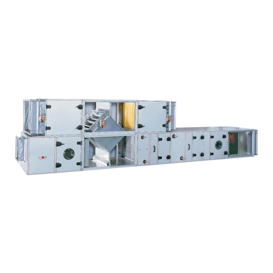
- Page 1 Installation and Maintenance Instructions KG / KGW Standard air-conditioning units Wolf GmbH · 84048 Mainburg · Postfach 1380 · Telefon 08751/74-0 · Telefax 08751/741600 Art.-Nr. 30 40 530 10/00 TV GB...
-
Page 2: Table Of Contents
Contents Contents ..................Page Warnings / Notes on safety ..............3 Standards .................... 4 Delivery to site / Transportation ............5 Notes on installation................ 6-12 Connection to electricity supply ............ 13-14 Initial operation ................15-17 Maintenance ................. 18-19 Protection against frost ..............19... -
Page 3: Warnings / Notes On Safety
Warnings / Notes on safety General These Installation and Maintenance Instructions apply only to WOLF KG and KGW Standard air-conditioning units. The persons charged with the installation, initial operation or maintenance of the equipment must read these instructions before commencing work. -
Page 4: Standards
Standards Standards The standards and regulations applicable to the KG 15-250 Standard series and the KG/KGW 630-1000 series air-conditioning units are as follows: - EC Directive 89/392/EC with Addendum 93/44/EC (9th Ordinance, Equipment Safety Law) - E Directive 89/336/EC with Addendum 92/31/EC (Law concerning Electromagnetic Compatibility of Devices) - EC Directive 73/23/EC (Low Voltage Directive) (1st Ordinance, Equipment Safety Law) -
Page 5: Delivery To Site / Transportation
Make a note of all damage or suspected damage on the waybill and have this damage report countersigned by the delivering freight forwarder. Immediately report the situation to WOLF. The equipment must always be transported right way up, in other words in the... -
Page 6: Notes On Installation
Notes on installation Foundation Install the units and components on a surface which is smooth, level and of Caution adequate load-bearing strength. The base frames must be horizontal and the foundations must be smooth-topped KG 40-250: and horizontal. Make sure that the bottom of the frame is in full-face contact with the supporting surface: spot support is not permissible. - Page 7 Notes on installation Base frames are either secured to the unit or delivered separately (in advance). Base frames delivered in advance are in sections and must be assembled on site in accordance with the instructions enclosed with the shipment, then aligned and secured to the supporting surface.
- Page 8 Notes on installation Securing the sections Sections with angle-section frames (KG 40-250) are secured by means of M6 threaded fasteners and clip spacers. Sections with square-section tubular frames (KG/KGW 630-1000) require M12 bolts. The cubes have pre-drilled holes to accommodate the threaded fasteners. All the small items required for assembly are shipped along with the accessories packed inside a section with an inspection door (usually the fan section).
- Page 9 Notes on installation Configurations: Sections for stacked configurations are delivered to site separately and must be stacked or side-by-side secured together on site with the aid of the enclosed self-tapping screws (KG 40- 250) or enclosed accessories (KG/KGW 630-1000). The sections which make up the stacked or side-by-side configuration cannot be secured together until the various transportable units have been installed on site in their final positions.
- Page 10 Notes on installation KGW roof The weatherproofed KGW 630-1000 air-coinditioning units have a UV-resistant, weatherproof skinned roof. Fully assembled units are supplied complete with the roof pre-installed. Each section of a sectionalized unit has its own roof; the butt joints in the roof must be sealed on site once the sections are installed.
- Page 11 Notes on installation Fan section The fan shaft must always be horizontal. Caution Remember to remove the transportation locking devices of fans mounted on vibration damper springs. Locking When installing, bear in mind that the maximum permissible distance between the devices connecting flanges is 100 mm, in order to ensure that the sailcloth adapter has full freedom of movement.
- Page 12 Each condensate drain requires an siphon of its own. It is not permissible to connect two or more drains to a common siphon. Siphons are available from WOLF as accessories. In this case the height of the siphon is calculated ex-works.
-
Page 13: Connection To Electricity Supply
Connection to electricity supply Connection to electricity The air-conditioning unit must be wired by a trained, qualified electrician in supply accordance with the applicable regulations (VDE, local power utility, etc.). If the intake fan or discharge fan is switched off or fails, all control valves must close automatically and the hot-water/cold-water and washer pumps must shut down. - Page 14 Connecting to electricity supply Wiring for single-speed drive Wiring for three-speed drive Motors up to 2.2 kW usually have direct startup, (2 separate windings, 1 is a Dahlander winding) whereas a star-delta circuit is usual as of 3 kW. For fan drives with speeds of 500/1000/1500 rpm or 8/6/4-pole;...
-
Page 15: Initial Operation
Initial operation Wait until the fan or fans run down to a complete standstill before you open the inspection door. Check that safety devices and monitoring devices are correctly installed and fully functional. - Do not start the unit until all ducts have been connected and the inspection doors Fan section closed. - Page 16 Initial operation Heater Check the entire piping system for leaks before initial startup. (Warm water/hot water/steam) - Bleed the heat exchanger and the piping system. - Make sure that condensation drains correctly from the steam register, if fitted, to avoid the danger of steam shocks damaging the register. - Do not switch on the hot-water pump or open the water/steam valve unless the fan is running, to avoid overheating due to insufficient removal of heat.
-
Page 17: Initial Operation
Initial operation Chiller Before filling the chiller system with refrigerant, adopt suitable measures to ensure (direct evaporator) that no traces of moisture are left in the piping system (e.g. by evacuation or by flushing with dry nitrogen). Check the air-discharge temperature: min. air-discharge temperature +2 °C, at air- discharge and refrigerant temperatures lower than + 2 °C there is a danger of the heat exchanger icing. -
Page 18: Maintenance
Maintenance Before starting maintenance work, always switch off the main switch and repair switch(es) and lock them in the OFF position. Wait until the fan runs down to a standstill before opening the inspection door. Lubricatable fan bearings must be lubricated with lithium-saponified grease every 2500 operating hours. -
Page 19: Protection Against Frost
Maintenance / Frost protection Washer The washer and drip separator must be cleaned at regular intervals. The cleaning cycle depends on the operating mode, the condition of the air and the water quality. The tray has to be drained for maintenance and rinsed with clean water or with a high-pressure cleaner. - Page 20 Structural measures for explosion protection in fans (explosion-proof devices) We hereby declare that the electrical equipment for Wolf airconditioning units type KG, KGW and KG/WO including the special control cabinets for said products and the control accessories: room thermostats, room-thermostat timers, remote-control units, actuating motors, valves, valve drives, channel sensors,...