
Related Manuals for Sony HVR-M15E


Summary of Contents for Sony HVR-M15E
- Page 1 Digital HD Videocassette Recorder Operating Instructions HVR-M15U/M15N/M15E/M15P 2006 Sony Corporation 2-678-753-11(1)
- Page 2 The model number and the serial number are located at the name plate on the left of the unit. Record the serial number in the space provided below. Refer to these numbers whenever you call upon your Sony dealer regarding this product. Model No. HVR- Serial No. ______________________ Model No.
- Page 3 Never use the plug without the fuse cover. If you should lose the fuse cover, please contact your nearest Sony service station. Disposal of Waste Electrical and Electronic...
-
Page 4: Table Of Contents
Table of Contents Table of Contents Chapter1 Overview Chapter2 Playback and Recording Chapter3 Dubbing/Editing Table of Contents Features ... 6 Location and Function of Parts ... 8 Front Panel ... 8 Rear Panel ... 13 Supplied Remote Commander ... 16 Displaying Various Data ... - Page 5 Chapter4 Adjusting and Setting Through Menus Chapter5 Maintenance Appendix Operating the Menus ... 44 Menu Organization ... 45 Menu Contents ... 46 Troubleshooting ... 56 Warning indicators and messages ... 62 Notes on Use ... 64 Notes on the Videocassette Recorder ... 64 Cleaning of the Video Heads ...
-
Page 6: Features
Features The HVR-M15U/M15N/M15E/M15P is a digital HD videocassette recorder supporting HDV format and DVCAM/DV format. The unit produces stable, superior picture quality by digital processing and separating image signals into color difference signals and a luminance signal (component video). The unit provides i.LINK ( HDV/DV) jack, COMPONENT OUT jacks, S VIDEO IN/OUT jacks, composite IN/ OUT jacks, and AUDIO IN/OUT jacks. - Page 7 , and are trademarks of Sony Corporation. is a trademark of Sony Corporation and Victor Company of Japan Ltd. All other product names mentioned here may be the trademarks or registered trademarks of their respective companies. “™” and “®” are not mentioned in each case in this manual.
-
Page 8: Location And Function Of Parts
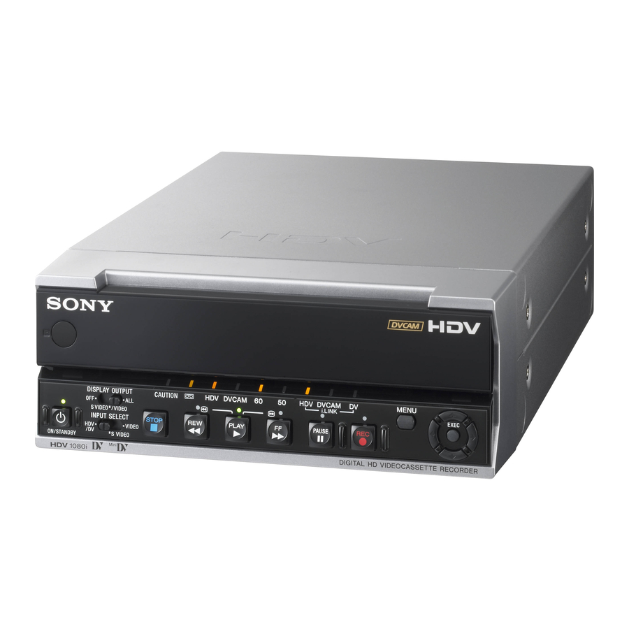
Location and Function of Parts Front Panel 2 Indicator section (see page 11) 1 Remote sensor 2 DISPLAY OUTPUT switch 3 ON/STANDBY switch and lamp 4 INPUT SELECT switch 1 Remote sensor 2 DISPLAY OUTPUT switch Selects the destination for the text data to be superimposed via output jacks. - Page 9 6 J/j/K/k button Use these buttons in menu settings and other settings. 7 EXEC (execute) button Use this button in menu settings. 8 MENU button Press this button to display the menu on screen. Chapter 1 Overview...
- Page 10 Location and Function of Parts 1 Tape transport control section 6 REW (rewind) button 7 STOP button 1 Tape transport indicators 2 REC (record) button When you press and hold this button then press PLAY button, the each indicator lights and recording starts. If you press this button while the tape is stopped, you can check EE picture and audio signals for a moment.
- Page 11 5 PLAY button When you press this button, the indicator lights and playback begins. If you press this button while holding down REW button during stop, the tape is rewound to its beginning and starts playing automatically (during rewind, REW indicator lights and PLAY indicator blinks).
- Page 12 Location and Function of Parts 3 HDV indicator Lights when the unit is in the following operating status. • When a tape recorded in HDV format is being played back. • When HDV signals are input through the i.LINK interface. •...
-
Page 13: Rear Panel
Rear Panel 1 S VIDEO jacks 2 VIDEO jacks 3 AUDIO jacks 4 CONTROL S jack 5 RESET button 1 S VIDEO jacks To connect a device equipped with an S VIDEO jack, use S VIDEO jacks on the unit. If you use S VIDEO jacks, you can input/output high- quality video with less signals deterioration in quality than the one connected to the standard VIDEO jack. - Page 14 Location and Function of Parts 6 COMPONENT OUT jacks Use to output component signals. To connect a device equipped with the component video input connectors, use COMPONENT OUT jacks on the unit. If you use COMPONENT OUT jacks, you can output high-quality video with even less signal deterioration in quality compared with S VIDEO jack.
- Page 15 • When connecting a device that has a 6-pin i.LINK jack to the unit, first, connect the plug of the cable to the 6-pin i.LINK jack. • The video signal which is input from HDV/DV jack will output directly to COMPONENT OUT jacks, S VIDEO jack, and VIDEO jack with the jitter of i.LINK signal.
-
Page 16: Supplied Remote Commander
Location and Function of Parts Supplied Remote Commander 1 EJECT button 2 SEARCH SELECT buttons 3 Buttons for playing at various speeds 4 PAUSE button 5 REW button 6 PLAY button 1 EJECT button Note The unit does not open and close Cassette Lid 5 (page 8) automatically. - Page 17 [WIRELESS] to enable Remote Commander to control the unit. • In addition to Remote Commander supplied with the unit, the unit accepts signals from any Sony Remote Commander whose command mode is set to VTR4. To disable the control from Remote Commander, set [COMMANDER] in [OTHERS] menu to [CONTROL S].
-
Page 18: Displaying Various Data
Displaying Various Data The unit can display various superimposed text data on an external monitor connected to the unit. In this operation manual, the menu screen etc. is displayed in English. You can change the desired language with the screen language setting. For details, see page 53. - Page 19 qs Audio level meters For details of the audio level meter display, see “AUDIO MIX” in “AUDIO SET” menu on page 50. qd Date/time and camera data indicator When you press DATA CODE button of Remote Commander or when you select [DATE] or [CAMERA DATA] of [DATA CODE] in [DISPLAY SET] menu, you can switch the display between recordings date/time and camera data.
-
Page 20: Notes On Power Supply And Video Cassettes
Notes on Power Supply and Video Cassettes Usable cassettes We recommend you to use a DigitalMaster of standard HDV/DVCAM/DV cassette (such as PHDV-276DM), or mini HDV/DVCAM/DV cassette (PHDVM- 63DM) for recording in HDV/DV format. We recommend you to use a standard DVCAM cassette, Mini-DVCAM cassette, or DigitalMaster described above for recording in DVCAM format. -
Page 21: Preparing The Power Supply
Preparing the Power Supply Connect the power cord (supplied) to the AC adaptor (supplied) and the DC plug of the AC adaptor to DC IN jack on the unit. Next, connect the power plug to an AC outlet. When you disconnect the power cord, be sure to unplug the power cord from the AC outlet first. -
Page 22: Notes On Playback/Recording
Notes on Power Supply and Video Cassettes Notes •When inserting a cassette, hold the back edge of the cassette in the center and push it until the cassette is inserted deep into the unit. If you hold the ends, the cassette may not be loaded properly. -
Page 23: Installing The Unit Vertically
If a tape has both a portion recorded in HDV/DVCAM format and one recorded in DV format (SP mode), the following limitations are applied when you play back the tape with the unit: • The image may be distorted and noise may occur at the point where the recording format changes on the tape. -
Page 24: Playback
Playback This section describes the connections and settings for the playback and functions such as playback at various speeds and searching for a specific scene on a recorded tape. Connections for Playback Connecting the unit to a monitor without an i.LINK jack You can connect the unit to video monitor without an i.LINK jack. - Page 25 Notes • To playback the picture recorded in HDV format when you connect the monitor using a component video cable, set [COMPONENT] of [VIDEO OUT] in [IN/OUT REC] menu according to your monitor (page 47). When the picture recorded in DVCAM/ DV format is played back, only a picture with a quality equivalent with DVCAM/DV format of 480i (NTSC) or 576i (PAL) is output via COMPONENT...
- Page 26 Playback • If you connect the input connectors of the unit to the output connectors of a monitor, a humming noise may be generated or the image may be distorted. If these phenomena occur, use INPUT SELECT switch to select a signal that is not being input or disconnect the cables.
-
Page 27: Settings For Playback
Settings for Playback Preparation on the unit Notes • Text information is superimposed to VIDEO OUT jack, S VIDEO OUT jack, and COMPONENT OUT jacks. To record video signals without text data, set DISPLAY OUTPUT switch to OFF (page 8). For details on text data, see “Displaying Various Data”... -
Page 28: Playback Functions
Displaying information (data codes) recorded on a tape If you record on a tape using a Sony digital HD video camera recorder or digital camcorder, the recording information (data codes) will be recorded on the tape. The data codes consist of recording date/time and camera data (the shutter speed, SteadyShot, iris, white balance, program AE mode, gain, date and time). - Page 29 C button; in the backward direction, press c button. Notes • When the command mode of a Sony device/remote commander is set to VTR4: – if you press ×1/3 button on the supplied Remote...
- Page 30 For duplicating with the DSR-25/45/50, see page 20. • Searching may not be done correctly if the tapes were not recorded on Sony-brand digital video equipment. SEARCH Search signal If D is recorded over the beginning of B...
- Page 31 Auto Repeat The unit can repeat the playback of all or a part of the tape. Set [AUTO REPEAT] in [VTR SET] menu to [ON]. Press REW button (if the tape is already rewound, press PLAY button). The unit rewinds the tape to its beginning, and starts playback automatically.
-
Page 32: Using The Unit As A Videocassette Recorder
Using the Unit as a Videocassette Recorder This section describes the connections, settings and operations necessary to perform recording on the unit. The same settings and operations apply whether you are using the unit for dubbing. Notes • For connection of the editing devices, refer to the instruction manual of the editing controller and that of the editing software you use. - Page 33 Notes • If you connect the output connectors of the unit to the input connectors of the player, a humming noise may be generated or the image may be distorted. If these phenomena occur, set INPUT SELECT switch to a position where a signal is not currently being input, or disconnect the cables.
-
Page 34: Settings For Recording
Using the Unit as a Videocassette Recorder • The unit cannot record MPEG2 signals except HDV1080i signals. • When you record HDV signals input from HDV/DV jack, the connection between the recorded picture pauses for a second. Settings for Recording Preparation on the recorder (the unit) Notes •... - Page 35 If INPUT SELECT switch is set to S VIDEO or VIDEO, select the audio mode. (With a HDV/DV connection, skip step 6, 7, and 8.) When you select S VIDEO or VIDEO with INPUT SELECT switch, set AUDIO mode by setting [AUDIO MODE] in [AUDIO SET] menu (page 50).
-
Page 36: Recording Procedures
Using the Unit as a Videocassette Recorder Recording Procedures This section describes the procedures used to record signals sent from another VCR to the unit. For details on the operation when the unit is connected to a computer via HDV/DV jack, refer to “Editing (Connecting with a Computer)”... -
Page 37: Dubbing To Another Equipment
Dubbing to another equipment The section describes the connections and settings necessary to perform dubbing on other equipment, using the unit as a video player. Connections for Dubbing To digital video equipment with an i.LINK jack Connect the unit to the recorder as shown right using an i.LINK cable. - Page 38 Dubbing to another equipment To dub a tape recorded in HDV format using duplicate function on such as the DSR-25/45/50, select [DVCAM] in [HDV t DV CONV] of [i.LINK SET] in [IN/OUT REC] menu. There are some limitations to down convert a tape recorded in HDV format to DVCAM format.
- Page 39 To video equipment without an i.LINK jack When connecting the unit to a recorder without an i.LINK jack, connect the two devices as shown below. Set [COMPONENT] and [DOWN CONVERT] setting of [VIDEO OUT] in [IN/OUT REC] menu (page 47) corresponded to the signals you wish to output.
-
Page 40: Dubbing Procedures
Dubbing to another equipment Dubbing procedures Prepare the unit. Refer to “Settings for Recording” on page 34. Prepare the recorder. If the recorder has an input selector switch, select an input. For details, refer to your recorder’s instruction manual. Start playback on the unit and start recording on the recorder. -
Page 41: Editing (Connecting With A Computer)
Editing (Connecting with a Computer) You can set up an editing system by connecting the unit to a computer (editing machine) using HDV/DV jack on the unit. • For details about the connecting method to the editing machine, refer to the supplied instruction manual of your editing unit. -
Page 42: Preparations
Editing (Connecting with a Computer) Preparations Transferring the picture data from the unit to a computer (editing machine) • To transfer the picture data recorded on a tape to an editing machine in HDV, set [HDV/DV SEL] in [IN/ OUT REC] menu to [HDV] (page 46), then set [HDVtDV CONV] of [i.LINK SET] in [IN/OUT REC] menu to [OFF] (page 47). - Page 43 Transferring the picture data on a computer (editing machine) to the unit • To transfer the picture data recorded on a tape to an editing machine in HDV, set [HDV/DV SEL] in [IN/ OUT REC] menu to [HDV], then set [HDV t DV CONV] of [i.LINK SET] in [IN/OUT REC] menu to [OFF] (pages 46, 47).
-
Page 44: Operating The Menus
Operating the Menus The unit allows you to set various parameters in the menus. Before you start using the unit, set the internal clock in [CLOCK SET] in [OTHERS] menu. Except for clock setting, you can use all other factory-set default parameters but change them as needed. -
Page 45: Menu Organization
Menu Organization The menu of the unit consists of the following menus and submenus. IN/OUT REC HDV/DV SEL (page 46) REC MODE (page 46) VIDEO OUT (page 47) i.LINK SET (page 47) COLOR BAR (page 48) BARS TYPE (page 48) DV BARS (page 48) EE/PB SEL (page 48) 480i LEVEL (page 48) -
Page 46: Menu Contents
Operating the Menus Menu Contents Initial settings are indicated with rectangles. IN/OUT REC menu Icon/Menu Submenu Setting HDV/DV SEL Normally, set this menu to [AUTO]. Select this menu when you want to limit the output IN/OUT REC (pages 25, format during tape playback or limit the signals to be input or output from HDV/DV jack. 33, 37, 41) This setting will affect analog outputs. - Page 47 Icon/Menu Submenu Setting IN/OUT REC VIDEO OUT Selects the mode of video output jacks. COMPONENT Selects the output format from COMPONENT OUT jacks. Selects from [480i], [480p/480i] or [1080i/480i] when [60i/50i SEL] in [OTHERS] menu is set to 60i. Selects from [576i], [576p/576i] or [1080i/576i] when [60i/50i SEL] in [OTHERS] menu is set to 50i.
- Page 48 Operating the Menus Icon/Menu Submenu Setting IN/OUT REC COLOR BAR Selects whether to display color bars or not. Also, you may select color bars with or without tone signals (1 kHz full bit –20 dB at 60i, 1 kHz full bit –18 dB at 50i). OFF : ON : ON [TONE] :...
- Page 49 DISPLAY SET menu Icon/Menu Submenu Setting DISPLAY SET DATA CODE Selects whether or not to display the data codes on the analog video output. (page 28) OFF : DATE : CAMERA DATA : Displays the camera data. LETTER SIZE Selects the letter size of the menu at the cursor. NORMAL : 2×...
- Page 50 Operating the Menus AUDIO SET menu Icon/Menu Submenu Setting AUDIO MODE Selects the audio mode. AUDIO SET (page 35) FS32K : FS48K : Notes • When signals are input from HDV/DV jack, the audio mode of the signals to be recorded is the same as that of the input signals.
- Page 51 Icon/Menu Submenu Setting AUDIO LOCK UNLOCK MODE : Records the sampling clocks of audio and video independently. This AUDIO SET LOCK MODE : Synchronizes the sampling clocks of the audio and video for recording. Notes • You can set this menu when recording in DV format (SP mode) only. •...
- Page 52 Operating the Menus Icon/Menu Submenu Setting VTR SET STILL TIME Selects the time to switch to the tape protection mode from the still mode. 30 sec : 1 min : 2 min : 3 min : Notes • If the unit is left in playback pause mode for a long time, the tape or the video heads may be damaged or the video heads may become clogged.
- Page 53 CONTROL S : Enables the control of the remote control unit DSRM-10 (not supplied) Notes • The unit accepts signals from any Sony Remote Commander whose command mode is set to VTR4, not only the supplied one. To disable the control from any Remote Commander, set this item to [CONTROL S].
- Page 54 Operating the Menus Icon/Menu Submenu Setting OTHERS PB YNR Selects the noise reduction level for the luminance signals when a tape is played. OFF : LOW : HIGH : Notes • When you use noise reduction, there may be an afterimage depending on the condition of the picture.
- Page 55 Icon/Menu Submenu Setting OTHERS 60i/50i SEL Switches to the 1080/60i (NTSC) or the 1080/50i (PAL). (page 34) 1 Press J/j buttons to select [YES], then press EXEC button. 2 Press J/j buttons to select [YES] again, then press EXEC button. INITIALIZE Resets the menu to factory settings except CLOCK SET.
-
Page 56: Troubleshooting
Adjust the menu again. To prevent this incident recurring, do not pull out the plug while adjusting the menu. • [COMMANDER] in [OTHERS] menu is set to [WIRELESS] and a Sony Remote Commander whose command mode is set to VTR4 is operated near the unit. -
Page 57: Power Sources
Power sources Symptom The power cannot be turned on. The unit does not operate even if the power has been turned on. The unit does not operate properly when the AC adaptor is used. Cassette tapes Symptom The cassette cannot be inserted. It takes time to eject the cassette. - Page 58 Troubleshooting Output/Playback Symptom Cannot playback. Cannot playback in reverse at various speeds. Horizontal lines are displayed on an image. An image has block noise. An image is blurred or not displayed. No picture is output from HDV/DV jack. The audio breaks up. Cannot perform a date search and index search.
- Page 59 Symptom Even though [HDV/DV IN TC] in [TC/UB SET] menu is set to [EXTERNAL], the time code of the input i.LINK signal is not recorded. After playing at 1/10 of normal speed in forward or reverse for more than 1 minute, normal playback forward starts.
- Page 60 Troubleshooting Symptom The unit does not function as part of a digital non-linear editing system. Although the i.LINK cable is connected, the image from an external equipment is not displayed. No image is displayed even though the video cable is connected correctly. The image loses color or is distorted when you play back the tape on a television set or monitor connected to the unit.
- Page 61 Recording Symptom No picture is output via HDV/DV jack. About the audio level setting: • You do not know how to adjust the input level. • The recorded level is too low. • The recorded sound is distorted. No sound or undesired sound is output from AUDIO jacks in OUTPUT.
-
Page 62: Warning Indicators And Messages
Chapter 5 Maintenance Cause/Corrective Action If an error still recurs after you retry the corrective actions several times, contact Sony Customer Service or your place of purchase. C:21:ss t Condensation has occurred. Remove the cassette and insert it again after approximately 1 hour (page 66) . -
Page 63: Alarm Messages
Alarm Messages The following alarm messages appear with the alarm indicators. Take appropriate action according to the displayed message. Item Message % Z Moisture condensation. Eject the cassette. Moisture condensation % Moisture condensation. Turn off for 1H. Q Insert a cassette. Cassette/Tape Z Reinsert the cassette. -
Page 64: Notes On Use
Notes on Use Notes on the Videocassette Recorder Do not use the unit in a place subject to direct sunlight or heat sources If you do, its cabinet, mechanical parts, etc., may be damaged. Do not place the unit in humid places Do not place the unit in places where they may be exposed to water-splash or to humidity. -
Page 65: Notes On The Video Cassettes
In that case, you have to replace the video heads with new ones. Please consult your Sony dealer. Notes on the Video Cassettes Note that using a tape such as those below can damage the unit. -
Page 66: About Moisture Condensation
These counts can be displayed on the menu. Use them as guidelines for scheduling maintenance. In general, consult your Sony dealer about necessary periodic maintenance checks. The digital hours meter has the following four display modes and you can check them in [HOURS METER] of [OTHERS] menu (page 54). -
Page 67: About The Built-In Rechargeable Battery
Notes on Use • TAPE RUN mode The cumulative total hours of tape running time is displayed in 10-hour increments. • THREADING mode The cumulative number of tape unthreading operations is displayed in 10-operation increments. About the Built-in Rechargeable Battery The unit is provided with a rechargeable battery that retains the date/time and various settings regardless of power-on and power-off. -
Page 68: Compatibility Of Hdv, Dvcam, And Dv Formats
Compatibility of HDV, DVCAM, and DV Formats HDV format is an HD VCR format based on DV format of the globally widespread general consumer digital VCR system. This format has the newly defined data recording specifications for HD signals compressed by MPEG2. It applies the same cassette, tape speed, and track pitch as DV format. - Page 69 Playback compatibility The compatibility between playback tape format and player is summarized in the table below. Player Playback DV format model tape format Playback is possible. (Some equipment cannot play a tape recorded in LP mode.) DVCAM Playback may be possible on some models.
- Page 70 Compatibility of HDV, DVCAM, and DV Formats Dubbing with S VIDEO or VIDEO jacks When you use the unit as a recorder to perform dubbing between the unit and another equipment connected, the format to be used for recording is set in accordance with [ For details, see the following table.
- Page 71 Dubbing with HDV/DV jack When you perform dubbing between the unit and digital video equipment connected with the i.LINK cable using the unit as a player, HDV/DV jack output format is determined in accordance with the playback tape format and menu setting of the unit.
- Page 72 Compatibility of HDV, DVCAM, and DV Formats Recording tape when the unit is used as a recorder Menu item i.LINK input format HDV/DV SEL AUTO DVCAM AUTO AUTO 1) When the unit is used as a recorder, the recording format is determined by [ menu if the input signal format is DVCAM or DV.
-
Page 73: About I.link
• i.LINK is an easy-to-remember term for the IEEE 1394 proposed by Sony, and is a trademark approved by many corporations in Japan and overseas. • IEEE 1394 is an international standard standardized by the Institute of Electrical and Electronics Engineers. -
Page 74: Specifications
Specifications System Video/Audio recording/playing Head System Rotating dual-head helical scan Audio recording format (HDV) MPEG-1 Audio Layer2 16-bit 48 kHz (stereo) Transfer rate 384 kbps Audio recording format (DVCAM (DV)) 12-bit Fs32K (Channel 1/2, Channel 3/4) 16-bit Fs48K (Channel 1/2) Video signal 1080/60i, NTSC color, EIA standard system... - Page 75 COMPONENT OUT jacks Pin jack Output at 480i NTSC With [BETACAM] selected in [IN/OUT REC] menu Y: 1.0 Vp-p (with 0.286 Vp-p sync negative, output impedance 75 Ω (ohms), unbalanced) Pb/Cb/B-Y, Pr/Cr/R-Y: 0.7 Vp-p (output impedance 75 Ω (ohms), unbalanced) (75% color bars with 7.5 IRE setup) With [SMPTE] selected in [IN/OUT REC] menu...
- Page 76 Specifications Supplied accessories Remote Commander (1) AC adaptor (1) Power cord (1) Rack (1) Size AA batteries (2) Cleaning cassette (1) Operating instructions (1) AC adaptor Power requirements 100 – 240 V AC, 50/60 Hz Current consumption 0.35 – 0.18 A Power consumption 18 W Output voltage...
-
Page 77: Index
Index Alarm message ... 63 Audio mode ... 18 Camera data ... 28 Cassette ... 20 Cassette memory ... 20 Cleaning cassette ... 65 Clock ... 54 Data code ... 28 Data display screen ... 18 Date search ... 30 Drop Frame ... -
Page 78: Submenu Index
Submenu Index Numerics 480i LEVEL ... 48 60i/50i SEL ... 55 AC ON MODE ... 54 AUDIO AGC ... 50 AUDIO LOCK ... 51 AUDIO MIX ... 50 AUDIO MODE ... 50 AUDIO REC LV ... 50 AUTO INDEX ... 51 AUTO REPEAT ... - Page 80 Printed on 100% recycled paper using VOC (Volatile Organic Compound)- free vegetable oil based ink. Printed in Japan...