
Related Manuals for Danby DPAC120011H


Summary of Contents for Danby DPAC120011H
- Page 1 • PORTABLE AIR CONDITIONER • CLIMATISEUR PORTATIF Owner’s Use and Care Guide Guide d’utilisation et soins de Propriètaire Model • Modèle DPAC120011H V2.03.11.DM...
-
Page 2: Table Of Contents
• Consignes de Sécurité Important ......21-22 • l'identification des pièces ........22-24 • Consignes d’utilisation .........25-28 • Fonctionnement de la télécommande sans fil ..28-29 • Installation ............30-33 • Soins et entretien ..........34-35 • Dépannage ............36 • Garantie ...............37 Model • Modèle DPAC120011H... -
Page 3: Welcome
Welcome Thank you for choosing a Danby appliance to provide you and your family with all of the “Home Comfort” requirements of your home, cottage, or office. This Owner’s Use and Care Guide will provide you with valuable information necessary for the proper care and maintenance of your new appliance. -
Page 4: Important Safety Information
Important Safety Information READ AND FOLLOW ALL SAFETY INSTRUCTIONS To prevent injury to the user or other people and property damage, the following instructions must be followed. Incorrect operation due to ignoring these instructions may cause harm or damage. SAFETY ALWAYS DO THIS PRECAUTIONS Your air conditioner should be used in such a way that it is protected... -
Page 5: Identifying Parts
Important Safety Information READ AND FOLLOW ALL SAFETY INSTRUCTIONS To prevent injury to the user or other people and property damage, the following instructions must be followed. Incorrect operation due to ignoring these instructions may cause harm or damage. ENERGY SAVING TIPS •... - Page 6 Identifying Parts ACCESSORIES PARTS PART NAME QUANTITY Exhaust hose and Adaptor Window slider kit and bolt. 1 Set Band (For bundling the 1 pc power cord) * 3 pc Foam Seal Remote Controller and 2-AAA 1 set Batteries included Check all the accessories are included in the package and please refer to the installation instructions for their usage.
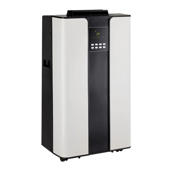
- Page 7 Identifying Parts FRONT 1. Operation Panel 2. Horizontal Louver Blade (Lift it up during operation) 3. Air intake (air filter inside) 4. Carrying Handle (both sides) NOTE: The illustrations are for explanation purposes only. The actual shape of the machine you purchased may be slightly different.
-
Page 8: Operating Instructions
Operating Instructions CONTROL PANEL Before you begin, thoroughly familiarize yourself with the control panel and remote controller and all its functions, then follow the symbol for the functions you desire. The unit can be controlled by the unit control panel alone or with the remote controller. - Page 9 Operating Instructions INDICATOR LIGHTS Timer on indicator Sleep operationn ON THE DISPLAY Timer off indicator Turbo display Turbo Auto operation indicator WINDOW auto Cooling operation indicator Dry operation indicator Fan operation indicator Heating operation indicator Fan Speed Indicator Low --------- Medium---- High -------- Display Window...
- Page 10 Operating Instructions BUTTON FUNCTIONS UP/ DOWN BUTTONS • Used to adjust (increasing/decreasing) temperature settings(1°C/2°F ON CONTROL PANEL increments) in a range of 17°C(62°F) to 30°C(88°F). NOTE: The control is capable of displaying temperature in degrees Fahrenheit or degrees Celsius. To convert from one to the other, press and hold the buttons at the same time, for 3 seconds.
-
Page 11: Operation Of Wireless Remote Control
Operating Instructions OPERATING INSTRUCTIONS COOL feature FAN feature • Press the "MODE" button until the " " indicator light • Press the "MODE" button until the " " indicator light comes on. comes on. • Press the buttons to select your desired •... - Page 12 Operation of wireless remote control PARTIDENTIFICATION: Fan Speed Selection button: Pressing alternates between available fan speeds (some operations only). Power On/Off button: Pressing activates or deactivates operation of the machine. NOTE: To disconnect power completely, the power cord must be removed after deactivating the machine. during the sleeping time.
-
Page 13: Installation Instructions
Installation Instructions • The air conditioner should be placed on a firm foundation to minimize LOCATION noise and vibration. For safe and secure positioning, place the unit on a smooth, level floor strong enough to support the unit. • The unit has casters to aid placement, but it should only be rolled on smooth, flat surfaces. - Page 14 Installation Instructions INSTALLATION IN A 1. Cut the foam seal (adhesive type) to the proper length and attach it to the window stool. Fig.8 DOUBLE - HUNG SASH 2. Attach the window slider kit to the window stool. Adjust the length of WINDOW the window slider kit according to the width of window, shorten the adjustable window kit if the width of window is less than 26.5 inches.
- Page 15 Installation Instructions INSTALLATION IN A 1. Cut the foam seal (adhesive type) to the proper length and attach it to the window frame. See Fig.12. SLIDING SASH 2. Attach the window slider kit to the window stool. Adjust the length of WINDOW the window slider kit according to the height of window, shorten the adjustable window kit if the height of window is less than 26.5 inches.
-
Page 16: Installation Instructions
Installation Instructions EXHAUST HOSE The exhaust hose and adaptor must be installed or removed in accordance with the usage mode. INSTALLATION: COOL Install FAN,DEHUMIDIIFY or HEAT mode Remove 1. Install the window Exhaust adaptor (flat mouth) onto the exhaust hose as shown in Fig.16. Refer to the previous pages for window kit installation. -
Page 17: Care And Maintenance
Care and Maintenance WATER DRAINAGE During Dehumidifying modes, remove the drain plug A from the back of the unit (Fig.21), install the drain connector (5/8” universal female connecter) with 3/4” hose (locally purchased). when the level of the bottom tray reaches a predetermined level, the unit beeps 8 times, the digital display area shows “P1”... -
Page 18: Care And Maintenance
Care and Maintenance CLEANING 1) Be sure to unplug the unit from the power before cleaning or servicing. 2) Do not use gasoline, thinner or other chemicals to clean the unit. 3) Do not wash the unit directly under a tap or using a hose. It may cause electrical damage or danger. -
Page 19: Troubleshooting
Occasionally a problem may arise that is minor in nature, and a service call may not be neccessary. Use this troubleshooting guide for a possible solution. If the unit continues to operate improperly, call an authorized service depot or Danby’s Toll Free Number 1-800-263-2629 for assistance. SOLUTION... -
Page 20: Warranty
Nothing within this warranty shall imply that Danby will be responsible or liable for any spoilage or damage to food or other contents of this appliance, whether due to any defect of the appliance, or its use, whether proper or improper. -
Page 21: Bienvenue
Bienvenue Merci d’avoir choisi un appareil Danby qui vous fournira ainsi qu’à votre famille, le confort au foyer, à la maison, au chalet ou au bureau. Ce manuel d’utilisation vous offre des renseignements pratiques pour le soin et l’entretien de votre nouvel appareil. -
Page 22: Consignes De Sécurité Important
Consignes de sécurité important LISEZ TOUTE L'INFORMATION DE SÉCURITÉ AVANT UTILISATION POUR VOTRE SÉCURITÉ : Lisez ces instructions attentivement avant d’utiliser l’appareil et conservez-les afin de pouvoir vous y référer ultérieurement. PRÉCAUTIONS DE SUIVEZ TOUJOURS CES CONSIGNES: SÉCURITÉ L'appareil doit être utilisé dans un endroit à l'abri de l'humidité, comme la condensation, les éclaboussures d'eau, etc. -
Page 23: L'identification Des Pièces
Consignes de sécurité important LISEZ TOUTE L'INFORMATION DE SÉCURITÉ AVANT UTILISATION POUR VOTRE SÉCURITÉ : Lisez ces instructions attentivement avant d’utiliser l’appareil et conservez-les afin de pouvoir vous y référer ultérieurement. ÉCONOMISEZ • Utilisez l'appareil dans des pièces des dimensions recommandées. •... - Page 24 l'identification des pièces ACCESSOIRES PIÈCES QUANTITÉ NOM DES PIÈCES Tuyau d’évacuation et adaptateur Trousse de glissière pour 1 ensemble fenêtre et boulon. Bande (pour attacher le 1 pièce cordon d’alimentation) * Joint d’étanchéité en 3 pièces mousse Télécommande et pile (2 piles AAA incluses) 1 ensemble Assurez-vous que tous les accessoires sont inclus dans l’emballage et consultez la notice...
- Page 25 l'identification des pièces AVANT 1. Panneau de commande 2. Lame du louvre horizontal (soulevez-la pendant le fonctionnement) 3. Entrée d’air (filtre à air à l’intérieur) 4. Poignée de transport (sur les deux côtés) REMARQUE : Les illustrations servent à des fins d’explication seulement.
-
Page 26: Consignes D'utilisation
Consignes d’utilisation PANNEAU DE COMMANDE Avant de commencer, familiarisez-vous avec le panneau de commande et la télécommande et toutes leurs fonctions, puis suivez le symbole correspondant à la fonction désirée. L’appareil peut être commandé par le panneau de commande seulement ou par la télécommande. Fig. 3 L'illustration suivante est pour l'explication seulement. - Page 27 Consignes d’utilisation INDICATEURS Indicateur de minuterie en marche Fonctionnement sommeil LUMINEUX SUR Indicateur de minuterie arrêtée Affichage turbo Turbo Indicateur de fonctionnement L’AFFICHEUR auto automatique Indicateur de refroidissement Indicateur de déshumidification Indicateur de fonctionnement du ventilateur Indicateur de chauffage Indicateur de la vitesse du ventilateur Basse ---------- Moyenne------- Élevée ---------...
- Page 28 Consignes d’utilisation FONCTIONS DES 2) Boutons Plus et Moins: • Utilisés pour régler (augmenter/diminuer) les réglages de température BOUTONS DU (intervalles de 1 °C/2 °F) sur une plage de 17 °C (62 °F) à 30 °C (88 °F). PANNEAU DE REMARQUE : La commande peut afficher la température en degrés Fahrenheit ou en degrés Celsius.
-
Page 29: Fonctionnement De La Télécommande Sans Fil
Consignes d’utilisation MODE D’EMPLOI Fonction REFROIDISSEMENT • Appuyez sur le bouton « MODE » jusqu’à ce que • En mode AUTO, vous ne pouvez pas sélectionner la l’indicateur lumineux « » s’allume. vitesse du ventilateur . • Appuyez sur les boutons pour Fonction VENTILATEUR sélectionner la température désirée de la pièce. - Page 30 Fonctionnement de la télécommande sans fil CARACTÉRISTIQUES Appuyez pour alterner entre les vitesses de fonctionnement du Bouton de vitesse du ventilateur: ventilateur (certaines fonctions seulement). Bouton d’alimentation de courant «En marche/Arrêt»: Appuyez sur ce bouton pour activer ou désactiver l’unité. Remarque : complètement Pour débrancher l’unité, le cordon d’alimentation de courantdoit être retiré...
-
Page 31: Installation
Ne coupez jamais la section de la trousse de glissière pour fenêtre ou se trouve le trou. Pour obtenir une vidéo d’installation, rendez-vous à l’adresse www.danby.com. Fig.5 Fig.6 Fenêtre... - Page 32 Installation INSTALLATION DANS 1. Coupez le joint d’étanchéité en mousse (adhésif) à la longueur appropriée et fixez-le au rebord de la fenêtre. fig. 8 UNE FENÊTRE À 2. Fixez la trousse de glissière pour fenêtre au rebord de la fenêtre. GUILLOTINE DOUBLE Ajustez la longueur de la trousse de glissière pour fenêtre en fonction de la largeur de la fenêtre;...
- Page 33 Installation INSTALLATION DANS 1. Coupez le joint d’étanchéité en mousse (adhésif) à la longueur appropriée et fixez-le au cadre de la fenêtre. Voir fig. 12. UNE FENÊTRE 2. Fixez la trousse de glissière pour fenêtre au rebord de la fenêtre. COULISSANTE Ajustez la longueur de la trousse de glissière pour fenêtre en fonction de la hauteur de la fenêtre;...
-
Page 34: Installation
Installation INSTALLATION DU Le tuyau d’évacuation et l’adaptateur doivent être installés ou enlevés, selon le mode d’utilisation. TUYAU D’ÉVACUATION : Installer Modes REFROIDISSEMENT ou Auto Mode VENTILATEUR, DÉSHUMIDIFICATION Enlever 1. Installez l’adaptateur d’évacuation pour fenêtre (embouchure plate) dans le tuyau d’évacuation, tel qu’illustré dans la fig. 16. Reportez- vous aux pages précédentes pour l’installation de la trousse pour fenêtre. -
Page 35: Soins Et Entretien
Soins et entretien DRAINAGE DE L’EAU En mode déshumidification, enlevez le bouchon de drainage A de l’arrière de l’appareil (fig. 21), installez le raccord de drain (raccord femelle universel 5/8) sur un tuyau de ? po (acheté localement). Lorsque le niveau du plateau inférieur atteint une valeur prédéterminée, l’appareil émet 8 bips, l’afficheur indique «... -
Page 36: Soins Et Entretien
Soins et entretien NETTOYAGE 1) Assurez-vous de débrancher l’appareil avant de procéder au nettoyage ou à l’entretien. 2) Ne pas utiliser d’essence, de solvants ou d’autres produits chimiques pour nettoyer l’appareil. 3) Ne lavez pas l’appareil directement sous le robinet ou au moyen d’un tuyau d’arrosage. -
Page 37: Dépannage
Il peut arriver qu’un problème mineur se produise qui ne nécessite pas d’appel de service. Consultez ce guide de dépannage pour trouver une solution possible. Si l’appareil continue de mal fonctionner, appelez un atelier de réparation autorisé ou le numéro sans frais de Danby, au 1-800-263-2629, pour obtenir de l’assistance. PROBLÈME... -
Page 38: Garantie
être acquittés par l'acheteur. Cette garantie indique en aucun temps la responsabilité de Danby de l’avarie ou dommage de la vin ou autre contenu, soit par les vices de l’appareil, ou soit parl’utilisation convenable ou inexacte. - Page 39 • Type de produit • Part Number • Numéro de modèle • Part Description • Numéro de pièce • Description de la pièce Tel: 1-800-26- (1-800-263-2629) Danby Products Limited, Guelph, Ontario, Canada N1H 6Z9 Danby Products Inc. Findlay, Ohio, U.S.A. 45840...