Table of Contents
Advertisement
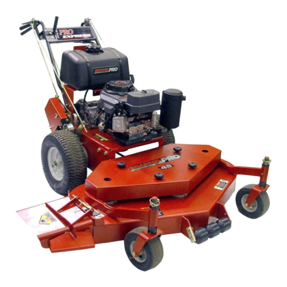
Safety Instructions and Operator's Manual for
MODEL DESIGNATION
MODEL TYPE
MODEL OPTION
S – Snapper Commercial Model
P – Pro Mid Size Model
E – Express Model
Thank you for buying a SNAPPER Product! Before operating your PRO GEAR WALK BEHIND, read this manual carefully
and pay particular attention to the "IMPORTANT SAFETY INSTRUCTIONS" on Pages 2 - 4. Remember that all power
equipment can be dangerous if used improperly. Also keep in mind that SAFETY requires careful use in accordance with
the operating instructions and common sense!
* Actual sustained equipment horsepower will likely be lower due to operating limitations and environmental factors.
COPYRIGHT © 2004
SNAPPER – A Division of Simplicity Manufacturing, Inc.
ALL RIGHTS RESERVED
WALK BEHIND MOWERS
MODEL NUMBER EXPLANATION
S
P
ENGINE HORSE POWER
13 – 13 Engine HP
15 – 15 Engine HP
PRO GEAR EXPRESS
E
13
1
CUTTING DECK WIDTH
361 – 36" Cutting Deck
481 – 48" Cutting Deck
MID-SIZE
SERIES 1
POWER UNIT
MODEL
SPE131KW
SPE151KW
MOWER UNIT
MODEL
SPE361
SPE481
KW
SERIES DESIGNATION
1 - Series Designation
KW – Kawasaki Engine
MANUAL No. 7-4324 (I.R. 8/04/04)
ENGINE TYPE
ENGINE HP
Advertisement
Table of Contents
Troubleshooting

Related Manuals for Snapper SPE131KW, SPE151KW, SPE361, SPE381


Summary of Contents for Snapper SPE131KW, SPE151KW, SPE361, SPE381
-
Page 1: Walk Behind Mowers
15 – 15 Engine HP Thank you for buying a SNAPPER Product! Before operating your PRO GEAR WALK BEHIND, read this manual carefully and pay particular attention to the “IMPORTANT SAFETY INSTRUCTIONS” on Pages 2 - 4. Remember that all power equipment can be dangerous if used improperly. -
Page 2: Important Safety Instructions
If you have any questions pertaining to your machine which your dealer cannot answer to your satisfaction, call or write the Customer Service Department at SNAPPER, McDonough, Georgia 30253. Phone: (1-800-935-2967). - Page 3 IMPORTANT SAFETY INSTRUCTIONS PREPARATION (Continued From Previous Page) 11. Protect yourself when mowing and wear appropriate clothing including safety glasses, long pants, ear protection, hardhat and substantial footwear with good traction. Long hair, loose clothing or jewelry may get tangled in moving parts. 12.
- Page 4 15. Have machine serviced SNAPPER dealer at least once a year and have the dealer install any new safety devices. DO NOT allow untrained personnel to service the machine. 16. Use only genuine SNAPPER replacement parts to assure that original standards are maintained.
-
Page 5: Table Of Contents
TABLE OF CONTENTS IMPORTANT SAFETY INSTRUCTIONS ...2-4 TABLE OF CONTENTS ... 5 SECTION 1 - FAMILIARIZATION ... 6 SECTION 2 - SAFETY MESSAGES & SYMBOLS...7-8 Controls... 9 SECTION 3 - OPERATING INSTRUCTIONS ...10-16 Before Operating... 10 Stopping Machine ... 10 Safety Interlock System Checks... -
Page 6: Section 1 - Familiarization
All SAFETY messages on the PRO GEAR WALK BEHIND MOWER and its attachments before operating. SNAPPER recommends MACHINE to an authorized SNAPPER dealer annually for inspection and addition of any new devices which might upgrade the safety of the mower. OPERATOR’S PRESENCE... -
Page 7: Section 2 - Safety Messages & Symbols
SECTION 2 - SAFETY MESSAGES AND SYMBOLS ENGINE ENGINE CHOKE BLADES ENGAGED“ON” “RUN” “STOP” FAST ENGINE SPEED KEYSWITCH BLADE SWITCH BLADES DISENGAGED“OFF” SLOW LEFT TRACTION LEVER RIGHT TRACTION LEVER SQUEEZE FOR LEFT TURN SQUEEZE FOR RIGHT TURN DANGER! ROTATING BLADES KEEP CHILDREN AND OTHERS OUT OF THE MOWING AREA DANGER! ROTATING BLADES... -
Page 8: Section 2 - Safety Messages & Symbols
SECTION 2 - SAFETY MESSAGES AND SYMBOLS IMPORTANT SAFETY AND OPERATING INSTRUCTIONS... -
Page 9: Controls
SECTION 2 - CONTROLS KEY SWITCH SHOWN IN “STOP” POSITION OPERATOR’S PRESENCE CONTROL (OPC) RIGHT HAND TRACTION LEVER To avoid sudden and unexpected turning, both Traction Levers must be moved the same way when stopping or starting machine motion. BLADE CLUTCH SWITCH TRACTION LOCK... -
Page 10: Section 3 - Operating Instructions
Perform the following interlock system checks periodically during the operating season. Contact your authorized Snapper dealer if you have questions. DO NOT operate machine if any safety interlock or safety device is not in place and functioning properly. -
Page 11: Pre-Start Checklist
SECTION 3 - OPERATING INSTRUCTIONS 3.4 PRE-START CHECK LIST Make the following checks and perform the services as required before each start-up: 1. If required, make cutting height adjustments. Refer to Section “CUTTING HEIGHT ADJUSTMENT”. 2. Check tires and add air as needed to bring pressure to 25 psi in front and 12-15 psi in rear tires. - Page 12 SECTION 3 - OPERATING INSTRUCTIONS 3.5 STARTING & OPERATING - (Continued from previous page) Move Engine Speed Control Lever to the CHOKE position. See Figure 3.5. Turn Key Switch to RUN position. MOVE ENGINE SPEED CONTROL TO CHOKE POSITION LEFT SIDE FIGURE 3.5 IMPORTANT: DO NOT jerk the engine recoil starter...
-
Page 13: Starting And Operating
SECTION 3 - OPERATING INSTRUCTIONS 3.5 STARTING & OPERATING (Continued from previous page) STOPPING MACHINE Simultaneously squeeze both Traction Levers firmly against the handle and hold. Pull both the right and left Traction Locks rearward with index fingers until both Traction Levers are locked in the Traction Locked position. -
Page 14: Traction Lock Operation
SECTION 3 - OPERATING INSTRUCTIONS WARNING Brakes require maintenance. Inspect for proper operation before operating machine. Refer to Section “ADJUSTMENTS, BRAKES”. 3.7 TRACTION LOCK OPERATION - 3.7.1 TO LOCK 1. Simultaneously squeeze both Traction Levers toward the handle, to stop movement of machine. 2. -
Page 15: Cutting Height Adjustment (Fixed Decks)
SECTION 3 - OPERATING INSTRUCTIONS 3.10 CUTTING HEIGHT ADJUSTMENT (Fixed Decks) Mower has three methods of adjusting cutting height: 1. Moving position of BLADE on cutter spindle shaft. 2. Moving position of CASTER WHEEL on support. 3. Moving position of MOWER DECK on power unit. WARNING DO NOT attempt any maintenance, adjustments or service with the engine running. -
Page 16: Adjusting Blade On Cutter Spindle
SECTION 3 - OPERATING INSTRUCTIONS 3.12 ADJUSTING BLADE ON CUTTER SPINDLE (Continued) CUTTER HOUSING PULLEY BLADE FIGURE 3.14 3.13 ADJUSTING FIXED DECK ATTACHMENT The mower deck has four different positions for attaching it to the power unit. The lowest setting provides a cutting height range of 1-1/2”... -
Page 17: Section 4 - Troubleshooting
SECTION 4 - TROUBLESHOOTING SYMPTOM PROBLEM Engine...Key OFF..Turn Key to Run. does not...Fuel Tank empty... Fill Fuel Tank. start...Fuel Shut-Off Closed..Open Fuel Shut-Off..Engine Throttle Control not at FAST (Rabbit) position... Put Engine Throttle Control to FAST ...Choke NOT closed. -
Page 18: Mower Troubleshooting
Obstructed..Engine overloaded... Run Engine at full Throttle and reduce TRANSMISSION TROUBLESHOOTING SYMPTOM PROBLEM Unit is ...Gearing is overly noisy - chatter, etc... Return to Authorized Snapper Dealer Noisy...Worn Gears..Worn Bearings - mainly input Shaft..Ball Bearing. Unit Jumps ...Teeth of Gears are worn beyond tolerances. -
Page 19: Section 5 - Adjustments
SECTION 5 - ADJUSTMENTS 5.1 STEERING/BRAKES If machine is not as responsive as desired when either Traction Lever is squeezed, one or both brakes should be adjusted as follows: 1. Operate mower on level terrain with Transmission Shift Lever in No. 1 position. brake requires adjustment. -
Page 20: Handle Height
SECTION 5 - ADJUSTMENTS 5.3 HANDLE HEIGHT The operator handle can be adjusted for operator comfort as follows: 1. Loosen the upper carriage bolt and nut on both sides of handlebar. See Figure 5.4. 2. Remove lower carriage bolt and nut on both sides of handlebar. -
Page 21: Section 6 - Power Unit Service
Model and Serial Number of Power Unit and Mower Attachment. We recommend returning your mower to an authorized SNAPPER Dealer on a yearly basis for inspection and addition of any new devices which might upgrade the performance and safety of your mower. -
Page 22: Section 7 - Mower Attachment Service
SECTION 7 - MOWER ATTACHMENT SERVICE 7.1 TRANSMISSION BELT REMOVAL/REPLACEMENT WARNING DO NOT attempt any maintenance, adjustments or service with the engine running. Stop engine. Stop blades. Lock Traction Levers. Disconnect spark plug wires from spark plugs and secure wires away from spark plugs. Engine and components are HOT. -
Page 23: Cutting Blade Service: Removal, Sharpening, Balancing & Replacement
3. Clean and inspect each Blade for excessive wear and damage. Refer to Section “BLADE WEAR LIMITS”. 4. Refer to the STANDARD REPLACEMENT BLADE chart above for correct SNAPPER Replacement Blades. 5. Should Blades be in acceptable condition, sharpen at 22 to 28 degrees. DO NOT sharpen beyond original cutting edge. -
Page 24: Mower Spindles (Field Serviceable Spindles) Bearing Replacement
SPINDLES (Field Spindles) BEARING REPLACEMENT In the event that a spindle bearing requires replacement, the SNAPPER Field Serviceable Spindles have been designed so that no special tools or presses are required. 1. Remove belt. Loosen blade nut and remove. Allow blade bolt, washer, blade and four spacers to drop down out of the spindle housing. -
Page 25: Electrical
KEYSWITCH OPC SWITCH (PISTOL GRIP MODELS) KAWASAKI ENGINE ONLY KAWASAKI CAPACITOR GROUND TO ENGINE NOTE: THIS TERMINAL HAS A LOCK-OUT BARB WHICH MUST SLIDE INTO THE CONNECTOR NOTCH. ELECTRICAL KEY WITH COVER CONNECTOR NOTCH 15 AMP FUSE TRANSMISSION SWITCH KAWASAKI MODULE KAWASAKI PIGTAIL TO ELECTRIC CLUTCH... - Page 26 ELECTRIC CLUTCH BLACK ENGINE GREEN BLACK (SEE NOTE) TRANSMISSION WIRING SCHEMATIC FOR PISTOL GRIP HANDLE & ELECTRIC BLADE BRAKE CLUTCH TRANS SWITCH (SEE NOTE) RED (16 GA) YELLOW (16 ENGINE NOTE: ELECTRIC CLUTCH NUMBERS SHOWN ARE CIRCUIT NUMBERS WHICH CORRESPOND TO ONES SHOWN IN WIRING AND TERMINAL TABLE BELOW.
-
Page 27: Warranty And Product Registration
For two (2) years from purchase date for the original purchaser's use, SNAPPER, through any authorized SNAPPER dealer will replace, free of charge (except for taxes where applicable), any part or parts found upon examination by the factory at McDonough, Georgia, to be defective in material or workmanship or both. - Page 28 Date of Purchase ________________________________________________________ Retailer_________________________________________________________________ Retailer’s Phone Number _________________________________________________ It is very important that you register your purchase with Snapper to ensure warranty coverage. Please mail your product registration card to: Snapper at P.O. Box 1379, McDonough, Georgia 30253. Or you may register on line at www.snapper.com.
-
Page 29: Primary Maintenance
PRIMARY MAINTENANCE... - Page 30 PRIMARY MAINTENANCE...
- Page 31 PRIMARY MAINTENANCE...
-
Page 32: Primary Maintenance
PRIMARY MAINTENANCE... - Page 33 NOTES...
- Page 34 NOTES...
- Page 35 NOTES...
- Page 36 Read, Understand, and Follow all warnings and instructions in this manual, the engine manual, and on the machine, engine and attachments. If you have any questions about your Snapper product, contact your local authorized Snapper dealer or contact Snapper Customer Service at Snapper, McDonough, GA.