Table of Contents
Advertisement
CUTTING WIDTH
ENGINE HP
SERIES DESIGNATION
28 - 28" Cutting Deck
13 - 13.0 HP Engine
30 - 30" Cutting Deck
145 - 14.5 HP Engine
33 - 33" Cutting Deck
15 - 15.0 HP Engine
Thank you for buying a SNAPPER Product! Before operating your machine, read this manual carefully and pay
particular attention to the "IMPORTANT SAFETY INSTRUCTIONS" on Pages 2 & 3. Remember that all power
equipment can be dangerous if used improperly. Also keep in mind that SAFETY requires careful use in
accordance with the operating instructions and common sense!
COPYRIGHT © 2000
SNAPPER INC.
ALL RIGHTS RESERVED
Safety Instructions & Operator's Manual for
REAR ENGINE RIDING MOWER
MODEL NUMBER EXPLANATION
33
145
20 - Series Designation
20
B
V
B - Briggs Engine
K - Kohler Engine
SERIES 20
MODELS
281320BE
301320BE
3314520BVE
331520KVE
E
ENGINE OPTIONS
ENGINE TYPE
ENGINE MODEL
V - Over Head
E - Electric Start
Valve
MANUAL No. 7-3542 (I.R. 3/29/00)
Advertisement
Table of Contents

Related Manuals for Snapper 281320BE, 301320BE, 3314520BVE, 331520KVE


Summary of Contents for Snapper 281320BE, 301320BE, 3314520BVE, 331520KVE
- Page 1 33 - 33” Cutting Deck 15 - 15.0 HP Engine Thank you for buying a SNAPPER Product! Before operating your machine, read this manual carefully and pay particular attention to the “IMPORTANT SAFETY INSTRUCTIONS” on Pages 2 & 3. Remember that all power equipment can be dangerous if used improperly.
-
Page 2: Important Safety Instructions
If you have any questions pertaining to your machine which your dealer cannot answer to your satisfaction, call or write the Customer Service Department at SNAPPER, McDonough, Georgia 30253. Phone: (1-800-935-2967). -
Page 3: Important Safety Instructions
14. Have machine serviced by an authorized repair SNAPPER dealer at least once a year and have the dealer install any new safety devices. 15. Use only genuine SNAPPER replacement parts assure SLOWLY maintained. -
Page 4: Table Of Contents
TABLE OF CONTENTS IMPORTANT SAFETY INSTRUCTIONS... 2-3 TABLE OF CONTENTS ... 4 SECTION 1 - FAMILIARIZATION ... 5 SECTION 2 - OPERATING INSTRUCTIONS... 6-12 Pre-start Checklist ...6 Operator’s Seat Adjustment...6 Starting & Stopping Engine, Blade & Wheel Drive ...7-10 Starting & Stopping Mower Blades ...9-10 Starting &... -
Page 5: Section 1 - Familiarization
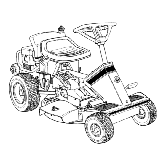
BLADE PEDALS FIGURE 1.1 1.2 NOMENCLATURE The nomenclature drawing above, Figure 1.1, shows the essential parts of the SNAPPER Rear Engine Rider. It is recommended that all operator’s of this equipment become thoroughly components, and operation of this machine before operating. -
Page 6: Section 2 - Operating Instructions
Section 2 - OPERATING INSTRUCTIONS 2.1 PRE-START CHECK LIST Make the following checks and perform the service required before each start-up. 2.1.1. Check tires and add or release air as needed to bring pressure to 12 psi in front and 12 psi in rear tires. -
Page 7: Starting & Stopping Engine, Blade & Wheel Drive
Section 2 - OPERATING INSTRUCTIONS 2.3 STARTING & OPERATION 2.3.1. ENGINE (ELECTRIC START) IMPORTANT: When the ignition key is turned to “START”, the engine will turn over, but will not start unless the Clutch/Brake pedal is pressed all the way down, the Blade Lever is in the “OFF”... -
Page 8: Parking Brake
Section 2 - OPERATING INSTRUCTIONS 2.3 STARTING & OPERATION 2.3.1. ENGINE (ELECTRIC START) (Continued) 8. Should the battery be too weak to start the engine, Refer to Section “ENGINE (MANUAL START)” to manually start the electric start engines. 9. On Model 331418BVE, the engine is equipped with a fuel shut-off solenoid. -
Page 9: Starting & Stopping Mower Blades
3 seconds, the blade brake must be adjusted. Refer to Section “BLADE BRAKE ADJUSTMENT” for adjustment procedures or return machine to an authorized SNAPPER dealer for adjustment. DO NOT CONTINUE to operate machine until blade brake is adjusted and functioning properly. - Page 10 3 seconds, the blade brake must be adjusted. Refer to Section “BLADE BRAKE ADJUSTMENT” for adjustment procedures or return machine to an authorized SNAPPER dealer for adjustment. DO NOT CONTINUE to operate machine until blade brake is adjusted and functioning properly.
-
Page 11: Cutting Height Adjustment
Section 2 - OPERATING INSTRUCTIONS 2.4 STOPPING - ENGINE, WHEEL DRIVE, BLADE 2.4.4. PARK BRAKE 1. Engage park brake by pushing clutch/brake pedal “DOWN” and moving the park brake lever to the “ON” position. While holding the park brake lever “ON”, release clutch/brake pedal to set park brake. -
Page 12: Reverse Lockout Mechanism
DO NOT operate machine if Reverse Lockout Mechanism is not functioning properly. Contact your local Snapper dealer for assistance. Reverse Lockout Mechanism Override Stop machine. Stop blade. Depress and hold Override Lever. -
Page 13: Section 3 - Maintenance Instructions
SNAPPER dealer annually for inspection and addition of any new devices which might upgrade the safety of the Rear Engine Rider. For the nearest SNAPPER dealer in your area, check the yellow pages under the heading LAWN MOWERS. For engine parts and service, look for the engine manufacturer’s dealers... -
Page 14: Check Blade Drive Belt
2. The operator leaves the operator position with Blade Control “ON” and/or clutch/brake pedal is released. DO NOT operate machine if interlock system is not functioning properly. Contact your SNAPPER dealer immediately for assistance. 28” , 30” & 33” MODELS... -
Page 15: Reverse Lockout Mechanism
3. Shift lever must not go into reverse. WARNING DO NOT operate machine if Reverse Lockout Mechanism is not functioning properly. Contact your SNAPPER dealer immediately for assistance. 3.2.9. LUBRICATION – GREASE FITTINGS The following components on the Rear Engine Rider are equipped with grease fittings and require periodic lubrication. -
Page 16: Front Wheel Bearing - Lubrication
Section 3 - MAINTENANCE WARNING DO NOT attempt any adjustments, maintenance or service with the engine or blades running. Stop blades. Stop engine. Engage parking brake. Remove key. Remove spark plug wires from spark plugs and (gas only) secure wires away from spark plugs. Engine and components are HOT. -
Page 17: Service - Annually
Figure 3.9. 4. To check lubricant in chain case, remove fill/level plug and look for lubricant on the internal components of the chain case. If no lubricant is visible, add SNAPPER transmission grease as needed. See Figure 3.9. CHAIN CASE... -
Page 18: Removing Fuel Tank
Section 3 – MAINTENANCE 3.7 REMOVING FUEL TANK Before removing fuel tank from rear engine rider, move rider outdoors where fumes can be easily dissipated. Removal of the tank is accomplished from the left side of the machine by pulling the tank straight up and away from the fuel tank bracket. -
Page 19: Section 4- Adjustments And Repair
However, if there is difficulty in achieving these adjustments and repairs, it is recommended that these repairs be made by an authorized SNAPPER dealer. WARNING Once blade is disengaged it should come to a stop in 3 seconds or less. -
Page 20: Mower Deck Adjustment (Side To Side Levelness)
Section 4 - ADJUSTMENTS & REPAIR WARNING DO NOT attempt any adjustments, maintenance, service or repairs with the engine running. STOP engine. STOP blade. Engage parking brake. Remove key. Remove spark plug wire from spark plug and secure away from plug. Engine and components are HOT. -
Page 21: Cutting Height Adjustment
Lift quadrant in highest position gives 1-1/2” to 4” cutting height range. 4.3 REAR ENGINE RIDER DRIVE COMPONENTS Your Snapper rider is equipped with a patented smooth start clutch. The clutch should operate smoothly and provide ample traction. If problems are experienced, contact your Snapper dealer for repair. - Page 22 Section 4 - ADJUSTMENTS & REPAIR WARNING DO NOT attempt any adjustments, maintenance, service or repairs with the engine running. STOP engine. STOP blade. Engage parking brake. Remove key. Remove spark plug wire from spark plug and secure away from plug. Engine and components are HOT.
-
Page 23: Mower Blade Replacement
Section 4 - ADJUSTMENTS & REPAIR WARNING DO NOT attempt any adjustments, maintenance, service or repairs with the engine running. Stop engine. Stop blade. Engage parking brake. Remove key. Remove spark plug wire from spark plug and secure away from plug. Engine and components are HOT. -
Page 24: Mower Drive Belt Removal/Replacement
Section 4 - ADJUSTMENTS & REPAIR WARNING DO NOT attempt any adjustments, maintenance, service or repairs with the engine running. STOP engine. STOP blade. Engage parking brake. Remove key. Remove spark plug wire from spark plug and secure away from plug. Engine and components are HOT. -
Page 25: Battery Removal, Replacement, Service
Section 4 - ADJUSTMENTS & REPAIR WARNING DO NOT attempt any adjustments, maintenance, service or repairs with the engine running. Stop engine. Stop blade. Engage parking brake. Remove key. Remove spark plug wire from spark plug and secure away from plug. Engine and components are HOT. - Page 26 Section 4 - ADJUSTMENTS & REPAIR WARNING The electrolyte (acid) produces a highly explosive gas. Keep all sparks, flame and fire away from area when charging battery or when handling electrolyte or battery. Electrolyte (acid) is a highly corrosive liquid. Wear eye protection.
-
Page 27: Accessories
100% Charged 75% Charged 50% Charged 25% Charged 0% Charged SNAPPER REAR ENGINE RIDER ACCESSORIES PART NO. DESCRIPTION OF KIT 6-0517... Wheel Weight (8” Wheels) ... All Rear Engine Riders 6-0601... Smooth Start Clutch... All Rear Engine Riders 6-0697... Dump Cart... All Rear Engine Riders 6-1400... -
Page 28: Troubleshooting
1. Fill fuel tank with fresh fuel to proper level. 2. Move choke control to “CHOKE” position. 3. Place spark plug wire onto spark plug. 4. Contact authorized SNAPPER dealer. 5. Engage park brake. 6. Turn ignition switch to the RUN position. - Page 29 PROBABLE CAUSE CORRECTIVE ACTION 1. Replace drive disc. 2. Adjust rubber drive disc. 3. Replace with SNAPPER tapered bolt & nut. 4. Contact authorized SNAPPER dealer. 5. Contact authorized SNAPPER dealer. 1. Move lever to the “ON” position. 2. Adjust or replace mower belt.
-
Page 30: Maintenance Schedule
SUBJECT SERVICE TO BE PERFORMED Engine Check Oil Level Engine Initial Oil Change Engine Periodic Oil Change Air Pre-Cleaner Service Sponge Pre- Cleaner Element Air Cleaner Replace Element Spark Plug Replace Plugs Fuel Filter Replace Filter Engine Cooling Clean Shrouds & Fins System Battery Check Electrolyte... -
Page 31: Maintenance/Replacement Parts
MAINTENANCE/REPLACEMENT PARTS MAINTENANCE PARTS Engine Speed Control (Briggs Engine) Engine Speed Control (Kohler Engine) Clutch/Brake Cable Brake Cable 28” Cutter Blade (Standard - Not Air Lift Compatible) 28” Cutter Blade (Standard - Air Lift Compatible) 28” Cutter Blade (Mulching) 28” Cutter Blade (Ninja - Quad Edge) 30”... -
Page 32: Warranty
For three (3) years from purchase date for the original purchaser's residential, non-commercial use, SNAPPER, through any authorized SNAPPER dealer will replace, free of charge (except for taxes where applicable), any part or parts found upon examination by the factory at McDonough, Georgia, to be defective in material or workmanship or both. -
Page 33: Primary Maintenance
PRIMARY MAINTENANCE... - Page 34 PRIMARY MAINTENANCE...
- Page 35 PRIMARY MAINTENANCE...
-
Page 36: Primary Maintenance
PRIMARY MAINTENANCE... - Page 37 SERVICE NOTES ______________________________________________________________________________ ______________________________________________________________________________ ______________________________________________________________________________ ______________________________________________________________________________ ______________________________________________________________________________ ______________________________________________________________________________ ______________________________________________________________________________ ______________________________________________________________________________ ______________________________________________________________________________ ______________________________________________________________________________ ______________________________________________________________________________ ______________________________________________________________________________ ______________________________________________________________________________ ______________________________________________________________________________ ______________________________________________________________________________ ______________________________________________________________________________ ______________________________________________________________________________ ______________________________________________________________________________ ______________________________________________________________________________ ______________________________________________________________________________ ______________________________________________________________________________ ______________________________________________________________________________ ______________________________________________________________________________ ______________________________________________________________________________ ______________________________________________________________________________ ______________________________________________________________________________ ______________________________________________________________________________ ______________________________________________________________________________ ______________________________________________________________________________ ______________________________________________________________________________ ______________________________________________________________________________ ______________________________________________________________________________ ______________________________________________________________________________ ______________________________________________________________________________ ______________________________________________________________________________ ______________________________________________________________________________ ______________________________________________________________________________ ______________________________________________________________________________ ______________________________________________________________________________ ______________________________________________________________________________ ______________________________________________________________________________...
- Page 38 Read, Understand, and Follow all warnings and instructions in this manual, the engine manual, and on the machine, engine and attachments. If you have any questions about your Snapper product, contact your local authorized Snapper dealer or contact Snapper Customer Service at Snapper, McDonough, GA.