Table of Contents
Advertisement
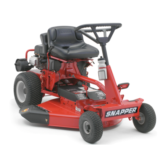
Safety Instructions & Operator's Manual for
REAR ENGINE RIDING MOWER
SERIES 23
MODELS
281123BV
281223BVE
281123HVE
281323BVE
2813523BVE
301123BV
301223BVE
301323BVE
3013523BVE
331323HVE
331523KVE
331623BVE
MODEL
NUMBER
EXPLANATION
3UTTING WIDTH
ENGINE HP
3ERIES DESIGNATION
,
Y,
ENGINE OPTIONS
ENGINE TYPE
ENGINE MODEL
28- 28" Cutting Deck
30-30"
Cutting Deck
33- 33" Cutting Deck
11 - 11,0 HP Engine
12 - 12.0 HP Engine
13 - 13,0 HP Engine
135- 13.5 HP Engine
15 - 15.0 HP Engine
16 - 16.0 HP Engine
23- Series Designation
B - Briggs Engine
K - Kohler Engine
H - Honda Engine
V- Over Head Valve
E - Electric Start
Thank you for buying a SNAPPER Product!
Before operating your machine, read this manual carefully and pay
particular attention to the "IMPORTANT
SAFETY INSTRUCTIONS"
on Pages 2 thru 4. Remember that all power
equipment
can be dangerous
if used improperly.
Also keep in mind that SAFETY
requires careful use in
accordance with the operating instructions and common sense!
COPYRIGHT
© 2003
SNAPPER
PRODUCTS
iNC.
ALL RIGHTS RESERVED
SNAPPER
McDonough,
GA., 30253
U.S.A.
MANUAL No. 7-5741 (I.R. 5/20/03)
Advertisement
Table of Contents

Related Manuals for Snapper 281323BVE


Summary of Contents for Snapper 281323BVE
- Page 1 13 - 13,0 HP Engine H - Honda Engine 135- 13.5 HP Engine 15 - 15.0 HP Engine Thank you for buying a SNAPPER Product! Before operating your machine, read this manual carefully and pay particular attention to the "IMPORTANT SAFETY INSTRUCTIONS"...
- Page 2 Customer Service Department at SNAPPER, McDonough, Georgia 30253. Phone: (1-800-935-2967). PROTECTION FOR CHILDREN PROTECTION AGAINST TIPOVERS Tragic accidents can occur if the operator is not alert to the (Continued From Previous Column) presence of children.
- Page 3 Always place the containers on the ground loads to hitch plate as specified with SNAPPER away from the vehicle before filling. attachment instructions. Remove gas-powered equipment from 15.
- Page 4 14. Have machine serviced authorized SNAPPER dealer at least once a year and have the dealer install any new safety devices. 15. Use only genuine SNAPPER replacement parts assure that original standards maintained.
-
Page 5: Table Of Contents
PARTS ..............WARRANTY ........................PRIMARY MAINTENANCE ..................34-37 PRODUCT REGISTRATION FORM ................IMPORTANT: The figures and illustrations in this manual are provided for reference only and may differ from your specific model. Contact your Snapper dealer if you have questions. -
Page 6: Important Safety Instructions
This manual has been prepared for the operator's of the The nomenclature drawing above, Figure 1.1, shows the SNAPPER Rear Engine Rider. Its purpose, aside from essential parts of the SNAPPER Rear Engine Rider. It is recommending standard operating procedures... -
Page 7: Section 2 - Operating Instructions
Section 2 -OPERATING INSTRUCTIONS PRE-START CHECK LIST OPERATOR'S SEAT ADJUSTMENT Make the following checks and perform the service 2.2.1. FRONT TO REAR ADJUSTMENT required before each start-up. 1. With the engine stopped, loosen the two adjusting 2.1.1. Check tires and add or release air as needed knobs and move seat to desired position. - Page 8 Section 2 -OPERATING INSTRUCTIONS STARTING & OPERATION TO START ENGINE, 2.3.1. ENGINE (ELECTRIC START) PUSH CLUTCH/BRAKE IMPORTANT: When the ignition key is turned to PEDAL ALL THE WAY "START", the engine will turn over, but will not start unless the Clutch/Brake pedal is pressed all the way DOWN down, the Blade Lever is in the "OFF"...
-
Page 9: Parking Brake
Section 2 -OPERATING INSTRUCTIONS STARTING & OPERATION 4. Open vent fuel filler turning 2.3.1. ENGINE (ELECTRIC START) (Continued) counterclockwise. NOTE: Failure to open vent on 8. Should the battery be too weak to start the engine, the fuel filler cap can cause engine to stall. refer to Section "ENGINE (MANUAL START)"... - Page 10 3 seconds, the blade brake and hazards before and while backing. must be adjusted. Refer to Section "BLADE BRAKE ADJUSTMENT" for adjustment procedures or return machine to an authorized SNAPPER dealer DEPRESS adjustment. DO NOT CONTINUE to operate machine PEDAL until blade brake adjusted functioning properly.
- Page 11 3 seconds, the blade brake must be adjusted.Refer to Section "BLADE BRAKE ADJUSTMENT" foradjustment procedures or return machine to an authorized SNAPPER dealer for adjustment.DO NOT CONTINUE to operate machine until blade brake is adjusted and functioning properly.
-
Page 12: Cutting Height Adjustment
Section 2 -OPERATING INSTRUCTIONS 2.5. CUTTING HEIGHT ADJUSTMENT STOPPING - ENGINE, WHEEL DRIVE, BLADE 2.4.4. PARK BRAKE 1. Adjust cutting height as desired to any one of 1. Engage park brake by pushing clutch/brake pedal five positions using deck lift lever. Move deck lift "DOWN"... -
Page 13: Reverse Lockout Mechanism
DO NOT operate machine if Reverse Lockout and while backing. Mechanism is not functioning properly. Contact your local Snapper dealer for assistance. We realize that this could cause a change to your previous mowing method... -
Page 14: Section 3 - Maintenance Instructions
Rear Engine Rider on rear the safety of the Rear Engine Rider. For the nearest bumper. SNAPPER dealer in your area, check the yellow pages under the heading LAWN MOWERS. For engine parts and service, look for the engine... -
Page 15: Check Blade Drive Belt
Refer to Section should be 1-1/4" but no less 1", If the measurement "BLADE BRAKE ADJUSTMENT" contact your is less than 1", the belt tension should be adjusted, SNAPPER dealer for assistance. Refer Section "BLADE DRIVE BELT ADJUSTMENT", 3.2.6. SERVICE BRAKE / PARK BRAKE Check machine brake for proper function. -
Page 16: Reverse Lockout Mechanism
WARNING DO NOT operate machine if interlock system is not appear clean. Remove filter and pre-cleaner functioning properly, Contact your SNAPPER dealer I inspection. immediately for assistance, BRIGGS ENGINE SHOWN AIR CLEANER LATCH SERVICE - AFTER FIRST 5 HOURS 3.2.7. -
Page 17: Service - Every 25 Operating Hours
Section 3 - MAINTENANCE SPINDLE GREASE DO NOT attempt any adjustments, maintenance FITTING service with the engine or blades running. Stop blades. Stop engine. Engage parking brake. Remove key. Remove spark plug wires from spark plugs and (gas only) secure wires away from spark plugs. -
Page 18: Rear Axle Bearing - Lubrication
If no lubricant is visible, add SNAPPER transmission grease needed. See Figure 3.9. AXLE BOOTS FIGURE 3.7 3.3.9. DIFFERENTIAL/CHAIN CASE - LUBRICATION 1. -
Page 19: Service -Annually
Remove spark plug wire from spark plug and genuine SNAPPER replacement parts available from an authorized SNAPPER dealer. secure away from plug. Engine and components are HOT. Avoid serious burns, allow all parts to 3.5.1. All bushings and pivot areas. -
Page 20: Section 4- Adjustments And Repair
Snapper dealer. HOT. Avoid serious burns, allow allparts to cool beforeworking on machine. Fuel Filler C ap and Vent 3" to 3-1/4" must be closed securelyto preventfuelspillage. CLEARANCE 4.1 ENGINE ADJUSTMENTS... -
Page 21: Mower Deck Adjustment (Side To Side Levelness)
Section 4 - ADJUSTMENTS & REPAIR 7. Move lift arm up or down as required until blade WARNING tips are within 1/8" of each other. See Figure 4.3. attempt any adjustments, maintenance, 8. Tighten shoulder bolt & nut loosened in Step 6. Recheck both sides of deck for correct levelness. -
Page 22: Mower Drive Belt Adjustment - 28" & 30" Decks
Make sure hardware is tightened securely. IMPORTANT: The SNAPPER Rear Engine Rider Models with 33" decks do not require belt tension adjustment. But, if front frame assembly clamp is loosened for any reason, recheck belt spacing between idler pulley and belt. With blade lever in the "ON"... -
Page 23: Rear Engine Rider Drive Components
If problems are experienced, contact your Snapper dealer for repair. 4.3.1 SERVICE BRAKE/PARK BRAKE ADJUSTMENT CABLE Test the wheel brake on a dry concrete surface. HOUSING When properly adjusted, the Rear Engine Rider will stop within 5 feet from fastest speed. -
Page 24: Mower Blade Replacement
Section 4 - ADJUSTMENTS & REPAIR 5. Inspect condition of blade. See Figure 4.11. WARNING 6. If blade is in good condition, sharpen at 22 to 28 DO NOT attempt adjustments, maintenance, degrees. DO NOT sharpen beyond existing cutting service or repairs with the engine running. - Page 25 Section 4 - ADJUSTMENTS & REPAIR 9. Route belt onto spindle pulley. Make sure belt is WARNING inside spindle belt guide and idler belt guide. Route attempt any adjustments, maintenance, belt as shown in Figure 4.15 or 4.16. 10. Reinstall idler removed in Step 8. The idler belt service or repairs with the engine running.
- Page 26 Section 4 - ADJUSTMENTS & REPAIR WARNING POSITIVE TERMINAL POSITIVE (+) INSULATOR attempt any adjustments, maintenance, CABLE "'- service or repairs with the engine running. Stop engine. Stop blade.Engage parking brake. Remove key. Remove spark plug wire from spark plug and BLACK secure away from plug.Engine and components are NEGATIVE (-)
- Page 27 Section 4 - ADJUSTMENTS & REPAIR WARNING WARNING The electrolyte (acid) produces a highly explosive gas. DO NOT attempt to charge battery while installed Keep all sparks, flame and fire away from area when the Riding Mower. DO NOT use "BOOST" chargers on charging battery or when...
-
Page 28: Accessories
1.120 11.90v 25% Charged One Ball Floating Less than 1.100 Less than 11.80v 0% Charged Zero Balls Floating SNAPPER REAR ENGINE RIDER ACCESSORIES DESCRIPTION OF KIT MODELS USED ON PART 6-0517 . Wheel Weight (8" Wheels) ....... All Rear Engine Riders 6-0601 . -
Page 29: Troubleshooting
3. Spark plug wire disconnected. 3. Place spark plug wire onto spark plug. 4. Faulty parking brake, blade or ignition switch. 4. Contact authorized SNAPPER dealer. 5. Park brake not engaged. 5. Engage park brake. 6. Ignition is in the OFF position. - Page 30 2. Rubber drive disc is not tracking properly on Adjust rubber drive disc. drive disc. 3. Tapered axle bolt and nut missing. Replace with SNAPPER tapered bolt & nut. Contact authorized SNAPPER dealer. 4. Axle bearing seized. 5. Insufficient lubrication in chain case or Contact authorized SNAPPER dealer.
-
Page 31: Maintenance Schedule
MAINTENANCE SCHEDULE SUBJECT SERVICE REFERENCE EACH EACH HOURS HOURS HOURS SEASON PAGES TO BE PERFORMED HOURS Check Oil Level Engine Page 7 Engine Initial Oil Change Page 14 Engine Periodic Oil Change Page 16 Air Pre-Cleaner Service Sponge Pre- Engine Manual Cleaner Element Air Cleaner Replace Element... -
Page 32: Maintenance/Replacement Parts
MAINTENANCE/REPLACEMENT PARTS MAINTENANCE PARTS Engine Speed Control (Briggs Engine) 2-2751 Engine Speed Control (Kohler Engine) 7-4320 Engine Speed Control (Honda Engine) 7-5089 Clutch/Brake Cable 2-2449 Clutch/Brake Cable (33" Deck Models Only) 7-4131 Brake Cable 7-2648 28" Cutter Blade (Standard - Not Air Lift Compatible) 3-5635 28"... -
Page 33: Warranty
Batteries have a one (1) year warranty period with free replacement if required for one (1) year from the original purchase date. SNAPPER will not be responsible for any installation cost incurred. The battery warranty only covers original equipment batteries and does not cover damage... -
Page 34: Primary Maintenance
PRIMARY MAINTENANCE ® illustration how dirt can & how maintenance can protect it! Snapper uses the best avail- engines and components In their products in order to provide long, satisfactory service. However, proper • care Is essential In _'" prolonging engine life. Dirt... - Page 35 Because of its working environ- ment, the air available to your Snapper engine Is " heavily saturated with air- borne dirt particles. As the dirt particles are stopped, Damage caused by a poorly serviced air...
- Page 36 PRIMARY MAINTENANCE Air Is also needed to keep your engine cool. Dirt, dust & debris build up to restrict and clog cooling air Intake screens and fins. Clean screens and fins at frequent Intervals. The engine blower housing and shrouds should be removed at least once each season or more often i under dry, dusty condlUons...
- Page 37 2-cycle engine fuel, be sure the containers are clearly marked to avoid mix-up. Snapper 2-cycle engines require a 32 to 1 mixture of gasoline and BIA certified TC-W oil such as Snapper's 2-cycle engine oil Many of the 2-cycle engine oils on the...
-
Page 38: Product Registration Form
You can contact us at our web site or if you would like to speak with a Customer Service Representative. Call us at the Snapper Customer Relations Center. faster service please have your Serial Number and Model Number available. - Page 39 NOTES...
- Page 40 NOTES...
- Page 41 Safety Instructions & Operator's Manual for REAR ENGINE RIDING MOWER SERIES 23 IMPORTANT Snapper products are built using engines that meet or exceed all applicable emissions requirements on the date manufactured. The labels on those engines contain very important emissions...