Table of Contents
Advertisement
Chapter 1. Getting Started .................................................................................... 1-1
Mainboard Specifications ................................................................................... 1-2
Mainboard Layout ................................................................................................ 1-4
Chapter 2. Hardware Setup .................................................................................. 2-1
Quick Components Guide .................................................................................... 2-2
CPU (Central Processing Unit) ............................................................................ 2-2
Introduction to LGA 775 CPU ...................................................................... 2-3
CPU & Cooler Installation ............................................................................. 2-4
Memory ................................................................................................................. 2-7
Installing DDRII Modules ............................................................................... 2-7
Power Supply ...................................................................................................... 2-8
ATX 24-Pin Power Connector: ATX1 ......................................................... 2-8
ATX 12V Power Connector: JPW 1 ............................................................ 2-8
Back Panel ............................................................................................................ 2-9
Connectors ......................................................................................................... 2-11
Floppy Disk Drive Connector: FDD1 ........................................................... 2-11
ATA133 Hard Disk Connectors: IDE1 & IDE2 ............................................ 2-11
Serial ATA Connectors: SATA1, SATA2 ................................................... 2-12
BIOS Password Clear: JPWD1 .................................................................. 2-12
Fan Power Connectors: CPU_FAN1, SYS_FAN1 ................................... 2-13
Front USB Connectors: JUSB1, JUSB2 ................................................... 2-13
SPDIF-Out Connector: SPDOUT1 ............................................................. 2-14
Front Panel Audio Connector: JAUD1 ...................................................... 2-14
BIOS Flash Write Protection: JW P1 .......................................................... 2-14
IEEE 1394 Connectors: J1394_1 .............................................................. 2-15
Front Panel Connectors: JFP1/JFP2 ......................................................... 2-15
Clear CMOS Jumper: JBAT1 ..................................................................... 2-16
BIOS Recovery: JBR1 ............................................................................... 2-16
Jumpers .............................................................................................................. 2-16
Slots .................................................................................................................... 2-17
PCI (Peripheral Component Interconnect) Express Slots ....................... 2-17
PCI (Peripheral Component Interconnect) Slots ...................................... 2-17
PCI Interrupt Request Routing ................................................................... 2-18
Chapter 3. BIOS Setup ............................................................................................ 3-1
Entering Setup ..................................................................................................... 3-2
Control Keys ................................................................................................ 3-3
Getting Help .................................................................................................. 3-3
CONTENTS
i
Advertisement
Table of Contents

Related Manuals for MSI MS-7293 Series


Summary of Contents for MSI MS-7293 Series
-
Page 1: Table Of Contents
CONTENTS Chapter 1. Getting Started ..................1-1 Mainboard Specifications ................... 1-2 Mainboard Layout ....................1-4 Chapter 2. Hardware Setup .................. 2-1 Quick Components Guide ..................2-2 CPU (Central Processing Unit) ................2-2 Introduction to LGA 775 CPU ..............2-3 CPU & Cooler Installation ................2-4 Memory ......................... - Page 2 General Help <F1> ..................3-3 The Main Menu ..................... 3-4 Standard CMOS Features ................... 3-6 Advanced BIOS Features ................... 3-8 Advanced Chipset Features ................3-10 Integrated Peripherals ..................3-13 Power Management Setup ................3-15 PNP/PCI Configurations ..................3-18 H/W Monitor ......................3-19 Load Optimized Defaults ...................
-
Page 3: Chapter 1. Getting Started
Getting Started Chapter 1 Getting Started Thank you for choosing the MS-7293 Series (MS-7293 v2.X) Micro ATX mainboard. The MS-7293 Series ® ® mainboards are based on VIA PT890 & VIA 8237A chipsets for optimal system efficiency. Designed to fit ®... -
Page 4: Mainboard Specifications
M S-7293 M ainboard Mainboard Specifications Processor Support ® - Supports Intel Pentium 4, Pentium D, Celeron D ® and intel Core 2 Duo processors in the LGA775 package. - Supports 3/4 pin CPU Fan Pin-Header with Fan Speed Control. - Supports EIST Technology - Supports Hyper-Threading (HT) Technology - Supports Intel Dual Core Technology... - Page 5 Getting Started Connectors Backpannel - 1 serial port (COM1) - 1 IEEE 1394 port - 4 USB 2.0 Ports - 1 LAN jack - 6 flexible audio jacks - 1 SPDIF Out connector On-Board Pinheaders - 1 front Audio pinheader - 1 SPDIF-out pinheader - 1 IEEE 1394 pinheaders - 2 USB 2.0 pinheaders...
-
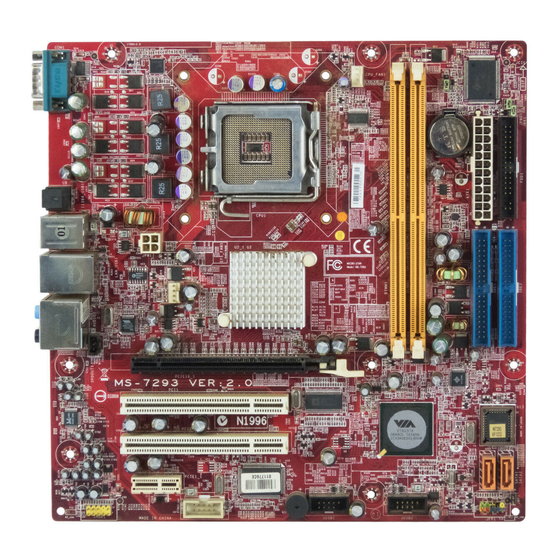
Page 6: Mainboard Layout
M S-7293 M ainboard Mainboard Layout COM Port SPDIFOUT1 Top:1394 Bottom: U SB ports Top: LAN Jack Bottom: U SB ports PT890 Line-In Line-Out T:RS-Out M:CS-Out B:SS-Out PCIE16_1 SPDOUT1 PCI1 VT8237A PCI2 PCIE1_1 1394 Chip J1394_1 JUSB1 JUSB2 JFP1 JAUD1 MS-7293 v2.X M-ATX Mainboard... -
Page 7: Chapter 2. Hardware Setup
Hardware Setup Chapter 2 Hardware Setup This chapter provides you with the information about hardware setup procedures. While doing the installation, be careful in holding the components and follow the installation procedures. For some components, if you install in the wrong orientation, the components will not work properly. -
Page 8: Quick Components Guide
M S-7293 M ainboard Quick Components Guide CPU_FAN1, p.2-13 JPW1, p.2-8 DDRII DIMMs, p.2-7 SYS_FAN1, p.2-13 JBAT1, p.2-16 SPDOUT1, p.2-14 CPU, p.2-3 JPWD1, p.2-12 JBR1, p.2-16 Back Panel FDD1, p.2-11 I/O, p.2-9 ATX1, p.2-11 IDE1/2, p.2-12 PCIE Slot, p.2-17 PCI Slots, p.2-17 SATA1/2, p.2-12 PCIE Slot, p.2-17... -
Page 9: Cpu (Central Processing Unit)
CPU, make sure to install the cooler to prevent overheating. If you do not have the CPU cooler, contact your dealer to purchase and install them before turning on the computer. For the latest information about CPU, please visit http://www.msi.com.tw/program/ products/mainboard/mbd/pro_mbd_cpu_support.php. Important 1. -
Page 10: Cpu & Cooler Installation
M S-7293 M ainboard CPU & Cooler Installation W hen you are installing the CPU, make sure the CPU has a cooler at- tached on the top to prevent overheating. If you do not have the cooler, contact your dealer to purchase and install them before turning on the computer. Meanwhile, do not forget to apply some silicon heat transfer compound on CPU before installing the heat sink/cooler fan for better heat dispersion. - Page 11 Hardware Setup Important 1. Confirm if your CPU cooler is firmly installed before turning on your system. 2. Do not touch the CPU socket pins to avoid damaging. 3. The availability of the CPU land side cover depends on your CPU packing. 5.
- Page 12 M S-7293 M ainboard 9. Press down the load lever lightly 10. Align the holes on the mainboard onto the load plate, and then se- with the heatsink. Push down the cure the lever with the hook under c ooler u nti l i ts f ou r c lip s g et retention tab.
-
Page 13: Memory
Hardware Setup Memory The mainboard provides two 240-pin non-ECC DDRII DIMM slots. For more information on compatible components, please visit http://www.msi.com.tw/ program/products/mainboard/mbd/pro_mbd_trp_list.php. DDRII 240-pin, 1.8V 64x2=128 pin 56x2=112 pin Installing DDRII Modules 1. The memory module has only one notch on the center and will only fit in the right orientation. -
Page 14: Power Supply
M S-7293 M ainboard Power Supply ATX 24-Pin Power Connector: ATX1 pin 13 This connector allows you to connect an ATX 24-pin power supply. To connect the ATX 24-pin power supply, make sure the plug of the power supply is inserted in the proper orientation and the pins are aligned. -
Page 15: Back Panel
Hardware Setup Back Panel L-In RS-Out 1394 Port Serial Port L-Out USB Ports CS-Out SPDIF-Out SS-Out Serial Port Connector The serial port is a 16550A high speed communications port that sends/ receives 16 bytes FIFOs. You can attach a serial mouse or other serial devices directly to the connector. - Page 16 M S-7293 M ainboard Optical SPDIF-Out connector This SPDIF (Sony & Philips Digital Interconnect Format) connector is provided for digital audio transmission to external speakers through an optical cable. Audio Port Connectors These audio connectors are used for audio devices. You can differentiate the color of the audio jacks for different audio sound effects.
-
Page 17: Connectors
Hardware Setup Connectors Floppy Disk Drive Connector: FDD1 This standard FDD connector supports 360K, 720K, 1.2M, 1.44M and 2.88M floppy disk types. FDD1 ATA133 Hard Disk Connectors: IDE1 & IDE2 The mainboard has a 32-bit Enhanced PCI IDE and Ultra DMA 66/100/133 controller that provides PIO mode 0~4, Bus Master, and Ultra DMA 66/100/133 function. -
Page 18: Serial Ata Connectors: Sata1, Sata2
M S-7293 M ainboard Serial ATA Connectors: SATA1, SATA2 SATA1, SATA2 are high-speed Serial ATA interface ports. Each supports 1 genera- tion serial ATA data rates of 150MB/s and is fully compliant with Serial ATA 1.0 specifications. Each Serial ATA connector can connect to 1 hard disk device. SATA1, SATA2 Pin Definition SIGNAL SIGNAL... -
Page 19: Fan Power Connectors: Cpu_Fan1, Sys_Fan1
Hardware Setup Fan Power Connectors: CPU_FAN1, SYS_FAN1 CONTROL The fan power connectors support system cooling fan with +12V. SENSOR W hen connecting the wire to the connectors, always take note +1 2V that the red wire is the positive and should be connected to the +12V, the black wire is Ground and should be connected to GND. -
Page 20: Spdif-Out Connector: Spdout1
M S-7293 M ainboard SPDOUT1 SPDIF-Out Connector: SPDOUT1 This connector is used to connect SPDIF (Sony & Philips Digital Interconnect Format) interface for digital audio transmission. SPDIF Front Panel Audio Connector: JAUD1 The JAUD1 front panel audio connector allows you to connect the front panel audio ®... -
Page 21: Ieee 1394 Connectors: J1394_1
Hardware Setup IEEE 1394 Connectors: J1394_1 The mainboard provides IEEE1394 pinheaders that allow you to connect IEEE 1394 ports via an external IEEE1394 bracket (optional). Pin Definition SIGNAL SIGNAL TPA+ TPA- Ground Ground TPB+ TPB- J1394_1 Cable power Cable power Key (no pin) Ground Front Panel Connectors: JFP1... -
Page 22: Clear Cmos Jumper: Jbat1
M S-7293 M ainboard Jumpers Clear CMOS Jumper: JBAT1 There is a CMOS RAM onboard that has a power supply from external battery to keep the data of system configuration. With the CMOS RAM, the system can automatically boot OS every time it is turned on. If you want to clear the system configuration, set the JBAT1 (Clear CMOS Jumper ) to clear data. -
Page 23: Slots
Hardware Setup Slots PCI (Peripheral Component Interconnect) Express Slots PCI Express architecture provides a high performance I/O infrastructure for Desktop Platforms with transfer rates starting at 2.5 Giga transfers per second over a PCI Express x1 lane for Gigabit Ethernet, TV Tuners, 1394 controllers, and general pur- pose I/O. -
Page 24: Pci Interrupt Request Routing
M S-7293 M ainboard PCI Interrupt Request Routing The IRQ, acronym of interrupt request line and pronounced I-R-Q, are hardware lines over which devices can send interrupt signals to the microprocessor. The PCI IRQ pins are typically connected to the PCI bus pins as follows: Order 1 Order 2 Order 3... -
Page 25: Chapter 3. Bios Setup
BIOS Setup Chapter 3 BIOS Setup This chapter provides information on the BIOS Setup program and allows you to configure the system for optimum use. You may need to run the Setup program when: ² An error message appears on the screen during the system booting up, and requests you to run SETUP. -
Page 26: Entering Setup
M S-7293 M ainboard Entering Setup Power on the computer and the system will start POST (Power On Self Test) process. W hen the message below appears on the screen, press <DEL> key to enter Setup. Press DEL to enter SETUP If the message disappears before you respond and you still wish to enter Setup, restart the system by turning it OFF and On or pressing the RESET button. -
Page 27: Control Keys
BIOS Setup Control Keys < ↑> Move to the previous item < ↓> Move to the next item < ←> Move to the item in the left hand < →> Move to the item in the right hand <Enter> Select the item Jumps to the Exit menu or returns to the main menu from a <Esc>... -
Page 28: The Main Menu
M S-7293 M ainboard The Main Menu Standard CM OS Features Use this menu for basic system configurations, such as time, date etc. Advanced BIOS Features ® Use this menu to setup the items of AMI special enhanced features. Advanced Chipset Features Use this menu to change the values in the chipset registers and optimize your system’s performance. - Page 29 BIOS Setup Load Optimized Defaults Use this menu to load the default values set by the mainboard manufacturer specifi- cally for optimal performance of the mainboard. Set Supervisor Password Use this menu to set the supervisor password for BIOS. Set User Password Use this menu to set the user password for BIOS.
-
Page 30: Standard Cmos Features
M S-7293 M ainboard Standard CMOS Features The items in Standard CMOS Features Menu includes some basic setup items. Use the arrow keys to highlight the item and then use the <PgUp> or <PgDn> keys to select the value you want in each item. Date (mm:dd:yy) This allows you to set the system to the date that you want (usually the current date). - Page 31 BIOS Setup Important IDE Channel 0/1/2/3 Master/ Slave are appearing when you connect the HD devices to the SATA connector on the mainboard. Drive A This item allows you to set the type of floppy drives installed. Halt On The setting determines whether the system will stop if an error is detected at boot. Available options are: [No Errors] The system doesn’t stop for any detected error.
-
Page 32: Advanced Bios Features
M S-7293 M ainboard Advanced BIOS Features Quick Booting Setting the item to [Enabled] allows the system to boot within 10 seconds since it will skip some check items. Boot Up Num-Lock LED This setting is to set the Num Lock status when the system is powered on. Setting to [On] will turn on the Num Lock key when the system is powered on. - Page 33 BIOS Setup S3 HDD Security FreezeLock This field allows you to enable or disable the HDD security in S3. MPS Table Version This field allows you to select which MPS (Multi-Processor Specification) version to be used for the operating system. You need to select the MPS version supported by your operating system.
-
Page 34: Advanced Chipset Features
M S-7293 M ainboard Advanced Chipset Features DRAM Clock/ Drive Control Press <Enter> to enter the sub-menu: Current FSB/ DRAM Frequency These items show the current FSB/ DRAM frequency (Read only). DRAM Clock It allows you to select the DRAM clock. DRAM Timing This field allows you to select the DDR timing setting. - Page 35 BIOS Setup Precharge to Active (Trp) W hen the DRAM Timing sets to [Manual], the field is adjustable. This item controls the number of cycles for Row Address Strobe (RAS) to be allowed to precharge. If insufficient time is allowed for the RAS to accumulate its charge before DRAM refresh, refreshing may be incomplete and DRAM may fail to retain data.
- Page 36 M S-7293 M ainboard VLink 8X Supported This item enables or disables the 8X VLink Data Rate. VIA PWR M anagement This item enables or disables the VIA power management function. M emory Hole In order to improve performance, certain space in memory can be reserved for ISA peripherals.
-
Page 37: Integrated Peripherals
BIOS Setup Integrated Peripherals VIA OnChip IDE Device Press <Enter> to enter the sub-menu: SATA Controller It allows you to enable/ disable the SATA controller. SATA Controller M ode It lets you select the SATA controller mode. IDE DM A transfer access Setting to [Enabled] will open DMA bus master and execute DMA action in DOS, which will make the data transferring faster. - Page 38 M S-7293 M ainboard LAN Controller It allows you to enable/ disable the LAN controller. Lan Boot ROM This item is used to decide whether to invoke the Boot ROM of the Onboard LAN Chip. Onboard IEEE1394 Controller This item allows you to enable/disable the onboard IEEE1394 controller. Super IO Device Press <Enter>...
-
Page 39: Power Management Setup
BIOS Setup Power Management Setup Important S3-related functions described in this section are available only when your BIOS supports S3 sleep mode. ACPI Function This item is to activate the ACPI (Advanced Configuration and Power Management Interface) Function. If your operating system is ACPI-aware, such as W indows 2000/ XP, select [Yes]. - Page 40 M S-7293 M ainboard Re-Call VGA BIOS From S3 W hen ACPI Standby State is set to [S3/STR], users can select the options in this field. Selecting [Yes] allows BIOS to call VGABIOS to initialize the VGA card when system wakes up (resumes) from S3 sleep state. The system resume time is short- ened when you disable the function, but system will need an VGA driver to initialize the VGA card.
- Page 41 BIOS Setup Date (of M onth) Alarm The field specifies the date for Resume by RTC Alarm. Time (hh:mm:ss) Alarm The field specifies the time for Resume by RTC Alarm. Format is <hour> <minute><second>. 3-17...
-
Page 42: Pnp/Pci Configurations
M S-7293 M ainboard PNP/PCI Configurations This section describes configuring the PCI bus system and PnP (Plug & Play) feature. PCI, or Peripheral Component Interconnect, is a system which allows I/O devices to operate at speeds nearing the speed the CPU itself uses when communicating with its special components. -
Page 43: H/W Monitor
BIOS Setup H/W Monitor CPU Shutdown Temperature If the CPU temperature reaches the upper limit preset in this setting, the system will be shut down automatically. This helps you to prevent the CPU overheating problem. This item is available only when your OS supports this function. CPU Smart Fan Temp. -
Page 44: Load Optimized Defaults
M S-7293 M ainboard Load Optimized Defaults The option on the main menu allows users to restore all of the BIOS settings to the default Optimized values. The Optimized Defaults are the default values set by the mainboard manufacturer specifically for optimal performance of the mainboard. W hen you select Load Optimized Defaults, a message as below appears: Pressing Y loads the default factory settings for optimal system performance. -
Page 45: Set Supervisor/ User Password
BIOS Setup Set Supervisor/ User Password W hen you select this function, a message as below will appear on the screen: Type the password, up to eight characters in length, and press <Enter>. The pass- word typed now will replace any previously set password from CMOS memory. You will be prompted to confirm the password.