Table of Contents
Advertisement
Advertisement
Table of Contents

Related Manuals for ABB NE810


Summary of Contents for ABB NE810
- Page 1 800xA Networks NE810 User Manual...
- Page 3 800xA Networks NE810 User Manual...
- Page 4 In no event shall ABB be liable for direct, indirect, special, incidental or consequential damages of any nature or kind arising from the use of this document, nor shall ABB be liable for incidental or consequential damages arising from use of any software or hard- ware described in this document.
-
Page 5: Table Of Contents
Getting Started..........................20 Configuration..........................21 Maintenance ........................22 Agency Approvals and Standards Compliance ................22 Notice: FCC Part 15.105....................22 Notice: EN 55022......................23 Type Tests and Environmental Conditions .................23 Referring Documents .........................26 Cable Factory Reset on NE810....................26 Proceed with Factory Reset....................26 Skip the Factory Reset.......................27 3BSE080633... -
Page 6: Safety
Safety Warning Do not look directly into fibre optical fibre port or any connected fibre although this unit is designed to meet the Class 1 Laser regulations. When this unit is operated at an ambient temperature above 55°C, the External Surface of Equipment may exceed Touch Temperature Limit according to EN/ IEC/UL 60950-1. -
Page 7: Section 1 Industrial Ethernet 10-Port Switch
Section 1 Industrial Ethernet 10-port Switch NE810 is an Industrial switch made for harsh enviroments. The switch can be used in either 100 Mbit or Gigabit networks due to our multi-rate SFP solution. Our unique FRNT (Fast Recovery of Network Topology) technology is the fastest protocol on the market to re-configure a network in the event of any link or hardware failure. -
Page 8: Section 2 Interface Specifications
Section 2 Interface specifications Power Operating voltage Rated: 24 to 48 VDC Operating: 19 to 60 VDC Rated Current 240 mA @ 24 VDC 120 mA @ 48 VDC Inrush current, I2t 22.7·10-3 A2s @ 48 VDC Startup current* 2 x Rated current Polarity Reverse polarity protected Redundant power input... - Page 9 Section 2 Interface specifications I/O / Relay output Maximum voltage/current 60 VDC / 80 mA Contact resistance Max 30 Isolation to All other Connection Detachable screw terminal Connector size 0.2 – 2.5 mm Ω (AWG 24 – 12) I/O / Digital input Maximum voltage/load current 60 VDC / 2 mA Voltage levels Logic one: >12V...
- Page 10 TNV-1 Circuit type SELV Transmission Up to 150 m with CAT5e cable Connection 2.5 mm jack, range or better* use only ABB cable 3BSE080212R1 SFP Transceivers Isolation to All other Connection RJ-45, auto MDI/MDI-X See separate data sheet Shielded cable...
- Page 11 Section 2 Interface specifications Ethernet SFP pluggable connections (FX or TX) Electrical specification IEEE std 802.3. 2005 Edition Data rate 100 Mbit/s or 1000 Mbit/s transceivers supported Duplex Full or Auto, depending on transceiver Transmission range Depending on tranceiver Connection SFP slot holding fibre transceiver or copper transceiver Number of ports...
-
Page 12: Section 3 Location Of Interface Ports And Led's
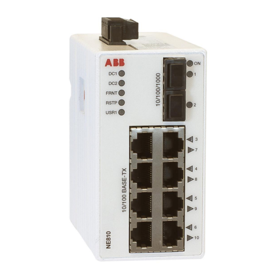
Section 3 Location of interface ports and LED‘s Figure 1. Location of interface ports and LED‘s 3BSE080633... -
Page 13: Connection To Console Port
The console port can be used to connect to the CLI (Command Line Interface). The following steps needs to be taken: 1. Connect the serial diagnostic cable to the console port (use only ABB cable 3BSE080212R1). 2. Connect cable to your computer (USB port, if drivers are needed they can be downloaded from our Web page). -
Page 14: I/O Connection
I/O Connection Figure 3. I/O Connection 4-position Product marking Direction Description No. 1 Status + Output Alarm relay (status) contact No. 2 Status – Output Alarm relay (status) contact No. 3 Digital in + Input Digital in + No. 4 Digital in –... - Page 15 Section 3 Location of interface ports and LED‘s The Status output is a potential free, opto-isolated normally closed solid-state relay. This can be configured to monitor various alarm events within the NE810 unit, see NEOS User Manual. An external load in series with an external voltage source is required for proper functionality.
-
Page 16: Led Indicators
LED Indicators Figure 5. LED Indicators 3BSE080633... - Page 17 Section 3 Location of interface ports and LED‘s Status Description Unit has no power GREEN All OK, no alarm condition Alarm condition, or until unit has started up. (Alarm conditions are configurable,see, NEOS User Manual) Location indicator “Here I am”. BLINK Activated when connected to IPConfig Tool, or upon request from Web or CLI...
-
Page 18: Mounting
This unit should be mounted on 35 mm DIN-rail, which is horizontally mounted inside an apparatus cabinet or similar. It is recommended that the DIN-rail is connected to ground. Snap on mounting, see Figure Figure 6. Mounting NE810 with integrated DIN-clip 3BSE080633... -
Page 19: Removal
Removal Press down the support at the back of the unit using a screwdriver. See Figure Figure 7. Removing NE810 with integrated DIN-clip Cooling This unit uses convection cooling. To avoid obstructing the airflow around the unit, use the following spacing rules. Minimum spacing 25 mm (1.0 inch) above / below and 10 mm (0.4 inches) left / right the unit. -
Page 20: Getting Started
Spacing is recommended for the use of unit in full operating temperature range and service life. Getting Started This product runs ABB Network Equipment Operating System (NEOS) which pro- vides several management tools that can be used for configuration of the unit. •... -
Page 21: Configuration
Section 3 Location of interface ports and LED‘s information, please use the CLI. Detailed documentation is available in the chapter The Command Line Management Tool in the NEOS User Manual. Factory default: – IP address: 172.16.5.245 – Netmask: 255.255.252.0 – Gateway: Disabled Consult your network administrator to know more on subnet. -
Page 22: Maintenance
Maintenance No maintenance is required, as long as the unit is used as intended within the specified conditions. Agency Approvals and Standards Compliance Type Approval / Compliance EN 61000-6-1, Immunity residential environments EN 61000-6-2, Immunity industrial environments EN 61000-6-4, Emission industrial environments EN 50121-4, Railway signalling and telecommunications apparatus IEC 62236-4, Railway signalling and telecommunications... -
Page 23: Notice: En 55022
Section 3 Location of interface ports and LED‘s Type Tests and Environmental Conditions Environmental Basic standard Description Test levels phenomena EN 61000-4-2 Enclosure Contact: ±6 kV Air: ±8 kV Fast transients EN 61000-4-4 Power port ±2 kV Signal ports ±2 kV Earth port ±1 kV Surge... - Page 24 Pulsed EN 61000-4-9 Enclosure 300 A/m magnetic field Radiated RF EN 61000-4-3 Enclosure 10 V/m @ (80 – 800) MHz immunity 20 V/m @ (800 – 1000) MHz 10 V/m @ (1400 – 2100) MHz 5 V/m @ (2100 – 2500) MHz 1 V/m @ (2500 –...
- Page 25 Section 3 Location of interface ports and LED‘s Altitude Operating 2 000 m / 70 kPa Service life Operating 10 years Reliability MIL-HDBK- 217F Operating 630 000 hours prediction (MTBF) Vibration IEC 60068-2-6 Operating 3 – 13.2 Hz: 1mm (sine) 13.2 –...
-
Page 26: Referring Documents
System 800xA 6.0 Network Guide Configuration Guide Cable Factory Reset on NE810 It is possible to set the unit to factory default settings by using two straight standard Ethernet RJ-45 cables. 1. Power off the switch and disconnect all Ethernet cables (copper and fibre). -
Page 27: Skip The Factory Reset
Section 3 Location of interface ports and LED‘s Skip the Factory Reset To skip the factory reset process, just wait for approximately 30 seconds (after the ON LED starts flashing RED) without unplugging the Ethernet cables. The switch will conduct a normal boot with the existing settings. Do not power off the unit while the factory reset process is in progress. - Page 28 Contact us Copyright© 2017 ABB. www.abb.com/800xA www.abb.com/controlsystems All rights reserved.