Advertisement
Quick Links
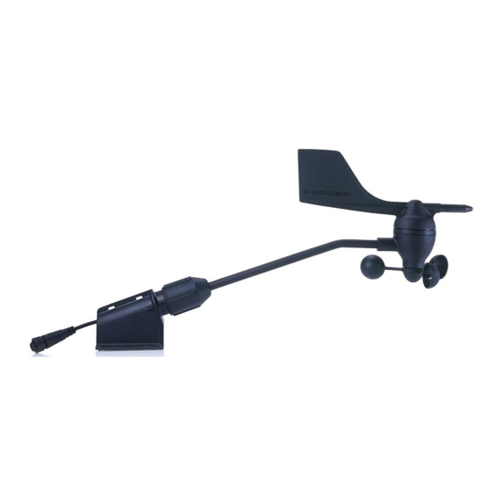
This manual provides the instructions for how to install the Wind Transducer FI-5001/FI-
5001L. For connection to the instrument, see the operator's manual of the instrument.
Basic Configuration
Wind Transducer
FI-5001/FI-5001L
Terminal Box
(where necessary)
Instrument
FI-501
OR
12 VDC
Package Contents
Name
Wind Transducer
Lock Fitting
Self-tapping Screw
Cable Tie
Cable Assy.
Terminal Box
Terminal Box Cover
Self-tapping Screw
Terminal Post
Cable Tie
All brand and product names are trademarks, registered trademarks or service marks of their respective holders.
Analog NMEA Data Converter
FI-502
Type
FI-5001
FI-5001L
FI-5001L-LOCK
4×20 SUS304
CV-150B
FI-50-SENSOR-30
FI-50-SENSOR-50
M03-9373
M03-9372
3×12 SUS304
4E/6
CV-100N
www.furuno.com
Installation Manual
WIND TRANSDUCER
FI-5001/FI-5001L
Model
Terminal Box
IF-NMEAFI
CAN bus (NMEA2000) backbone cable
12-15 VDC
Code No.
Qty
-
-
000-170-594-10
000-158-850-10
000-167-183-10
FI-5001: 3 pcs, FI-5001L: 2 pcs
000-166-946-10
000-166-947-10
000-167-986-10
000-167-985-10
000-167-824-10
000-168-024-10
000-162-167-10
Wind Transducer
FI-5001/FI-5001L
Instrument
FI-70
Remarks
Length: 370 mm
1
Length: 720 mm
1
4
1
Select one.
1
1
4
1
For Terminal Box
4
Advertisement

Related Manuals for Furuno FI-5001


Summary of Contents for Furuno FI-5001
- Page 1 Installation Manual WIND TRANSDUCER FI-5001/FI-5001L Model This manual provides the instructions for how to install the Wind Transducer FI-5001/FI- 5001L. For connection to the instrument, see the operator’s manual of the instrument. Basic Configuration Wind Transducer Wind Transducer FI-5001/FI-5001L FI-5001/FI-5001L...
- Page 2 Installation Site Fix the transducer to the mounting mast so that its mounting base is parallel with the water line. Also, position the transducer so its leading edge faces the bow. Mounting Procedure 1. Orient the mounting base as shown figure below, with the threaded part of the mount- ing base facing the bow.
- Page 3 For wiring with the terminal box, see the FI-501/FI-502 oper- ator’s manual. For FI-70: To use the FI-5001/L sensor data for the FI-70, it is required to convert the analog data to the CAN bus (NMEA2000) format data with the IF-NMEAFI. For details of wiring, see the FI-70 operator’s manual.
- Page 6 5. 手順 4 で取 り 付けたケーブル組品 FI-50-SENSOR-30/50 を固定具の上でループ を作 り 、 付属の束線バン ド (CV-150B、 2 本) を使 っ て固定具上部の穴 (2 ヵ 所) で留め ます。 6. FI-501/FI-502 と 接続する場合 : イ ン ス ツル メ ン ト 背面のポー ト に、 ケーブル組品 FI-50-SENSOR-30/50 の...
- Page 7 装備位置について 風向風速セ ンサーは、 固定具の取付け面が水平にな る よ う にマ ス ト 上に取 り 付けて く だ さ い。 ま た、 セ ンサーの先端が船首方向を向 く よ う に し て く だ さ い。 装備手順 1. 付属の タ ッ ピ ン ネジ (φ4×20、 4 本) を使 っ て、 マ ス ト の上に固定具を取 り 付け ます。...
- Page 8 装備要領書 風向風速セ ンサー FI-5001/FI-5001L 型式 本書は、 風向風速セ ンサー FI-5001/FI-5001L の装備方法について記載 し てい ます。 結 線方法については、 イ ン ス ツル メ ン ト (表示部) の取扱説明書を参照 し て く だ さ い。 基本構成 同梱物 名称 型式 部品コード 数量 備考 FI-5001 長 さ : 370mm 風向風速セ...