Table of Contents
Advertisement
This owner's manual applies to the ERTIGA GLX
produced by SUZUKI (MYANMAR) MOTOR CO., LTD.
SUZUKI (MYANMAR) MOTOR CO., LTD.
SUZUKI (MYANMAR) MOTOR CO., LTD.
Copyright ©
No part of this document may be reproduced or transmitted in any form or by any means, electronic or
mechanical, for any purpose, without the express written permission of SUZUKI (MYANMAR) MOTOR CO., LTD.
NOTE: The illustrated model is one of the ERTIGA series.
2016 All Rights Reserved
60MK183
60MK1-82E
Advertisement
Chapters
Table of Contents

Related Manuals for Suzuki Ertiga Series


Summary of Contents for Suzuki Ertiga Series
- Page 1 Copyright © 2016 All Rights Reserved No part of this document may be reproduced or transmitted in any form or by any means, electronic or mechanical, for any purpose, without the express written permission of SUZUKI (MYANMAR) MOTOR CO., LTD. 60MK1-82E...
- Page 2 Please read this manual carefully cial information, the symbol and the tion in this manual and your vehicle. before operating your new SUZUKI and words WARNING, CAUTION, NOTICE SUZUKI (MYANMAR) MOTOR CO., LTD. review the manual from time to time. It and NOTE have special meanings.
- Page 3 CB (Citizen’s Band) radios may cause electronic interfer- ence with your vehicle’s ignition sys- tem, resulting in vehicle performance problems. Consult your SUZUKI dealer or qualified service technician for advice on installing such mobile communication equipment. 60MK1-82E...
- Page 4 INTRODUCTION Thank you for choosing SUZUKI and welcome to our growing family. Your choice was a wise one; SUZUKI products are a great value that will give you years of driving pleasure. This Owner’s Manual was prepared to help you have a safe, enjoyable, and trouble-free experience with your SUZUKI. In it you will learn about the vehicle’s operation, its safety features and maintenance requirements.
- Page 5 A wide variety of non-genuine replacement parts and accessories for SUZUKI vehicles are currently available in the market. Using these parts and accessories can affect the vehicle performance and shorten its useful life. Therefore, installation of non-genuine SUZUKI parts and accessories is not covered under warranty.
- Page 6 Authorized Suzuki dealers will be pleased to help you with Suzuki service. With their expertise and experience, Suzuki dealers can offer you the best service to ensure a safe and comfortable driving experience.
- Page 7 SERVICE STATION GUIDE 1. Fuel (see section 1) 2. Engine hood (see section 5) 3. Tire changing tools (see section 8) 4. Engine oil dipstick <Yellow> (see section 7) 5. Automatic transaxle fluid dipstick <Red> (see section 7) 6. Engine coolant (see section 7) 7.
-
Page 8: Table Of Contents
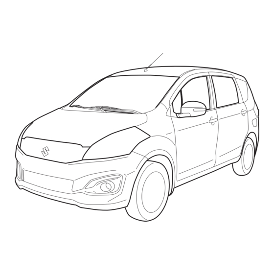
TABLE OF CONTENTS FUEL RECOMMENDATION BEFORE DRIVING OPERATING YOUR VEHICLE DRIVING TIPS OTHER CONTROLS AND EQUIPMENT VEHICLE LOADING AND TOWING INSPECTION AND MAINTENANCE EMERGENCY SERVICE APPEARANCE CARE GENERAL INFORMATION SPECIFICATIONS INDEX 60MK1-82E... - Page 9 ILLUSTRATED TABLE OF CONTENTS EXTERIOR 1. Rear Window Wiper (P.2-63) 2. High-mount Stop Light (P.7-28) 3. Radio Antenna (P.5-7) 4. Engine Hood (P.5-10) 5. Headlight (P.2-59, 7-25) 6. Windshield Wiper (P.2-62) 7. Fuel Filler Cap (P.5-9) 8. Parking Sensor (P.3-15) 9.
- Page 10 ILLUSTRATED TABLE OF CONTENTS INTERIOR 1. Interior Light (P.5-12, 7-24) 5. Electric Mirrors Control Switch (P.2-17)/ 9. Parking Brake Lever (P.3-8) 2. Seat Belts (P.2-25) Electric Window Controls (P.2-15) 10. Front Seats (P.2-18) 3. Assist Grips (P.5-14) 6. Sun Visor (P.5-11) 11.
- Page 11 ILLUSTRATED TABLE OF CONTENTS INSTRUMENT PANEL 1. Lighting Control Lever (P.2-59)/ Turn Signal Control Lever (P.2-60) 2. Front Air Bags (P.2-38) 3. Instrument Cluster (P.2-43) 4. Windshield Wiper and Washer Lever (P.2-62)/Rear Window Wiper and Washer Switch (P.2-63) 5. Audio (if equipped) (P.5-8) 6.
-
Page 12: Fuel Recommendation
FUEL RECOMMENDATION FUEL RECOMMENDATION Fuel Recommendation ............1-1 65D394 60MK1-82E... - Page 13 Note, it is preferable to use unleaded gas- spilled on the vehicle body, wipe it up the responsibility of SUZUKI and may not oline. immediately. Fuels containing alco- be covered under the New Vehicle War- hol can cause paint damage, which is ranty.
-
Page 14: Before Driving
BEFORE DRIVING BEFORE DRIVING Keys ..................2-1 Door Locks ................2-3 Keyless Push Start System Remote Controller ....2-6 Theft Deterrent Alarm System ........... 2-12 Windows ................2-15 Mirrors .................. 2-17 Front Seats ................2-18 Rear Seats ................2-20 Seat Belts and Child Restraint Systems ......2-25 Supplemental Restraint System (air bags) ....... -
Page 15: Keys
BEFORE DRIVING Keys To remove the key from the remote control- ler, slide the lock (3) in the direction of the arrow and pull out the key. 57L21003 60MK152 The key identification number (4) is Your vehicle comes with two identical key- stamped on a metal tag (5) provided with 57L21016 less push start system remote controllers... - Page 16 • If you lose your remote controller, see This immobilizer system, model 37290- SUZUKI dealer. The vehicle must be pro- your SUZUKI dealer as soon as possible 79M0 is in compliance with the essential...
-
Page 17: Door Locks
BEFORE DRIVING Door Locks Central Door Locking System EXAMPLE Side Door Locks EXAMPLE 60MK103 EXAMPLE (1) LOCK 60MK144 (2) UNLOCK (1) UNLOCK 60MK143 (2) LOCK (1) UNLOCK To lock a door from inside the vehicle, turn (3) Front (2) LOCK the lock knob forward. - Page 18 BEFORE DRIVING NOTE: NOTE: Child-Proof Locks (rear door) You can switch the function that unlocks all You can also lock or unlock all doors by doors from twice operations to once opera- operating the remote controller or pushing tion, and vice versa, via the setting mode the request switch.
- Page 19 (1) due to a dis- ing up the tailgate handle (1), have the charged battery or malfunction, follow the vehicle inspected by your SUZUKI dealer. procedures below to unlatch the tailgate from inside the vehicle. CAUTION 1) Fold the 3rd row seat forward for easier •...
-
Page 20: Keyless Push Start System Remote Controller
• If the interior light switch is in the SUZUKI dealer. “DOOR” position, the interior light will turn on for about 15 seconds and then fade out. If you press the engine switch during this time, the light will start to fade 68LM206 out immediately. - Page 21 • If you lose one of the remote controllers, the request switch under the following the doors are locked. ask your SUZUKI dealer as soon as pos- conditions: sible for a replacement. Be sure to have – If any door is open or is not completely your dealer program the new remote closed.
- Page 22 BEFORE DRIVING • If no doors are opened within about 30 NOTE: NOTICE seconds after unlocking the doors by • If the remote controller is outside the pushing the request switch, the doors request switch operating range The remote controller is a sensitive will be locked again automatically.
- Page 23 • If you lose one of the remote controllers, With the ignition mode changed to “LOCK” ask your SUZUKI dealer as soon as pos- (OFF) by pressing the engine switch, bring sible for a replacement. Be sure to have...
- Page 24 BEFORE DRIVING The indicator light will turn off within sev- Replacement of the battery eral seconds after the remote controller is If the remote controller becomes unreli- returned to interior workable area. able, replace the battery. If the remote controller is left in the vehicle To replace the battery of the remote con- and you lock the driver’s door or front pas- troller:...
- Page 25 The recy- cling of materials will help to conserve natural resources. For more detailed infor- mation about disposing or recycling of the used battery, consult your SUZUKI dealer. 2-11 60MK1-82E...
-
Page 26: Theft Deterrent Alarm System
BEFORE DRIVING Theft Deterrent Alarm System NOTE: How to arm the theft deterrent alarm • The theft deterrent alarm system gener- system (when enabled) The theft deterrent alarm system is armed ates alarms when any of the predeter- Lock the doors using the keyless push in about 20 seconds after you lock the mined conditions is met. - Page 27 BEFORE DRIVING NOTE: How to stop the alarm Checking whether the alarm has been • To prevent the alarm from being acci- Should the alarm be triggered accidentally, triggered during parking dentally triggered, avoid arming it while unlock the doors using the keyless push If the alarm was triggered due to an unau- anyone remains inside the vehicle.
- Page 28 BEFORE DRIVING How to switch the state of the theft 1) With the ignition mode “ON”, close all deterrent alarm system the doors and turn the lock knob (1) on EXAMPLE You can switch the theft deterrent alarm the driver’s door in the unlocking direc- system from the enabled state to the dis- tion (2) (rearward).
-
Page 29: Windows
BEFORE DRIVING Windows Every time you perform the series of the Passenger’s door above steps, the state of the theft deterrent EXAMPLE Electric Window Controls alarm system changes from the currently selected one to the other. You can check The electric windows can only be operated whether the system is enabled or disabled when the ignition mode is “ON”. - Page 30 BEFORE DRIVING Lock switch WARNING EXAMPLE CLOSE • You should always lock the pas- senger’s window operation when there are children in the vehicle. Children can be seriously injured if they get part of their body caught by the window during operation. •...
-
Page 31: Mirrors
BEFORE DRIVING Mirrors To adjust the mirror, set the selector tab (1) Outside Rearview Mirrors to the day position, then move the mirror Adjust the outside rearview mirrors so you Inside Rearview Mirror up, down or sideways by hand to obtain can just see the side of your vehicle in the You can adjust the inside rearview mirror the best view. -
Page 32: Front Seats
BEFORE DRIVING Front Seats 2) Press the outer part of the switch that Outside Rearview Mirrors Folding corresponds to the direction in which Switch Seat Adjustment you wish to move the mirror. 3) Return the selector switch to the center EXAMPLE position to help prevent unintended WARNING... - Page 33 BEFORE DRIVING Adjusting Seat Position Adjusting Seatbacks WARNING All seatbacks should always be in an upright position when driving, or seat belt effectiveness may be reduced. Seat belts are designed to offer maxi- mum protection when seatbacks are in the upright position. EXAMPLE EXAMPLE 60MK158...
-
Page 34: Rear Seats
BEFORE DRIVING Rear Seats Head Restraints Front EXAMPLE Seat Adjustment WARNING To avoid excessive seat belt slack, which reduces the effectiveness of the seat belts as a safety device, make sure that the seats are adjusted before the seat belts are fastened. 80JS082 80J001 To raise the front head restraint, pull... - Page 35 BEFORE DRIVING Adjusting Seat Position Adjusting Seatbacks Walk-in Type Seats (for 2nd row seats) (for 2nd row seats) WARNING All seatbacks should always be in an upright position when driving, or seat belt effectiveness may be reduced. Seat belts are designed to offer maxi- mum protection when seatbacks are in the upright position.
- Page 36 BEFORE DRIVING Head Restraints 2nd row seats Head restraints are designed to help EXAMPLE reduce the risk of neck injuries in the case of an accident. WARNING • Never drive the vehicle with the head restraints removed. • Do not attempt to adjust the head restraint while driving.
- Page 37 BEFORE DRIVING To raise the rear head restraint, pull Folding Rear Seats 2) Lower the head restraint fully. upward on the restraint until it clicks. To The rear seat of your vehicle can be folded 3) Store the seat belt buckles in the seat lower the restraint, push down on the forward to provide additional cargo space.
- Page 38 BEFORE DRIVING To return the seat to the normal position, 3rd row seats NOTICE follow the procedure below. To fold the 3rd row seats forward: When the 3rd row seat head restraint 1) Lower the head restraint fully. EXAMPLE reaches the 2nd row seatback, slide 2) Store the seat belt buckles in the seat the 2nd row seat forward.
-
Page 39: Seat Belts And Child Restraint Systems
BEFORE DRIVING Seat Belts and Child Restraint To return the seat to the normal position, follow the procedure below. Systems EXAMPLE Above the pelvis 65D606 60MK160 WARNING 65D231S Raise the seatback until it locks into place. • Never allow persons to ride in the cargo area of a vehicle. - Page 40 BEFORE DRIVING WARNING (Continued) • Never use the same seat belt on more than one occupant and never attach a seat belt over an infant or as low as possible child being held on an occupant’s across the hips Across the pelvis lap.
- Page 41 BEFORE DRIVING Lap-Shoulder Belt WARNING Emergency Locking Retractor (ELR) (Continued) The seat belt has an emergency locking Low on hips • For children, if the shoulder belt retractor (ELR), which is designed to lock irritates the neck or face, move the the seat belt only during a sudden stop or child closer to the center of the impact.
- Page 42 BEFORE DRIVING All Seat Belts Except Center of 2nd Center Seat Belt of 2nd Row Seat Row Seat Lap belt TO TIGHTEN Low on hips 60A039 To unfasten the seat belt, push the button 60A036 on the buckle and retract the belt slowly 60MH021 To fasten the seat belt, sit up straight and while attaching a hand to the belt or/and...
- Page 43 BEFORE DRIVING Driver’s Seat Belt Reminder TO LOOSEN EXAMPLE EXAMPLE 60MH022 80J2008 To lengthen, release the latch plate from NOTE: 60MK190 the buckle, pull the latch plate (adjuster) in The word “CENTER” is marked into the the direction of the arrow. The latch plate buckle for the rear center belt.
- Page 44 BEFORE DRIVING When the driver does not buckle his or her Shoulder Anchor Height Adjuster Seat Belt Hanger (for 2nd row seats) seat belt with the ignition mode “ON”, the (if equipped) EXAMPLE driver’s seat belt reminder light in the EXAMPLE instrument cluster will blink until the driver’s seat belt is buckled.
- Page 45 BEFORE DRIVING Seat Belt Inspection Child Restraint Systems WARNING EXAMPLE Be sure to inspect all seat belt assemblies after any collision. Any seat belt assembly which was in use during a collision (other than a very minor one) should be replaced, even if damage to the assembly is not obvious.
- Page 46 BEFORE DRIVING Child restraint SUZUKI highly recommends that you use a child restraint system to restrain infants EXAMPLE and small children. Many different types of child restraint systems are available; make sure that the restraint system you select meets applicable safety standards.
- Page 47 BEFORE DRIVING WARNING WARNING If you install a child restraint system Children could be endangered in a in the 2nd row seat, slide the seat crash if their child restraint systems installed the child restraint system as are not properly secured in the vehi- far back as possible.
- Page 48 Install your child restraint system accord- ing to the instructions provided by the child WARNING restraint system manufacturer. This section of the owner’s manual describes your SUZUKI’s SEAT BELT To lengthen or tighten the belt, refer to the PRETENSIONER SYSTEM. Please “Lap-belt”...
- Page 49 Read this section and the “Supplemental not indicate a fire in the vehicle. rized SUZUKI dealer as soon as possible. Restraint System (air bags)” section to The driver and all passengers must be If the “AIR BAG” light on the instrument learn more about the pretensioner system.
- Page 50 Do not touch pretensioner system compo- nents or wiring. The wires are wrapped with yellow tape or yellow tubing, and the couplers are yellow. When scrapping your SUZUKI, ask your SUZUKI dealer, body repair shop, or scrap yard for assistance. 2-36 60MK1-82E...
-
Page 51: Supplemental Restraint System (Air Bags)
System (air bags) WARNING This section of the owner’s manual describes the protection provided by your SUZUKI’s SUPPLEMENTAL RESTRAINT SYSTEM (air bags). Please read and follow ALL these instructions carefully to minimize your risk of severe injury or death in the event of a collision. - Page 52 Have the air bag system 60MK114 80JS026 inspected by an authorized SUZUKI dealer The driver’s front air bag is located behind Driver’s front air bag as soon as possible. the center pad of the steering wheel and EXAMPLE the front passenger’s front air bag is...
- Page 53 BEFORE DRIVING Frontal collision range Front air bags will not inflate dents. Remember, since an air bag deploys only one time during an accident, seat belts are needed to restrain occu- pants from further movements during the accident. Therefore, an air bag is NOT a substitute for seat belts.
- Page 54 BEFORE DRIVING Air bag symbol meaning WARNING EXAMPLE If the AIR BAG light in the instrument cluster ever comes on and stays on, WARNING AVERTISSEMENT it means that something may be ADVERTENCIA WARNUNG wrong with the air bag system. If this ATTENZIONE WAARSCHUWING VIGYÁZAT...
- Page 55 BEFORE DRIVING How the System Works A seat belt helps keep you in the proper WARNING In a frontal collision, the crash sensors will position for maximum protection when an detect rapid deceleration, and if the con- air bag inflates. Adjust your seat as far •...
- Page 56 If your vehicle ever gets in deep water and authorized SUZUKI dealer to ensure it is in the driver’s floor is submerged, the air bag proper working order. controller could be damaged. If it does,...
-
Page 57: Instrument Cluster
BEFORE DRIVING Instrument Cluster 1. Speedometer 4. Temperature gauge 7. Indicator selector knob 2. Tachometer 5. Information display 8. Warning and indicator lights 3. Fuel gauge 6. Trip meter selector knob EXAMPLE 60MK191 * These marks are explanation of the knobs 6 and 7. Refer to “Brightness Control” or “Information Display” in this section for detail of knobs. -
Page 58: Warning And Indicator Lights
If any of the following conditions the vehicle’s brake system. If this happens, occur, you should immediately ask you should: your SUZUKI dealer to inspect the 1) Pull off the road and stop carefully. brake system. • If the brake system warning light... - Page 59 If this happens: If there is enough oil, the lubrication sys- 1) Pull off the road and stop carefully. tem should be inspected by your SUZUKI 2) Change the ignition mode to “LOCK” dealer before you drive the vehicle again.
- Page 60 “ON”, stays on for more Bring the vehicle to your SUZUKI dealer to than 10 seconds, or comes on while have the damage fixed. driving, the air bag system or the...
- Page 61 This light remains on until all doors (includ- running, there is the problem with the auto- ing the tailgate) are completely closed. matic transaxle system. Ask your SUZUKI dealer to have the system inspected. If any door (including the tailgate) is open when the vehicle is moving, a ding sounds to remind you to close all doors completely.
- Page 62 Have the system inspected by your SUZUKI dealer. Main Beam (high beam) Indicator Light NOTE: Following operations of the steering wheel...
-
Page 63: Speedometer
BEFORE DRIVING Speedometer Keyless Push Start System Remote “ACC” Indicator Light Controller Battery Consumption Warning Light EXAMPLE 82K097 This light comes on when the ignition mode is “ACC”. 70K122 If the remote controller becomes unreli- Ignition “ON” Indicator Light able, this light comes on for several sec- onds when the engine switch is pressed to change the ignition mode to “ON”. -
Page 64: Tachometer
BEFORE DRIVING Tachometer Fuel Gauge When the low fuel warning light (1) comes on, a ding sounds once to remind you to fill the fuel. EXAMPLE If you do not fill the fuel, a ding sounds every time when the engine switch is pressed to change the ignition mode to “ON”. -
Page 65: Temperature Gauge
BEFORE DRIVING Temperature Gauge Brightness Control EXAMPLE (Brightest) (Initial setting) EXAMPLE EXAMPLE 74LHT0221 60MK180 (Dimmest) When the ignition mode is “ON”, this When the engine switch is pressed to gauge indicates the engine coolant tem- change the ignition mode to “ON”, the 60MH025 perature. -
Page 66: Information Display
BEFORE DRIVING Information Display NOTE: When the ignition mode is “ON”, the infor- • If you do not turn the brightness control mation display shows the following infor- knob within several seconds of activat- mation. EXAMPLE ing the brightness control display, the Display (A) brightness control display will be can- Thermometer... - Page 67 BEFORE DRIVING Thermometer When the display (C) shows the driving Transaxle selector position indicator When the ignition mode is “ON”, the dis- range, you can change the unit of tem- play (A) shows the thermometer. perature. EXAMPLE ( b) The thermometer indicates the outside To change the unit of temperature, while pushing and holding the trip meter selector temperature.
- Page 68 BEFORE DRIVING Trip meter Push the trip meter selector The trip meter can be used to measure the EXAMPLE knob (1). distance traveled on short trips or between fuel stops. Push the indicator selector You can use the trip meter A or trip meter B knob (2).
- Page 69 BEFORE DRIVING Instantaneous Fuel Consumption Average fuel consumption To change the unit of average fuel con- The display shows the value of instanta- If you selected average fuel consumption sumption, while pushing and holding the neous fuel consumption only when the the last time you drove the vehicle, the dis- trip meter selector knob (1), turn the indica- vehicle is moving.
- Page 70 BEFORE DRIVING Driving range Odometer To change the time indication: If you selected driving range the last time When the ignition mode is “ON”, the dis- 1) Push the trip meter selector knob (1) you drove the vehicle, the display indicates play (D) shows the odometer.
- Page 71 BEFORE DRIVING Setting Mode In the setting mode, you can set up the following functions. Indication Functions Central door locking system “ ” Door locking and unlocking buzzer “ ” Additional flashes of the turn signal “ ” Security system “ ”...
- Page 72 BEFORE DRIVING How to operate the setting mode: Door locking and unlocking Initialization setting “ ” 1) When the ignition mode is “ON” and the buzzer “ ” • Initialize all settings vehicle is stationary, push the trip meter • : Buzzer sounds when...
-
Page 73: Lighting Control Lever
BEFORE DRIVING Lighting Control Lever Lighting Operation EXAMPLE EXAMPLE 60MK117 60MK116 With the headlights on, push the lever for- 60MK115 ward to switch to the high beams (main To turn the lights on or off, twist the knob beams) or pull the lever toward you to on the end of the lever. -
Page 74: Front Fog Light Switch
BEFORE DRIVING Front Fog Light Switch Turn Signal Control Lever Light Reminder Buzzer A buzzer sounds to remind you to turn off the lights if they are left on when the engine switch is pressed to change the ignition mode to “LOCK” (OFF) and the driver’s door is opened. -
Page 75: Hazard Warning Switch
NOTE: You can customize the setting for the num- ber of times of flashing of the turn signal and its indicator (1 to 4 times). Please ask an authorized SUZUKI dealer for the cus- tomization. 2-61 60MK1-82E... -
Page 76: Windshield Wiper And Washer Lever
BEFORE DRIVING Windshield Wiper and Washer Wiper and Washer Operation Windshield Washer When the ignition mode is “ON”, you can Lever use the wiper/washer lever or switch. Windshield Wipers EXAMPLE 60MK200 To spray windshield washer fluid, pull the lever toward you. The windshield wipers 60MK119 EXAMPLE will automatically turn on at low speed if... - Page 77 BEFORE DRIVING Rear Window Wiper/Washer Switch NOTICE NOTICE EXAMPLE To help prevent damage to the wind- Clear ice or snow from the rear win- Washer shield wiper and washer system dow and rear wiper blade before components, you should take the fol- using the rear wiper.
-
Page 78: Tilt Steering Lock Lever
BEFORE DRIVING Tilt Steering Lock Lever Horn WARNING EXAMPLE Never attempt to adjust the steering EXAMPLE wheel while the vehicle is moving or you could lose control of the vehicle. 60MK123 68LM240 (1) LOCK Press the horn button of the steering wheel (2) UNLOCK to sound the horn. -
Page 79: Heated Rear Window Switch
BEFORE DRIVING Heated Rear Window Switch NOTE: • The defogger will work only when the engine is running. EXAMPLE • The defogger will automatically turn off after the defogger remains on for 15 min- utes to prevent discharging of the bat- tery. -
Page 80: Operating Your Vehicle
OPERATING YOUR VEHICLE OPERATING YOUR VEHICLE Exhaust Gas Warning ............3-1 Daily Inspection Checklist ..........3-1 Engine Oil Consumption ............ 3-2 Engine Switch ..............3-3 Keyless Push Start System ..........3-4 Parking Brake Lever ............3-8 Pedal ..................3-9 Starting the Engine ............. 3-10 Using the Transaxle ............ -
Page 81: Exhaust Gas Warning
OPERATING YOUR VEHICLE Exhaust Gas Warning Daily Inspection Checklist WARNING Before Driving (Continued) • Do not park with the engine run- ning for a long period of time, even in an open area. If it is necessary to sit for a short time in a parked vehi- cle with the engine running, make sure the air intake selector is set to “FRESH AIR”... -
Page 82: Engine Oil Consumption
OPERATING YOUR VEHICLE Engine Oil Consumption 4) Make sure the hood is fully closed and “CHASSIS AND BODY” in the “Periodic latched. Maintenance Schedule” It is normal for the engine to consume 5) Check the headlights, turn signal lights, “INSPECTION AND MAINTENANCE” some engine oil during normal vehicle brake lights and horn for proper opera- section for lubrication schedule. -
Page 83: Engine Switch
OPERATING YOUR VEHICLE Engine Switch making it appear that the oil level has not changed. • With the engine off You should also be aware that the diluting You can use such electric equipment as EXAMPLE ingredients evaporate out when the vehicle the power windows and wipers with the is subsequently driven at high speeds, engine off. -
Page 84: Keyless Push Start System
OPERATING YOUR VEHICLE Keyless Push Start System Engine Switch Illumination NOTICE The engine switch is illuminated (lit) in the Provided the keyless push start system following situations: remote controller is within the “interior Do not leave the engine switch in the •... - Page 85 OPERATING YOUR VEHICLE Selection of Ignition Modes Every time you press the engine switch, Press the engine switch to select the the ignition mode changes as follows. “ACC” or “ON” mode as follows when you use an electric accessory or check the operation of instruments without running Gearshift the engine.
- Page 86 When the conditions described below are the keyless push start system. Contact met, the system gives a “remote controller an authorized SUZUKI dealer for an outside” warning by sounding the interior inspection of the system. and exterior buzzers and blinking the •...
- Page 87 OPERATING YOUR VEHICLE • Always keep the remote controller with NOTE: you as the driver. • Even when the remote controller is in the “interior workable area”, if it is in any of Interior Workable Area for Engine the following conditions, you may not be able to start the engine or select the igni- Starting, Ignition Mode Selection tion modes, and the “remote controller...
-
Page 88: Parking Brake Lever
To release the you must remember to first set the rized SUZUKI dealer. parking brake, hold the brake pedal down, parking brake, then remove the pull up slightly on the parking brake lever, wheel chocks. -
Page 89: Pedal
Pedal Parking Brake Reminder Buzzer Brake Pedal (1) A buzzer sounds intermittently to remind Your SUZUKI vehicle is equipped with front you to release the parking brake if you disc brakes and rear drum brakes. EXAMPLE start the vehicle without releasing the park- Depressing the brake pedal applies both ing brake. -
Page 90: Starting The Engine
OPERATING YOUR VEHICLE Starting the Engine NOTICE Before Starting the Engine • Do not depress the accelerator during the engine starting proce- dure. • If the engine does not respond when you try to start it with the engine switch or if the engine switch repeats cycling through the “LOCK”(OFF) - “ACC”... - Page 91 If you are unable to start the engine using (Park) position, shift it to “P”. Hold the before stopped, a clicking sound may be this procedure, consult your SUZUKI brake pedal fully depressed. heard from around the engine when dealer.
- Page 92 “PUSH” indicator light this happens, have the vehicle inspected Whenever you leave the vehicle, make is blinking. by an authorized SUZUKI dealer after sure you have returned the ignition mode • You may customize the system to cause doing the following: to “LOCK”...
-
Page 93: Using The Transaxle
OPERATING YOUR VEHICLE Using the Transaxle Overdrive off switch Gearshift lever The transaxle is a 4-speed (3-speed plus EXAMPLE 4-Speed Automatic Transaxle overdrive) automatic transaxle. By operat- ing the overdrive off switch, the transaxle can be converted to a 3-speed automatic EXAMPLE transaxle that will not move to the over- drive position. - Page 94 OPERATING YOUR VEHICLE The gearshift lever has a lock mechanism Use the gearshift lever positions as L (Low 1) to help prevent accidental shifting. To shift described below: Use this position to provide maximum the gearshift lever: power when climbing steep hills or driving P (Park) through deep snow or mud, or to provide Use this position to lock the transaxle...
-
Page 95: Parking Sensors
OPERATING YOUR VEHICLE Parking Sensors If You Cannot Shift Automatic Transaxle 5) With pushing the release button by the Gearshift Lever Out of “P” (PARK) key or the flat end rod, push the knob • The parking sensor system uses ultra- button (2) and shift the gearshift lever to sonic sensors to detect obstacles near the desired position. - Page 96 If this occurs, have the sen- from a sensor or just below a sensor is sors inspected by an authorized not detectable. SUZUKI dealer. • The sensors can detect an obstacle up to about 1.5 m (5 ft) from the rear of vehicle.
- Page 97 OPERATING YOUR VEHICLE NOTE: WARNING WARNING • Thin poles or obstacles lower than the sensors may become undetectable as • Under the following conditions, the (Continued) the vehicle moves closer to them even if parking sensor system may not – Sensors have intercepted ultra- they have been detected from longer work normally because the sensors sonic noise from another vehi-...
- Page 98 OPERATING YOUR VEHICLE • When the ignition mode is “ON”, and the indicator light in the parking sensor switch is Obstacle Indication by Parking Sen- on, indicating that the parking sensor is ready for operation under the following condi- tions: Upon detecting an obstacle, the parking –...
-
Page 99: Braking
Have your vehicle The distance needed to bring any vehicle Your vehicle has power-assisted brakes. If inspected by an authorized SUZUKI to a halt increases with the speed of the power assistance is lost due to a stalled dealer. - Page 100 OPERATING YOUR VEHICLE WARNING WARNING WARNING Even without reserve power in the • On some types of loose surfaces (Continued) brake system, you can still stop the (such as gravel, snow-covered • In both of the above conditions, vehicle by pressing the brake pedal roads, etc.) the stopping distance ABS will still offer the advantage of harder than normally required.
- Page 101 ABS system. change braking pressure several times Ask your SUZUKI dealer to inspect each second to prevent the wheels from the ABS system immediately. If the locking. When you start your vehicle or...
-
Page 102: Driving Tips
DRIVING TIPS DRIVING TIPS Running-in ................4-1 Catalytic Converter ............. 4-1 Improving Fuel Economy ........... 4-2 Highway Driving ..............4-3 Driving on Hills ..............4-3 Driving on Slippery Roads ..........4-4 60G409 60MK1-82E... -
Page 103: Running-In
DRIVING TIPS Running-in Catalytic Converter NOTICE EXAMPLE The future performance and reliabil- ity of the engine depends on the care and restraint exercised during its early life. It is especially important to 52D078S observe the following precautions during the initial 960 km (600 miles) WARNING of vehicle operation. -
Page 104: Improving Fuel Economy
DRIVING TIPS Improving Fuel Economy NOTICE The following instructions will help you improve fuel economy. To avoid damaging catalyst or other vehicle damage: Avoid excessive idling • Maintain the engine in the proper If you are to wait for more than a minute operating condition. -
Page 105: Highway Driving
DRIVING TIPS Highway Driving Driving on Hills Keep the air cleaner clean When driving at highway speeds, pay EXAMPLE attention to the following: • Stopping distance progressively increases with vehicle speed. Apply the brakes far enough ahead of the stopping point to allow for the extra stopping dis- tance. -
Page 106: Driving On Slippery Roads
DRIVING TIPS Driving on Slippery Roads Tire Chains WARNING Tire chains should only be used if they are needed to increase traction or are required Try not to hold the brake pedal down by law. Make sure that the chains you use too long or too often while going are the correct size for your vehicle’s tires. - Page 107 1) Shift the transaxle back and forth • Do not use tires other than those between a forward range and reverse. specified by SUZUKI. Never use dif- This will create a rocking motion which ferent sizes or types of tires on the may give you enough momentum to front and rear wheels.
-
Page 108: Other Controls And Equipment
OTHER CONTROLS AND EQUIPMENT OTHER CONTROLS AND EQUIPMENT Manual Heating and Air Conditioning System ....5-1 Radio Antenna ..............5-7 Audio System (if equipped) ..........5-8 Fuel Filler Cap ..............5-9 Engine Hood ................ 5-10 Sun Visor ................5-11 Interior Light Switch ............5-12 Accessory Socket ............... -
Page 109: Manual Heating And Air Conditioning System
OTHER CONTROLS AND EQUIPMENT Manual Heating and Air Air Outlet Conditioning System EXAMPLE 60MK127 1. Windshield defroster outlet 2. Side defroster outlet 3. Side outlet 4. Center outlet 5. Floor outlet 60MK1-82E... - Page 110 OTHER CONTROLS AND EQUIPMENT Side outlet Center outlet 68LM502 74LHT0502 Move the knob (1) vertically and the dial Move the knob (1) vertically or horizontally to adjust the direction of airflow as desired. (2) horizontally, to adjust the direction of CAUTION airflow as desired.
- Page 111 OTHER CONTROLS AND EQUIPMENT Overhead rear air conditioning system Description of Controls Air flow selector (3) EXAMPLE 60MH028 63J048 60MH065 To turn on the overhead rear air condition- This is used to select one of the functions Temperature selector (1) ing system, set the blower speed selector This is used to select the temperature by described below.
- Page 112 OTHER CONTROLS AND EQUIPMENT Bi-level (b) Heat & defrost (d) Air intake selector (4) EXAMPLE EXAMPLE 60MK129 60MK131 68LM511 Temperature-controlled air comes out of Temperature-controlled air comes out of This selector is used to select the following the floor outlets and cooler air comes out the floor outlets, the windshield defroster modes.
- Page 113 OTHER CONTROLS AND EQUIPMENT Air conditioning switch (5) System Operating Instructions Head cooled/Feet warmed heating To turn on the air conditioning system, set Select “BI-LEVEL” and “FRESH AIR”, the Natural ventilation the blower speed selector to a position temperature selector to the desired tem- Select “VENTILATION”...
- Page 114 60MK133 “INSPECTION AND MAINTENANCE” sec- flow selector position, the temperature NOTE: tion. Have this job done by your SUZUKI selector to the desired temperature posi- If you need maximum defrosting: dealer as the lower glove box must be low- tion and the blower speed selector to the •...
-
Page 115: Radio Antenna
OTHER CONTROLS AND EQUIPMENT Radio Antenna EXAMPLE 68KH052 The radio antenna on the roof is remov- able. To remove the antenna, turn it coun- terclockwise. To reinstall the antenna, turn it clockwise firmly by hand. NOTICE avoid damage radio antenna: •... -
Page 116: Audio System (If Equipped)
OTHER CONTROLS AND EQUIPMENT Audio System (if equipped) AM/FM CD DVD PLAYER 60MK1-82E... -
Page 117: Fuel Filler Cap
OTHER CONTROLS AND EQUIPMENT Fuel Filler Cap The fuel filler cap is located on the left rear side of the vehicle. The fuel filler door can EXAMPLE be unlocked by pulling up the opener lever EXAMPLE located on the outboard side of the driver’s seat and locked by simply closing the door. -
Page 118: Engine Hood
Engine Hood WARNING If you need to replace the fuel cap, EXAMPLE use a genuine SUZUKI cap. Use of an improper cap can result in a malfunc- tion of the fuel system or emission control system. It may also result in fuel leakage in the event of an acci- dent. -
Page 119: Sun Visor
OTHER CONTROLS AND EQUIPMENT Sun Visor 3) Continue to lift up the hood until it is high enough to support with the prop EXAMPLE rod. EXAMPLE To close the engine hood: 1) Lift the hood up slightly and remove the prop rod from the hole. -
Page 120: Interior Light Switch
OTHER CONTROLS AND EQUIPMENT Interior Light Switch Card holder Vanity mirror EXAMPLE EXAMPLE Front EXAMPLE 60MK171 60MK172 (1) Card holder (2) Vanity mirror 60MH129 WARNING You can put a card in the card holder (1) on Rear the back of the sun visor. EXAMPLE When using the vanity mirror, do not move too close to a front air bag... -
Page 121: Accessory Socket
OTHER CONTROLS AND EQUIPMENT Accessory Socket This light switch has three positions which function as described below: EXAMPLE Front ON (1) EXAMPLE The light comes on and stays on regard- less of whether the door is open or closed. DOOR (2) •... -
Page 122: Universal Serial Bus (Usb) Socket
OTHER CONTROLS AND EQUIPMENT Universal Serial Bus (USB) Assist Grips Each socket can be used to provide 12 volt/120 watt/10 ampere power for electri- Socket cal accessories when used alone. Make sure that the cap remains on the socket EXAMPLE when the socket is not in use. -
Page 123: Glove Box
OTHER CONTROLS AND EQUIPMENT Glove Box Cup Holder and Storage Area Front EXAMPLE WARNING EXAMPLE Failure to take the precautions listed below could cause personal injury or vehicle damage. • Be careful when you are using the cup holders to hold a cup contain- ing hot liquid. -
Page 124: Front Seat Back Pocket
OTHER CONTROLS AND EQUIPMENT Front Seat Back Pocket Armrest Bottle holder Front seats 2nd row seat EXAMPLE EXAMPLE EXAMPLE 60MH078 60MK137 60MH037 This pocket is provided for holding light 2nd row seats and soft things such as gloves, newspa- To use the armrest, pull the strap and pers or magazines. -
Page 125: Footrest
When you replace the floor mats in your vehicle with a different type such as all- weather floor mats, we highly recommend using genuine SUZUKI floor mats for proper fitting. 5-17 60MK1-82E... -
Page 126: Luggage Box
OTHER CONTROLS AND EQUIPMENT Luggage Box WARNING Failure to take the following precau- tions may result in the driver’s side floor mat interfering with the pedals and causing a loss of vehicle control or an accident. • Make sure that the floor mat grom- mets are hooked to the fasteners. -
Page 127: Frame Hooks
OTHER CONTROLS AND EQUIPMENT Frame Hooks Rear Other Hooks Front EXAMPLE EXAMPLE EXAMPLE 60MH10 60MK175 The frame hook (3) is provided on the rear The hook (4) is provided for trailer/train/ 60MH039 of the vehicle for use in emergency situa- sea shipping purposes only. - Page 128 OTHER CONTROLS AND EQUIPMENT WARNING Do not use the frame hooks to tow another vehicle or to have your vehi- cle towed on the road or highway. The hook (1) is designed for use in emergency situations such as if your vehicle or another vehicle gets stuck in deep mud or snow, and sea ship- ping only.
- Page 129 OTHER CONTROLS AND EQUIPMENT MEMO 5-21 60MK1-82E...
-
Page 130: Vehicle Loading And Towing
VEHICLE LOADING AND TOWING VEHICLE LOADING AND TOWING Vehicle Loading ..............6-1 Trailer Towing ..............6-1 54G215 60MK1-82E... - Page 131 Never overload your vehicle. The your vehicle are indicated by the Gross cargo, not to tow a trailer. SUZUKI does gross vehicle weight (sum of the Vehicle Weight Rating (GVWR) and the not recommend you use your vehicle to...
-
Page 132: Inspection And Maintenance
INSPECTION AND MAINTENANCE INSPECTION AND MAINTENANCE Maintenance Schedule ............7-2 Periodic Maintenance Schedule ........7-2 Drive Belt ................7-5 Engine Oil and Filter ............7-5 Engine Coolant ..............7-9 Air Cleaner ................7-11 Spark Plugs ................. 7-11 Automatic Transaxle (AT) Fluid ......... 7-13 Fuel Filter ................ - Page 133 (OFF) for at least 90 seconds before performing any electrical service hoses. work on your SUZUKI. Do not touch • Do not allow smoking, sparks, or air bag system components, seat flames around fuel or the battery.
-
Page 134: Maintenance Schedule
SUZUKI recommends that mainte- nance on items marked with an aster- performed your authorized SUZUKI dealer or a quali- fied service technician. If you are qualified, you may perform mainte- nance on the unmarked items by referring to the instructions in this section. - Page 135 – – *1-2. Valve clearance – – – – – 1-3. Engine oil and engine oil filter 1-4. Engine coolant SUZUKI LLC: Standard (Coolant color: Green) – – – – – – *1-5. Exhaust system (except catalyst) – – –...
- Page 136 INSPECTION AND MAINTENANCE *Interval: This interval should be judged by odome- km (x1,000) ter reading or months, whichever comes first. miles (x1,000) months BRAKE *5-1. Brake discs and pads (front) – Brake drums and shoes (rear) – *5-2. Brake hoses and pipes –...
-
Page 137: Drive Belt
: 100 N (10 kg, 22 lbs) press If you need to replace or adjust the belt GE: Generator have it done by your SUZUKI dealer. Be sure that the engine oil you use comes DEF: Deflection under the quality classification of SG, SH, AC: Air conditioner compressor SJ, SL, SM or SN. - Page 138 INSPECTION AND MAINTENANCE Oil Level Check Refilling Upper EXAMPLE EXAMPLE Lower EXAMPLE Open Close 52D084 81A147 80G064 Pull out the oil dipstick, wipe oil off with a Remove the oil filler cap and pour oil slowly clean cloth, insert the dipstick all the way It is important to keep the engine oil at the through the filler hole to bring the oil level into the engine, then remove it again.
- Page 139 INSPECTION AND MAINTENANCE Changing Engine Oil and Filter WARNING Drain the engine oil while the engine is still EXAMPLE warm. (Continued) To minimize your exposure to used EXAMPLE oil, wear a long-sleeve shirt and moisture-proof gloves (such as dish- washing gloves) when changing oil. If Open Close oil contacts your skin, wash thor-...
- Page 140 INSPECTION AND MAINTENANCE Replace the Oil Filter Tightening (viewed from filter top) 5) Tighten the filter specified turn from the 1) Using an oil filter wrench, turn the oil fil- point of contact with the mounting sur- ter counterclockwise and remove it. face (or to the specified torque) using 2) Using a clean rag, wipe off the mount- an oil filter wrench.
-
Page 141: Engine Coolant
1) Pour oil through the filler hole and age your cooling system. Your authorized Selection of Coolant install the filler cap. SUZUKI dealer can help you select the For the approximate capacity of the oil, To maintain optimum performance and proper coolant. - Page 142 Inhaling cool- recommend you take your vehicle to your ant mist or vapors or getting coolant SUZUKI dealer for coolant replacement. in your eyes could result in severe injury. • Do not drink antifreeze or coolant solution.
-
Page 143: Air Cleaner
INSPECTION AND MAINTENANCE Air Cleaner Spark Plugs EXAMPLE For nickel spark plugs (traditional type): You should inspect spark plugs periodically for carbon deposits. When carbon accu- mulates on a spark plug, a strong spark may not be produced. Remove carbon deposits with a wire or pin and adjust the spark plug gap. - Page 144 SUZUKI • Never use spark plugs with the dealer. wrong thread size. 7-12...
-
Page 145: Automatic Transaxle (At) Fluid
Specified Fluid when moving the gearshift lever, or hot weather, or if the vehicle has been pull- Use an automatic transaxle fluid SUZUKI the vehicle can move suddenly. ing a trailer. Wait until the fluid cools down AT OIL AW-1. -
Page 146: Fuel Filter
SUZUKI dealer for fuel filter replacement. Changing Oil Since special procedures, materials, and tools are required to change the automatic transaxle oil, it is recommended that you trust this job to your authorized SUZUKI dealer. 7-14 60MK1-82E... - Page 147 If not, have the brake sys- Since your vehicle’s brake system is self- cles and other liquids are kept out tem inspected by your SUZUKI dealer. If adjusting, there is no need for pedal of the brake fluid reservoir.
- Page 148 If the parking brake is not properly adjusted or the brakes drag after the lever has been fully released, have the parking brake inspected and/or adjusted by your SUZUKI dealer. 7-16 60MK1-82E...
-
Page 149: Steering
If the amount of free play is outside the specifi- cation or you find anything else to be wrong, an inspection must be performed by your SUZUKI dealer. 7-17 60MK1-82E... - Page 150 5) Check that there are no nails, stones or other objects sticking into the tires. WARNING 54G136 • Your SUZUKI is equipped with tires (1) Tread wear indicator which are all the same type and (2) Indicator location mark size. This is important to ensure...
-
Page 151: Battery
INSPECTION AND MAINTENANCE Battery Tire Rotation EXAMPLE (traditional type) 4-tire rotation WARNING • Batteries produce flammable hydrogen gas. Keep flames and sparks away from the battery or an explosion may occur. Never smoke when working in the vicinity of the battery. - Page 152 These function are required to reset after natural resources. For more detailed infor- the battery is reconnected. mation about disposing or recycling of the used battery, consult your SUZUKI dealer. 7-20 60MK1-82E...
-
Page 153: Fuses
INSPECTION AND MAINTENANCE Fuses Fuses in the Engine Compartment MAIN FUSE / PRIMARY FUSE Your vehicle has three types of fuses, as described below: 100 A Main fuse 100 A The main fuse takes current directly from 100 A the battery. 50 A Primary fuses These fuses are between the main fuse... - Page 154 (34) – Blank inspected by an authorized SUZUKI dealer. Always use a genuine SUZUKI The main fuse, primary fuses and some of replacement. Never use a substitute the individual fuses are located in the such as a wire even for a temporary (37) engine compartment.
- Page 155 (36) – Blank problem. Have your vehicle (15) 15 A inspected immediately your (37) – Blank SUZUKI dealer. (16) – Blank (38) – Blank (17) 15 A Horn (39) 7.5 A Rear blower fan (18) 10 A Stop light (40) –...
-
Page 156: Headlight Aiming
Grasp a new bulb with a clean cloth. NOTICE Frequent replacement of a bulb indi- cates the need for an inspection of the electrical system. This should be carried out by your SUZUKI dealer. 7-24 60MK1-82E... - Page 157 INSPECTION AND MAINTENANCE Rear Headlight 60MH050 67LH084 NOTE: Pull down the lens by using a flat blade You can see the position of retaining spring screwdriver covered with a soft cloth as (3) from the hole of headlight. shown. To install it, simply push it back in. The bulb can be removed by simply pulling it out.
- Page 158 INSPECTION AND MAINTENANCE Other General Lights Bulb Front turn signal light (1) Front position light (2) EXAMPLE Bulb holder EXAMPLE 54G124 60MH051 (3) Removal 54G123 (4) Installation (1) Removal (2) Installation There are two types of bulb, “Full glass type” (1) and “Glass/metal type” (2). To remove a bulb holder from a light hous- ing, turn the holder counterclockwise and To remove and install a full glass type bulb...
- Page 159 2) Insert a flat blade screwdriver into the hole (2) and remove the clips (1) by Since special procedures are required, we twist the driver as shown in the illustra- recommend you take your vehicle to your tion. SUZUKI dealer for bulb replacement. 7-27 60MK1-82E...
- Page 160 INSPECTION AND MAINTENANCE High-mount stop light EXAMPLE EXAMPLE 60MH054 60MH070 80J100 2) Close the tailgate. Release the claws 3) Remove the each bulb. To remove a high-mount stop light housing (3) of the light housing by a flat blade 4) Replace the bulbs. the following procedure: screwdriver, etc.
-
Page 161: Wiper Blades
Some wiper blades may be different from 3) Unlock the lock end of the wiper blade the ones described here depending on and slide the blade out as shown. vehicle specifications. If so, consult your SUZUKI dealer for proper replacement method. 7-29 60MK1-82E... - Page 162 INSPECTION AND MAINTENANCE 4) If the new blade is provided without the two metal retainers, move them from EXAMPLE EXAMPLE the old blade to the new one. EXAMPLE 60A260 60MH072 (A) Up (B) Down EXAMPLE 60MH071 NOTE: When you install the metal retainers (3), make sure the direction of metal retainers as shown in the above illustrations.
- Page 163 INSPECTION AND MAINTENANCE For rear wipers: EXAMPLE 71LMT0707 65D151 (4) Locked end NOTE: Do not flex the wiper blade frame end more 5) Install the new blade in the reverse than necessary. If you do, it can break off. order of removal, with the locked end positioned toward the wiper arm.
-
Page 164: Windshield Washer Fluid
INSPECTION AND MAINTENANCE Windshield Washer Fluid Air Conditioning System If you do not use the air conditioning sys- tem for a long period, such as during win- EXAMPLE ter, it may not give the best performance when you start using it again. To help maintain optimum performance and dura- bility of your air conditioning system, it needs to be run periodically. - Page 165 INSPECTION AND MAINTENANCE MEMO 7-33 60MK1-82E...
-
Page 166: Emergency Service
EMERGENCY SERVICE EMERGENCY SERVICE Tire Changing Tool ............. 8-1 Jacking Instructions ............8-2 Jump Starting Instructions ..........8-6 Towing .................. 8-7 If the Starter Does Not Operate .......... 8-8 If the Engine is Flooded ............8-8 If the Engine Overheats ............8-8 60G411 60MK1-82E... -
Page 167: Tire Changing Tool
EMERGENCY SERVICE Tire Changing Tool The spare tire is stowed under the rear WARNING floor. After using the tire changing tools, be To remove the spare tire: sure to stow them securely or they can cause injury if an accident occurs. -
Page 168: Jacking Instructions
EMERGENCY SERVICE Jacking Instructions NOTICE Tighten the spare tire holder hook bolt securely. However, do not over- tighten the bolt, it may be warped or broken. Tightening torque for the spare tire holder hook bolt 30 Nm (3.1 kg-m, 22.1 lb-ft) 60MK066 2) Unhook the spare tire holder and lower 75F062... - Page 169 EMERGENCY SERVICE 5) Place the spare wheel near the wheel WARNING being lifted as shown in the illustration in case that the jack slips. • Use the jack only to change wheels on level, hard ground. • Never jack up the vehicle on an inclined surface.
- Page 170 • When you apply a garage jack to the rear jacking point, it may inter- fere with the rear bumper depend- ing on the shape of the garage jack. NOTE: For more details, please contact an autho- rized SUZUKI dealer. 60MH132 60MK1-82E...
- Page 171 If you do not have a 60MH074 torque wrench, have the wheel nuts When installing the cover, make sure that it torque checked by an authorized is positioned so that it does not cover or SUZUKI dealer. foul the air valve. 60MK1-82E...
-
Page 172: Jump Starting Instructions
• If your battery discharges repeat- edly, for no apparent reason, have your vehicle inspected authorized SUZUKI dealer. • To avoid harm to yourself or dam- age to your vehicle or battery, fol- low the jump starting instructions below precisely and in order. -
Page 173: Towing
EMERGENCY SERVICE Towing WARNING If you need to have your vehicle towed, contact a professional service. Your dealer Never connect the jump lead directly can provide you with detailed towing to the negative (–) terminal of the dis- instructions. charged battery, or an explosion may occur. -
Page 174: If The Starter Does Not Operate
SUZUKI dealer. immediately turn off the engine to let it cool. Do not open the hood when steam is present. When the steam can no longer be seen or heard, open the hood to see if the coolant is still boiling. - Page 175 NOTE: fluid and steam may be blown out If your engine overheats and you are under pressure. The cap should unsure what to do, contact your SUZUKI only be taken off when the coolant dealer. temperature has lowered. • To help prevent personal injury,...
-
Page 176: Appearance Care
APPEARANCE CARE APPEARANCE CARE Corrosion Prevention ............9-1 Vehicle Cleaning ..............9-2 60G412 60MK1-82E... - Page 177 APPEARANCE CARE Corrosion Prevention vehicle which are not well ventilated to wash off, an additional cleaner may be permit quick drying. required. Be sure that any cleaner you use It is important to take good care of your is not harmful to painted surfaces and is vehicle to protect it from corrosion.
- Page 178 APPEARANCE CARE Vehicle Cleaning Store your vehicle in a dry, well-venti- Cleaning the Interior lated area Vinyl upholstery Do not park your vehicle in a damp, poorly Prepare a solution of soap or mild deter- ventilated area. If you often wash your gent mixed with warm water.
- Page 179 APPEARANCE CARE Seat belts Carpets Cleaning the Exterior Clean seat belts with a mild soap and Remove dirt and soil as much as possible water. Do not use bleach or dye on the with a vacuum cleaner. Using a mild soap NOTICE belts.
- Page 180 APPEARANCE CARE Washing When washing the vehicle, park it where NOTICE direct sunlight does not fall on it and follow the instructions below: To avoid damage to the paint or plas- 1) Flush the underside of body and wheel tic surface, do not wipe the dirt off housings with pressurized water to without ample water.
- Page 181 APPEARANCE CARE 2. Stir the paint and “touch-up” the Waxing damaged spots lightly using a small brush. 3. Allow the paint to dry completely. NOTICE If you use an automatic car wash, make sure that your vehicle’s body parts, such as spoilers, cannot be damaged.
-
Page 182: General Information
GENERAL INFORMATION GENERAL INFORMATION Vehicle Identification ............10-1 84MM01001 60MK1-82E... - Page 183 EXAMPLE information. Whenever you have occasion to consult your SUZUKI dealer, remember to identify your vehicle with this number. Should you find the number difficult to read, you will also find it on the identifica- tion plate.
-
Page 184: Specifications
SPECIFICATIONS SPECIFICATIONS NOTE: Specifications are subject to change without notice. ITEM: Dimensions UNIT: mm (in.) Overall length 4265 (167.9) Overall width 1695 (66.7) Overall height 1685 (66.3) Wheelbase 2740 (107.9) Track Front 1480 (58.3) Rear 1490 (58.7) Ground clearance 185 (7.3) ITEM: Mass (weight) UNIT: kg (lbs) Curb mass (weight) - Page 185 SPECIFICATIONS ITEM: Engine Type K14B (DOHC) Number of cylinders Bore 73.0 mm (2.87 in.) Stroke 82.0 mm (3.23 in.) Piston displacement 1373 cm (1373 cc, 83.8 cu.in) Compression ratio 11.0 : 1 ITEM: Electrical Standard spark plug NGK LKR6F-10 Battery 12V 34B19L Fuses See “INSPECTION AND MAINTENANCE”...
- Page 186 SPECIFICATIONS ITEM: Lights WATTAGE BULB No. Headlight 12V 60/55W Turn signal light Front 12V 21W PY21W Rear 12V 21W PY21W Side turn signal light – Position light 12V 5W Tail/brake light 12V 21/5W P21/5W License plate light 12V 5W Reversing light 12V 16W W16W Interior light...
- Page 187 SPECIFICATIONS ITEM: Wheels and Tires Tire size, front and rear 185/65R15 88H Rim size 185/65R15 tire: 15X5 1/2J Tire pressures For the specified tire pressure, see the Tire Information Label located on the driver’s door lock pillar. *1 If you cannot prepare a tire with the specified load index rate and speed symbol, prepare a tire with higher load index rate and speed symbol.
-
Page 188: Index
INDEX INDEX Brake System Warning Light ..........2-44 Brakes ...................7-14 Symbols Braking..................3-19 “ACC” Indicator Light ............2-49 Brightness Control...............2-51 “AIR BAG” Light ..............2-46 Bulb Replacement..............7-24 “PUSH” Indicator Light ............2-49 Numerics Catalytic Converter ..............4-1 4-Speed Automatic Transaxle ..........3-13 Center Seat Belt of 2nd Row Seat ........2-28 Central Door Locking System.......... - Page 189 INDEX Fuses under the Dash Board ..........7-22 Electric Power Steering Light..........2-48 Electric Window Controls ........... 2-15 Gasoline Engine ..............1-1 Emergency Locking Retractor (ELR) ......... 2-27 Gasoline/Ethanol blends ............1-1 Engine Coolant ..............7-9 Gasoline/Methanol blends............. 1-1 Engine Hood................. 5-10 Gearshift Lever..............3-13 Engine Oil and Filter..............
- Page 190 INDEX Instrument Cluster............... 2-43 Oil Level Check ..............7-6 Interior Light................. 7-24 Oil Pressure Light ..............2-45 Interior Light Switch ............5-12 Open Door Warning Light ........... 2-47 Interior Workable Area for Engine Starting, Outside Rearview Mirrors............2-17 Power Supply Mode Selection and Outside Rearview Mirrors Folding Switch ......2-18 “Remote Controller Outside”...
- Page 191 INDEX Selection of Coolant .............. 7-9 Turn Signal Control Lever ........... 2-60 Selection of Ignition Modes ..........3-5 Turn Signal Indicators ............2-48 Shoulder Anchor Height Adjuster........2-30 Turn Signal Operation ............2-61 Side Door Locks ..............2-3 Spark Plugs ................7-11 Universal Serial Bus (USB) Socket........
- Page 192 INDEX MEMO 12-5 60MK1-82E...
- Page 193 INDEX MEMO 12-6 60MK1-82E...
- Page 194 No smoking, no naked flames, no sparks Battery acid Shield eyes Note operating instructions Keep away from children Explosive gas Prepared by SUZUKI (MYANMAR) MOTOR CO., LTD. SUZUKI (MYANMAR) MOTOR CO., LTD. May, 2016 Part No. 99011-60MK1-82E Printed in Myanmar TP234 60MK1-82E...