
Related Manuals for York YCWS0313SC


Summary of Contents for York YCWS0313SC
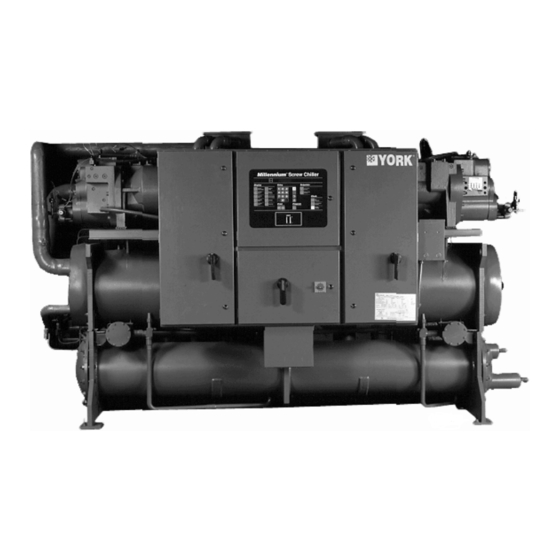
- Page 1 YCWS WATER COOLED LIQUID CHILLERS INSTALLATION, OPERATION AND New Release Form 201.24-NM2 (601) MAINTENANCE YCWS WATER COOLED LIQUID CHILLERS YCWS0313SC – 0663SC 00546VIP 50 HERTZ STYLE B REFRIGERANT TYPE: R-22...
-
Page 2: Table Of Contents
Power Supply Options (All Models) ....18 Chilled Liquid Pump ........... 28 Single-Point Power Supply Connection ..... 18 Common Run Signal ........... 28 Multiple Point Power Supply Connection (Standard) ............18 System Alarm ............28 Building Automation System (BAS) Interface ... 18 YORK INTERNATIONAL... - Page 3 1.23 Pumpdown (LLSV) Control .................... 43 1.24 Lead / Lag Compressor Selection ................... 43 2. CONTROL PANEL PROGRAMMING AND DATA ACCESS ........... 44 Display and Status Keys ....................44 Program and Setup Keys ....................44 3. STATUS KEYS ............................. 45 General ..........................45 YORK INTERNATIONAL...
- Page 4 Slide Valve Position ......................68 Compressor Starting and Loading Sequence ..............68 Compressor Loading ....................... 69 Loading Limiting ......................69 Compressor Unloading and Shutdown Sequence ............69 7.10 Local Cooling Setpoints Key ..................69 7.11 Remote Cooling Setpoints Key ..................70 YORK INTERNATIONAL...
- Page 5 Isolator Selection Data .......................... 98 Isolator Details ............................99 Compressors ............................100 SECTION SPARE PARTS ......................101 Recommended Spare Parts ........................101 Recommended Compressor Oils ......................101 Associated Drawings ..........................101 SECTION DECOMMISSIONING, DISMANTLING AND DISPOSAL ........102 General ..............................102 YORK INTERNATIONAL...
-
Page 6: Introduction
Center. See Commissioning, page 33. specified in this manual. • Only genuine YORK approved spare parts, oils and This manual contains all the information required for refrigerants must be used. -
Page 7: Responsibility For Safety
This manual and any other document supplied with the unit, are the property of YORK which reserves all rights. Electrical They may not be reproduced, in whole or in part, with- The unit must be grounded. -
Page 8: Refrigerants And Oils
For more comprehensive information on electrical supply from the control system, thus shutting safety precautions for use of refrigerants and oils, refer down the unit. to the Materials Safety Data tables provided on pages 9 through 11. YORK INTERNATIONAL... -
Page 9: Material Safety Data
Fire Extinguishing Data Non-flammable. Containers Fire exposed containers should be kept cool with water sprays. Containers may burst if overheated. Fire Fighting Self contained breathing apparatus and protective clothing must be worn in fire conditions. Protective Equip. YORK INTERNATIONAL... - Page 10 General Chiller Information & Safety MATERIAL SAFETY DATA Section 1 – PRODUCT NAME AND INFORMATION Product (Trade Name and Synonyms): YORK “L” Oil Chemical Name: Ester Chemical Family: Polyol Ester Formula: Proprietary CAS#: Proprietary Section 2 – COMPONENTS AND HAZARD STATEMENT This product is non-hazardous.
- Page 11 The information in this material safety data sheet should be provided to all who use, handle, store, transport, or are otherwise exposed to this product. YORK believes the information in this document to be reliable and up to date as of the date of publication, but makes no guarantee that it is.
- Page 12 THIS PAGE INTENTIONALLY LEFT BLANK TO MAINTAIN PAGE FORMAT. YORK INTERNATIONAL...
-
Page 13: Compressor
The 50 Hz motor operates at 2950 rpm to direct drive the male rotor which in turn drives the female rotor on a light film of oil. YORK YCWS chillers are designed for water or wa- ter-glycol cooling. Each compressor is direct drive, semi-hermetic, rotary twin screw type and includes the following items: All models are designed for indoor installation. - Page 14 A 350 watt (115V 1 Ø 50 Hz) immersion heater is lo- ing load. cated in the compressor. The heater is temperature ac- tivated to prevent refrigerant condensation. YORK INTERNATIONAL...
-
Page 15: Oil Separator
The oil level should never be above the Water vent and drain connections are included. The top of the “upper” sight glass. cooler is insulated with flexible closed-cell foam. YORK INTERNATIONAL... -
Page 16: Power And Control Panels
10% FLA and shuts The standard functions include: water or glycol cool- the system down. ing, automatic pump down, demand load limiting from YORK INTERNATIONAL... -
Page 17: Motor Protector Module
(refer to Section 5 for Status Key details). Integral trip curves allow for in-rush currents This key provides a display of the current operational during Star/Delta and DOL starting without nuisance and/or fault status of the unit or the individual refriger- tripping. YORK INTERNATIONAL... -
Page 18: Display Keys
BAS. six safety shutdowns. Entry Keys A YORK ISN Building Automation System can provide a Pulse Width The numeric and associated keys are used for enter- Modulated (PWM) signal direct to the ing data required for programming the chiller. -
Page 19: Flange Kits (150 Psi)
Language LCD and Keypad Printer Standard display language and keypad is English. Span- Hand held printer for obtaining printout of unit operat- ish is available as an option. ing data and history data. YORK INTERNATIONAL... -
Page 20: Nomenclature
5 6 7 8 11 12 13 14 15 BASE PRODUCT TYPE NOMINAL CAPACITY UNIT DESIGNATOR REFRIGERANT VOLTAGE/STARTER DESIGN / DEVELOPMENT LEVEL :Design Series F : YORK Standard Unit :R-22 :Engineering :Wye-Delta : Chiller Change : Water Cooled or PIN Level : Screw... -
Page 21: And Storage Delivery And Storage
Sales Order. Major damage must be reported immediately to your If the unit is to be put into storage, before installation, local YORK representative. the following precautions should be observed: Ensure that all openings, such as water connections, MOVING THE UNIT are securely capped. -
Page 22: Lifting By Fork Lift
AT COMPRESSOR TERMINAL BOX USING THE 2 LIFTING LUGS END SEE DETAIL ABOVE (SUPPLIED AS AN ACCESSORY) NOTE: DISCONNECT THE NUMBERED CONTROL WIRING INSIDE THE PANEL UNFASTEN 6 BOLTS ON CONTROL PANEL CROSS MEMBER LD06595 FIG. 5 – CONTROL PANEL REMOVAL YORK INTERNATIONAL... -
Page 23: Installation Of Vibration Isolators
(3) so that a concrete base can be poured and having a 1" N.P.T. connection can resting on the ground (1) , with a corkboard (4) installed be obtained from YORK as an option on both sides, and a waterproof sealing compound (5). for the unit. -
Page 24: Water Treatment
Aerated, brackish or salt water is not recommended for use in the water system(s). YORK recommends that a • Thermometer and pressure gauge connections water treatment specialist is consulted to determine that... -
Page 25: Pipework Arrangement
FIG. 9 – COOLER CONNECTIONS TABLE 2 – CONDENSER / COOLER CONNECTIONS NOMINAL LD06598 SIZE 8" 8-5/8" ±1/32" 7/16 ±1/32" 8.416" FIG. 7 – CONDENSER COOLING LIQUID SYSTEM 6" 6-5/8" ±1/32" ±1/32" 6.433" ±1/32" ±1/32" 5" 5-9/16" 5.395 YORK INTERNATIONAL... -
Page 26: Option Flanges
L = length of pipe in meters tended to ensure safe and satisfactory operation of the C = value in table below unit. Failure to follow these recommendations could cause harm to persons, or damage to the unit, and may invalidate the warranty. YORK INTERNATIONAL... -
Page 27: Power Wiring
If the switch is set to the “ON” position before using the wire sizes detailed in Section 9. commissioning then it must be reported to YORK, oth- Connect each of the earth grounds to the main protec- erwise the warranty may be invalidated. -
Page 28: Control Panel Wiring
Closure of suitable contacts connected to terminals 28 start/stop for the pump in conjunction with the daily and 13 will enable a hard copy printout of Operating start/stop schedule. If no schedule is set, and the cus- Data/Fault History to be obtained (an optional printer YORK INTERNATIONAL... -
Page 29: Remote Setpoint Offset - Temperature
Remote Setpoint Offset – Temperature (PWMT) offset of EMS% CURRENT LOAD LIMIT. Timed closure of suitable contacts connected to termi- nals 27 and 13 (PWM contacts) will give remote offset function of the chilled liquid setpoint if required. YORK INTERNATIONAL... -
Page 30: Connection Diagrams
Installation CONNECTION DIAGRAM LD06947 FIG. 12 – MULTI POINT POWER SUPPLY CONNECTION - STANDARD UNIT LD06948 FIG. 13 – SINGLE-POINT POWER SUPPLY WITH INTERNAL CIRCUIT BREAKER OR NON-FUSED DISCONNECT SWITCH YORK INTERNATIONAL... - Page 31 2. The above recommendations are based upon the National Electric Code and the use of copper connectors only. Field wiring must comply with local codes. 3. Single point Non-Fused Disconnect Switch is not offered with additional separate Non-Fused Disconnect Switches YORK INTERNATIONAL...
-
Page 32: Connection Diagram Legend And Notes
The voltage to these circuits is removed when the common point of isolation to the unit is opened. This common point of isolation is not supplied by YORK. The YORK voltage free contacts are rated at 125VA. All inductive devices (relays) switched by the YORK voltage free contacts must have their coil suppressed using standard R/C suppressors. -
Page 33: Commissioning
Control panel: Check the panel to see that it is free of by YORK Authorized personnel. If the switch has been foreign materials (wire, metal chips, etc.) and clean out set to the ‘ON’ position before commissioning then it if required. -
Page 34: First Time Start-Up
Ensure the cooling liquid temperature sensor is coated Interlocks: Verify that liquid is flowing through the with heat conductive compound (Part No. 013-00890- cooler and that heat load is present. Ensure that any re- YORK INTERNATIONAL... - Page 35 ‘ON’ position and restart liquid refrigerant will be seen in the liquid line sight glass. the unit. Check that loading occurs as specified in the MBCS and that general operation is correct. After several minutes operation and providing a full charge YORK INTERNATIONAL...
- Page 36 Commissioning THIS PAGE INTENTIONALLY LEFT BLANK TO MAINTAIN PAGE FORMAT. YORK INTERNATIONAL...
-
Page 37: Section 6 Unit Operation
The units are designed to work independently, or in on the lead compressor, the control system will adjust conjunction with other equipment via a YORK ISN the unit load depending on the chilled liquid tempera- building management system or other automated con- ture and rate of temperature change. -
Page 38: Section 7 Micropanel
ARB boards, and the 40 character display to operate the energized, both sides of the relay coils or triacs will be integrated circuitry. The 24VAC is filtered, but not regu- at +12VDC potential. lated, to provide unregulated + 24VDC to supply the YORK INTERNATIONAL... -
Page 39: Circuit Breakers
The logic section of the control panel compressor if motor cooling is inadequate. contains the relay output boards (ARB), which have 115VAC connected The onboard CTs provide 3-phase current protection to them. which look at phase current and send an analogue sig- YORK INTERNATIONAL... -
Page 40: Remote Start/Stop
The maximum allowable running current for each com- signal. After 30 minutes, if no refresh is provided, the pressor can be adjusted remotely to a lower value us- setpoint will change back to its original value. ing repeated timed closure of ‘voltage free’ contacts YORK INTERNATIONAL... -
Page 41: Remote Setpoint Reset
Kit is connected to the microproces- cessor will ignore closures of less than 1 second. sor. The Remote Control Center will To calculate the necessary contact closure time to pro- always determine the setpoint. vide a required Reset, use the following steps: YORK INTERNATIONAL... -
Page 42: Control Panel
1.18 CHILLED LIQUID PUMP CONTACT ‘PROGRAM’ key to ‘MANUAL’. ‘MANUAL’ restart requires a reset us- YORK provides a voltage free contact terminals 5 and 6 ing the unit ON/OFF switch under the which close to start a pump. This contact can be used as keypad. -
Page 43: Anti-Coincidence Timer
The compressor continues to operate to try to maintain chilled liquid temperature as close to until it either pumps down to the low suction pressure setpoint as possible. cutout setting or for 180 seconds, whichever comes first. YORK INTERNATIONAL... -
Page 44: Control Panel Programming And Data Access
This key is used for display and programming of the This switch shuts down the entire chiller when placed chiller operational settings and limits. in the ‘OFF’ position. The switch must be ‘ON’ for the chiller to operate. YORK INTERNATIONAL... -
Page 45: Status Keys
S W I T C H for systems 3 and 4 should only be in the ‘ON’ position T H E O F F P O S I T I O N for three and four system models respectively. YORK INTERNATIONAL... -
Page 46: Unit Warnings
P U M P I N G D O W N The chilled liquid temperature is below the point where Both refrigerant systems are in a pump-down cycle. the microprocessor will bring the lead system on and/ Pump down display messages occur on shutdowns YORK INTERNATIONAL... -
Page 47: Anticipation Control Status Messages
This message should never appear, if it does consult the high pressure cutout. your local YORK office. This message is a warning that the setting for the type of refrigerant used with the The operation of this safety is important if condenser unit has been tampered with and the unit will not run. -
Page 48: Unit Fault Status Messages
Closing of the flow switch, when flow is present, will The cutout is programmable and can be set for lower cause the message to disappear and auto-restart to occur. limit values if required. YORK INTERNATIONAL... -
Page 49: System Fault Status Messages
This type of oil failure will not be picked up by the High Oil Differential Safety since no flow will cause This cutout protects the compressor rotors from dam- the differential through the oil piping to drop to zero. age due to overheating, expansion, and breakdown of YORK INTERNATIONAL... - Page 50 3 bar for R-22 and R407C are recommended. SUCTION PRESSURE = PROGRAMMED CUTOUT * (RUN TIME - 25) If the switch is set for ‘Brine Cooling’ (glycol) the cut- CUTOUT out is programmable between 0.3 to 5 bar for both R- YORK INTERNATIONAL...
- Page 51 6 = OUT OF RANGE DIP SWITCH SETTINGS pressor that is not pumping due to a mechanical mal- function. Motor current is monitored using 3 current 7 = UNBALANCE > 50% transformers (CTs) per motor, one on each phase. 8 = PHASE LOSS YORK INTERNATIONAL...
-
Page 52: Printout On Fault Shutdown
A fault lock-out will result if safety thresholds are ex- ceeded three times in a 90 minute period. present, occasional faults may occur with the corresponding automatic print- out. This is not a cause for concern. YORK INTERNATIONAL... -
Page 53: Display Keys
• Discharge superheat 4.2 CHILLED LIQUID TEMPS KEY • Compressor slide valve position When the key is pressed the chiller leaving chilled liq- • Cooler inlet refrigerant temperature uid temperature (LCHLT) and returning chilled liquid temperature (RCHLT) are displayed. YORK INTERNATIONAL... -
Page 54: Ambient Temp Key
(converted from pressure) and the actual. I S N C R N T L I M I T : N O N E E M S C R N T L I M I T : N O N E YORK INTERNATIONAL... -
Page 55: Operating Hrs / Start Counter Key
W A T E R Open: Water cooling mode is for water cooling applications S 1 - 4 Y C W S and allows the chilled liquid leaving temperature set- point to be programmed from 4.4 to 21.1°C. YORK INTERNATIONAL... -
Page 56: Dip Switch Settings
The FUNCTION Key can be used to scroll through the displays for: 4.9 FUNCTION KEY • Chilled Liquid Temps • System # Data Pressing this key displays the same message as press- ing the ‘STATUS’ key. • Motor Current • Options YORK INTERNATIONAL... -
Page 57: Print Keys
S Y S T E M N U M B E R 5.3 OPER DATA -– LOCAL DISPLAY MESSAGES This message advises which system is programmed as When the ‘OPER DATA’ key is pressed, the following message appears: the lead. YORK INTERNATIONAL... - Page 58 The following sequence of three displays are provided first for System 1 and then for Systems 2: S Y S R U N T I M E 1 1 - 1 5 - 1 0 D - H - M - S YORK INTERNATIONAL...
-
Page 59: Oper Data - Remote Printout
5.4 OPER DATA - REMOTE PRINTOUT The following shows a typical example YCWS print- out obtained by pressing the ‘OPER DATA’ key with an optional printer attached. YORK INTERNATIONAL CORPORATION MILLENNIUM SCREW CHILLER SYSTEM 1 DATA UNIT STATUS COMPRESSORS STATUS... -
Page 60: History Key
P R E S S U R E After the ‘ENTER’ Key is pressed, a message indicat- U N L O A D 2 5 . 8 5 B A R G ing the time and date of the Fault Shutdown will appear: YORK INTERNATIONAL... - Page 61 L E A D S Y S T E M • Wye-Delta timer output. S Y S T E M N U M B E R YORK INTERNATIONAL...
- Page 62 4 9 . 6 ° C S Y S # S A T D S C H = 5 4 . 4 ° C S U C T H E A T 1 2 . 5 ° C YORK INTERNATIONAL...
-
Page 63: History - Remote Printout
Two refrigerant system chillers will provide a history printout of the last 6 faults. An example of the first of the 6 HISTORY Printouts is shown below: YORK INTERNATIONAL CORPORATION SYSTEM 1 DATA MILLENNIUM SCREW CHILLER WATER COOLED LIQUID CHILLER... -
Page 64: Local Printer Option
‘PRINT’ KEY Section. printer). • Serial printer should be set for data bits=8 YORK offer a kit which includes a printer which has parity=none and baud rate=1200. an internal Ni-cad battery, a roll of paper, a ‘D’ type •... - Page 65 These conditions will be stored in memory until they can be transmitted to the or the microprocessor board. YORK assumes no re- sponsibility for assistance or damage in the use of non- printer and printed.
-
Page 66: Entry Keys
If this is not done, the new values entered will the cursor is over ‘AM’ or ‘PM’ on the display. For be lost and the original values will be restored. example, pressing the ‘á’ key when the cursor is on ‘PM’ changes it to ‘AM’. YORK INTERNATIONAL... -
Page 67: Setpoint Keys And Chilled Liquid Control
This is accomplished by analyzing the temperature er- point and the range. The range and is the maximum ror (ERROR) and the rate of change (RATE) to deter- acceptable + and - deviation from setpoint. mine the amount of loading necessary to cool the chilled YORK INTERNATIONAL... -
Page 68: Slide Valve Control
• The lag compressor will then be loaded until it also reaches a slide valve step of ‘40’ while the lead Fixed timers are set to minimize undershoot and over- compressor is maintained at a constant load. shoot as a result of slide valve control. YORK INTERNATIONAL... -
Page 69: Compressor Loading
10 steps between sys- tems 1 and 2. It could only load system 1 ‘2’ steps while loading system 2 ‘8’ steps. Under these circumstances, the two systems will not appear to equalize loading. YORK INTERNATIONAL... -
Page 70: Remote Cooling Setpoints Key
This feature application, remembering to use a leading ‘0’ for val- ues less than 10°C. Press the ‘ENTER’ key to store the is typically used for demand limiting or ice storage applications. new value in memory. YORK INTERNATIONAL... -
Page 71: Clock Keys
Press ‘ENTER’ to move to the hour part of the display. disappear and the ‘live’ clock will be Next, key in the time (hours/minutes) using a leading displayed. ‘0’ for times before 10 o’clock. e.g. 08:31. YORK INTERNATIONAL... -
Page 72: Set Schedule/Holiday Key
‘*’ key. If a day marked as a holiday is grammed for the remainder of the not to be a holiday, press the ‘*’ key. week to the Monday schedule. When the ‘*’ key is pressed, the cursor will advance to YORK INTERNATIONAL... -
Page 73: Manual Override Key
Chiller ‘ON/OFF’ switch is ‘ON’, remote cycling to be repeated to bring the chiller back devices are closed, and system switches permit. on line. Normally this key is only used for servicing when the YORK INTERNATIONAL... -
Page 74: Program Keys
13.8 and 27.52 bar. If an unacceptable value is entered at any stage, the following message is displayed for a few seconds and the entered value is ignored: YORK INTERNATIONAL... - Page 75 T E M P C U T O U T 5 4 . 0 ° C PROGRAMMED X RUN TIME / 3 +10 CUTOUT The high ambient temperature cutout is used to select the ambient temperature above which the chiller may YORK INTERNATIONAL...
- Page 76 The anti-recycle timer controls the minimum time be- set at 2.2°C and cannot be reprogrammed. tween starts for each compressor. This is the time avail- If the Dip Switch (S1) on the AMB board is set for ‘GLY- YORK INTERNATIONAL...
-
Page 77: Input/Output Display Routine
‘á’ or ‘â’ keys are used to change from ‘AUTO- • Voltage read on input MATIC’ to ‘MANUAL’ lead/lag. • Converted value (example: 3.75 BARG) If ‘MANUAL’ control is desired, press the ‘á’ or ‘â’ key. One of the following messages will be displayed: YORK INTERNATIONAL... - Page 78 TO 3.3 BARG WATER GLYCOL HIGH AMBIENT TEMP CUTOUT 45.0°C STANDARD LOW AMBIENT TEMP CUTOUT -3.9°C STANDARD LEAVING LIQUID TEMP CUTOUT 2.2°C WATER -12.9 to 2.2°C GLYCOL HIGH MOTOR CURRENT UNLOAD 30 to 105% FLA ANTI-RECYCLE TIME 300 - 600 SECONDS YORK INTERNATIONAL...
-
Page 79: Ems / Bas Interface Card Kits
“REM SETP = XXX°F” * Max Reset Value is the “Max EMS-PWM Remote Temp. Reset” setpoint value described in the programming section under Cooling Setpoints. Programmable values are from 2°F to 40°F (1.11°C to 22.22°C). YORK INTERNATIONAL... - Page 80 NOTE: The coil of any added relay used for reset must be suppressed to prevent possible component f a 4-20mA signal is available, it is applied to terminals damage. Use YORK PN031-00808-000 A+ and A- and jumpers are applied to JU5 and JU3 suppressor.
-
Page 81: Section 8 Maintenance
If damage or a system failure occurs due to tations given in the MBCS manual. improper maintenance during the warranty period, YORK shall not be liable for costs incurred to return Compressor Oil Level: Check the compressor oil level the unit to satisfactory condition. -
Page 82: Standard Units
Check low and high ambient cutout functions. controls: Check program settings. Check low LCHLT cutout function. Check HP / LP cutout functions. Check low differential oil pressure function. Check pump-down function. Check low evaporator temperature cutout function. Check load / unload function. YORK INTERNATIONAL... -
Page 83: Competent Persons Troubleshooting Guide
Check the compressor unloads correctly. Measured temperature is incorrect. Check sensor calibration, location and wiring. Chiller FAULT: VAC Poor mains supply voltage. Check mains supply is stable and within allowable UNDERVOLTAGE limits. displayed Check for voltage dip on compressor start. YORK INTERNATIONAL... - Page 84 Check operation of motor cooling, TEVs and liquid solenoid valve. SYS # CURR LIMITING High compressor motor current Check liquid temperature is within operating limits. displayed has activated unloading. Check if ambient air temperature is above unloading). (Compressor current operating limits. YORK INTERNATIONAL...
-
Page 85: Sensor Calibration Charts
TEST POINT: Discharge Pressure (BSP): Ambient Air (BAMB) ..........AMB J11-9/6 Refrigerant Circuit 1 ........... AMB J15-8/3 Refrigerant Circuit 2 ........... AMB J15-7/1 Suction Pressure (BSP): Refrigerant Circuit 1 ........... AMB J13-7/1 Refrigerant Circuit 2 ........... AMB J14-7/1 YORK INTERNATIONAL... -
Page 86: Typical Control Panel Wiring
Maintenance TYPICAL CONTROL PANEL WIRING YORK INTERNATIONAL... - Page 87 FORM 201.24-NM2 TYPICAL CONTROL PANEL WIRING YORK INTERNATIONAL...
-
Page 88: Section 9 Technical Data
CURVE MODEL *Review cutoff limits YCWS0313SC, in Design Parameters H,K,M YCWS0373SC - 0663SC* Table FIG. 22 – COOLER WATER PRESSURE DROP LD06951 CURVE MODEL YCWS0313SC, 0373SC, 0423SC YCWS0503SC, 0563SC YCWS0613SC, 0663SC FIG. 23 – CONDENSER WATER PRESSURE DROP YORK INTERNATIONAL... - Page 89 TABLE 13 – RECOMMENDED GLYCOL SOLUTION STRENGTHS Propylene Glycol Ethylene Glycol Concentration Concentration LCHLT °C % w/w % w/w LD06934 A = Correction Factor B = Temperature C = Concentration % Through Cooler FIG. 24 – GLYCOL SOLUTION STRENGTHS YORK INTERNATIONAL...
-
Page 90: Physical Data / Sound Data
Sound Pressure Levels (SPL), dB re 20 microPa in accordance with ARI Standard 575-94 TABLE 15 – SOUND DATA WEIGHTED MODEL COMP. dB ‘A’ YCWS0313SC YCWS0373SC YCWS0423SC YCWS0503SC YCWS0563SC YCWS0613SC YCWS0663SC NOTE: All ‘A’ weighted sound pressure data ± 3 dBA... - Page 91 FORM 201.24-NM2 THIS PAGE INTENTIONALLY LEFT BLANK TO MAINTAIN PAGE FORMAT. YORK INTERNATIONAL...
-
Page 92: Electrical Data
SYSTEM #1 VOLT MAX DUAL CHILLER MIN NF CODE CIR. DUAL FUSE MODEL DISC SW FUSE MAX CB YCWS0313SC YCWS0373SC YCWS0423SC YCWS0503SC YCWS0563SC YCWS0613SC YCWS0663SC INCOMING WIRE SIZE (FIELD SUPPLIED WIRING) SYSTEM #2 SYSTEM #1 VOLT CHILLER TERM TERM... - Page 93 FORM 201.24-NM2 ELECTRICAL DATA SYSTEM #2 VOLT MAX DUAL CHILLER MIN NF CIR. DUAL CODE FUSE MODEL DISC SW FUSE MAX CB YCWS0313SC YCWS0373SC YCWS0423SC YCWS0503SC YCWS0563SC YCWS0613SC YCWS0663SC YORK INTERNATIONAL...
- Page 94 SYSTEM #1 SYSTEM #2 VOLT MAX DUAL MIN N/F CHILLER DUAL CODE FUSE DISC SW MODELS FUSE MAX CB YCWS0313SC YCWS0373SC YCWS0423SC YCWS0503SC YCWS0563SC YCWS0613SC YCWS0663SC INCOMING WIRE SIZE (FIELD SUPPLIED WIRING) SYSTEM #1 & #2 VOLT CHILLER CODE TERM...
- Page 95 This disconnect is not intended to be a Load Break Device. 9. Field Wiring by others which complies to the National Electrical Code & Local Codes. YORK INTERNATIONAL...
-
Page 96: Dimensions
Technical Data DIMENSIONS – MODELS YCWS0313SB-0663SB Different for every Model MODEL DIM. YCWS0313SC YCWS0373SC LD06952 YCWS0423SC YCWS0503SC YCWS0563SC YCWS0613SC YCWS0663SC LD06953 All dimensions are in mm unless otherwise noted. LD06954 FIG. 25 – MODELS YCWS0313SB - YCWS0663SB DIMENSIONS YORK INTERNATIONAL... - Page 97 1111 1111 1038 1038 1038 1038 1038 1038 1038 NOTES: 1. CLEARANCES - Recommended YORK clearances to service the unit are as follows: Rear to Wall: 508mm Front to Wall: 813mm Top: 508mm Tube cleaning and removal: 2438mm (either end) 2.
-
Page 98: Isolator Selection Data
Technical Data ISOLATOR SELECTION DATA 50 HERTZ WEIGHT DISTRIBUTION BY MODEL TOTAL MODEL WEIGHT YCWS0313SC 2758 YCWS0373SC 3098 YCWS0423SC 3249 YCWS0503SC 3801 YCWS0563SC 3862 YCWS0613SC 1060 1060 1074 1074 4268 YCWS0663SC 1071 1071 1089 1089 4321 LD06956 1" ISOLATOR SELECTIONS - VMC TYPE CP-2- X... -
Page 99: Isolator Details
DEFL. SPRING & SIZE LBS. COLOR CP-2-28 1800 816.4 1.02 25.9 GREEN CP-2-31 2200 997.9 0.83 21.0 GRAY CP-2-32 2600 1179.3 0.74 18.7 WHITE CP-2-35 3000 1360.8 0.70 17.7 GOLD NEOPRENE ISOLATOR DETAILS LD01089 TYPE R-4 OR RD-4 YORK INTERNATIONAL... -
Page 100: Compressors
- XCMTB COMPRESSOR MOTOR TERMINAL BOX - BOP OIL PRESSURE -YSV SOLENOID VALVE - BOT OIL TEMPERATURE - YLLSV LIQUID LINE SOLENOID VALVE - BSP SUCTION PRESSURE - ZCPR COMPRESSOR - BST SUCTION TEMPERATURE FIG. 27 – COMPRESSORS YORK INTERNATIONAL... -
Page 101: Section 10 Spare Parts
FORM 201.24-NM2 SECTION 10 SPARE PARTS This information will be available at a later date. YORK INTERNATIONAL... -
Page 102: Section 11 Decommissioning, Dismantling And Disposal
If no isolation valves are installed it may be Only use lifting equipment of ad- necessary to drain the complete system. equate capacity. After removal from position the unit parts may be dis- posed of according to local laws and regulations. YORK INTERNATIONAL... - Page 103 FORM 201.24-NM2 NOTES YORK INTERNATIONAL...
- Page 104 P.O. Box 1592, York, Pennsylvania USA 17405-1592 Tele. 800-861-1001 Subject to change without notice. Printed in USA Copyright © by York International Corporation 2001 www.york.com ALL RIGHTS RESERVED Form 201.24-NM2 (601) New Release...