
Related Manuals for Mercedes-Benz OM 471


Summary of Contents for Mercedes-Benz OM 471
- Page 1 Introduction of engine OM 471 and exhaust aftertreatment Introduction into Service Manual – This printout will not be recorded by the update service. Status: 09 / 2011 –...
- Page 2 Mercedes>Benz Service Introduction of engine OM 471 and exhaust aftertreatment Technical status 01.09.2011 Daimler AG Technical Information and Workshop Equipment(GSP/OI) D$70546 Stuttgart – This printout will not be recorded by the update service. Status: 09 / 2011 –...
- Page 3 Information and copyright Product portfolio You can also find comprehensive information about our complete product portfolio on our Internet portal: Link: http://aftersales.mercedes>benz.com Questions and suggestions If you have any questions or suggestions concerning this product, please write to us. E>Mail: customer.support@daimler.com Telefax: +49>(0)18 05/0 10>79 78...
- Page 4 Any changes or supplements hereto will be published in the Workshop Information System (WIS) only. Additional documents for the OM 471 engine and the EATS, such as maintenance and repair instructions or wiring diagrams are also available in the Workshop Information System (WIS).
-
Page 5: Table Of Contents
Overview of as>built configuration and function descriptions 2.8.11 ENGINES 471.9 Overview of new features Page 10 Engine OM!471 Page 11 Technical data of diesel engine OM 471 As>built configuration descriptions Page 12 Cylinder head cover, as>built configuration Page 13 Cylinder head, as>built configuration Page 18 Cylinder head gasket, as>built configuration... -
Page 6: Component Descriptions
Fuel high pressure circuit function Component descriptions Page 101 Central gateway control unit (CGW), component description Introduction of engine OM 471 and exhaust aftertreatment > 09/2011 > – This printout will not be recorded by the update service. Status: 09 / 2011 –... -
Page 7: Table Of Contents
Contents Page 102 Component description drive control (CPC) control unit Page 103 Component description for engine management (MCM) control unit Page 105 Electronic Brake Control control unit (EBS), A10b, A10c component description Page 106 Parameterizable special module (PSM) control unit component description Page 107 Battery disconnect switch control unit, component description... -
Page 8: Table Of Contents
Vehicles with code (M5R) Engine version EEV and vehicles with code (M5Y) Engine version Euro V Introduction of engine OM 471 and exhaust aftertreatment > 09/2011 > – This printout will not be recorded by the update service. Status: 09 / 2011 –... -
Page 9: Table Of Contents
Contents Page 141 Vehicles with code (M5Z) Engine version Euro VI Page 142 AdBlue fill level sensor/temperature sensor, component description Page 144 Coolant pressure control sensor, component description i Only in vehicles with code (B3H) Secondary water retarder. Page 145 Component description for crankshaft B600 position sensor... -
Page 10: Table Of Contents
Coolant pressure control solenoid valve, component description i Only in vehicles with code (B3H) Secondary water retarder. Introduction of engine OM 471 and exhaust aftertreatment > 09/2011 > – This printout will not be recorded by the update service. Status: 09 / 2011 –... -
Page 11: Table Of Contents
Contents Page 170 Component description for fuel injectors Y608. to Y613 Page 174 Component description for the Y616, Y616 b1 electromagnetic viscous coupling Page 176 Component description for exhaust gas Y621 recirculation controller Page 178 Component description for engine brake Y624, Y625 solenoid valve Page 180... -
Page 12: This Printout Will Not Be Recorded By The Update Service. Status
Engine version Euro VI. Page 221 Heating system heat exchanger, component description Introduction of engine OM 471 and exhaust aftertreatment > 09/2011 > – This printout will not be recorded by the update service. Status: 09 / 2011 –... -
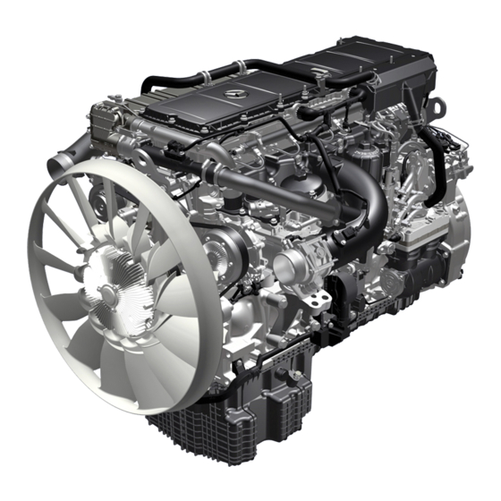
Page 13: Engine Om!471
Oil/coolant module Turbocharger The engine OM 471 is the first 6>cylinder inline engine with two The OM 471 engine is available in four output stages between 310 overhead camshafts to be used in a Mercedes>Benz commercial and 375 kW. -
Page 14: Technical Data Of Diesel Engine Om 471
36,4 Crankcase, cylinder liner (wet) OM 471 Cylinder diameter (mm) Cylinder distance (mm) Introduction of engine OM 471 and exhaust aftertreatment > 09/2011 > – This printout will not be recorded by the update service. Status: 09 / 2011 –... -
Page 15: Cylinder Head Cover, As>Built Configuration
As>built configurations GF01.20>W>0801H Cylinder head cover, as>built configuration 1.7.11 ENGINES 471.9 Cylinder head cover Prefilter Elastomer element Elastomer seal Direction of travel W01.20>1046>76 The cylinder head cover (1) consists of plastic and, on the one For acoustic decoupling of the cylinder head cover (1) an hand, prevents ingress of water and foreign objects into the valve elastomer element (3) is inserted in all through holes which serve assembly. -
Page 16: Cylinder Head, As>Built Configuration
Introduction of engine OM 471 and exhaust aftertreatment > 09/2011 > – This printout will not be recorded by the update service. Status: 09 / 2011 –... - Page 17 As>built configurations Intake ports Threaded holes for the charge air manifold attachment Direction of travel W01.30>1122>76 Exhaust ducts Threaded holes for the charge air manifold attachment Direction of travel W01.30>1123>76 – This printout will not be recorded by the update service. Status: 09 / 2011 –...
- Page 18 Inlet valves Exhaust valves Bores for the fuel injectors Direction of travel W01.30>1125>76 Introduction of engine OM 471 and exhaust aftertreatment > 09/2011 > – This printout will not be recorded by the update service. Status: 09 / 2011 –...
- Page 19 As>built configurations OiI overflow holes from cylinder crankcase to cylinder head Oil return flow openings or oil return flow holes from cylinder head to cylinder crankcase Direction of travel W01.30>1126>76 Coolant short>circuit channel from cylinder head to cylinder crankcase Coolant overflow holes from cylinder crankcase to cylinder head Direction of travel W01.30>1127>76...
- Page 20 (53) of the cylinder head. Introduction of engine OM 471 and exhaust aftertreatment > 09/2011 > – This printout will not be recorded by the update service. Status: 09 / 2011 –...
-
Page 21: Cylinder Head Gasket, As>Built Configuration
As>built configurations GF01.30>W>0801H Cylinder head gasket, as>built configuration 1.7.11 ENGINES 471.9 Upper side of the cylinder head seal OD Engine oil feed openings Engine oil return opening WR Coolant bypass duct opening WZ Coolant feed opening Opening for the blow>by duct to the crankcase ventilation system Direction of travel W01.30>1120>06... -
Page 22: Crankcase As>Built Configuration
Oil return duct from oil separator for Oil hole closed off laterally crankcase ventilation system Direction of travel Introduction of engine OM 471 and exhaust aftertreatment > 09/2011 > – This printout will not be recorded by the update service. Status: 09 / 2011 –... - Page 23 As>built configurations Crankcase from below, shown with oil ducts Oil return duct to oil/coolant module Oil return ducts to oil pan Direction of travel W01.40>1146>76 Crankcase from below, shown with oil ducts Bores for oil supply to the oil spray nozzles Bores for oil supply to the main bearing, crankshaft and connecting...
-
Page 24: Connecting Rod, As>Built Configuration
A connecting rod bushing (3) is pressed into a small connecting rod small end (2). Introduction of engine OM 471 and exhaust aftertreatment > 09/2011 > – This printout will not be recorded by the update service. Status: 09 / 2011 –... -
Page 25: Piston, As>Built Configuration
1st piston ring 2nd piston ring Oil scraper ring Bolt eye Piston skirt Piston bolt circlip Piston pin Cooling duct W03.10>1124>76 Feature OM 471 Version Two piece Material Steel Weight (with spring steel sheet) 3,339 KG Piston diameter 132 mm Bolt diameter... -
Page 26: Crankshaft, As>Built Configuration
The crankshaft bearing journals (1) and the connecting rod journals (2) are inductively hardened and ground in the surface layer. Introduction of engine OM 471 and exhaust aftertreatment > 09/2011 > – This printout will not be recorded by the update service. Status: 09 / 2011 –... -
Page 27: Valve Control; As>Built Configuration
As>built configurations GF05.00>W>0800H Valve control; as>built configuration 1.7.11 ENGINES 471.9 Valve control overall Exhaust rocker arm Exhaust rocker arm with hydroelement Brake rocker arm Exhaust rocker arm spindle Drive gear for exhaust camshaft Exhaust camshaft Outlet valve Valve spring Intake rocker arm Intake rocker arm spindle Drive gear for intake camshaft Intake camshaft... - Page 28 Oil duct for cylinders 1 and 3 Oil duct for cylinders 4 and 6 W05.00>1035>75 Introduction of engine OM 471 and exhaust aftertreatment > 09/2011 > – This printout will not be recorded by the update service. Status: 09 / 2011 –...
- Page 29 As>built configurations W05.00>1036>01 W05.00>1037>01 W05.00>1038>01 Design of the rocker arm Exhaust rocker arm Exhaust rocker arm with Brake rocker arm Rocker arm roller hydroelement Rocker arm roller Adjusting element for adjusting the Rocker arm roller Adjusting element for engine brake valve clearance Adjusting element for adjusting the Oil inlet hole...
- Page 30 Intake rocker arm spindle Intake camshaft Inlet valves Adjusting elements for adjusting the valve clearance W05.00>1039>82 Introduction of engine OM 471 and exhaust aftertreatment > 09/2011 > – This printout will not be recorded by the update service. Status: 09 / 2011 –...
- Page 31 As>built configurations Design of the intake rocker arm spindle (10) Intake rocker arm spindle Lubricating oil duct W05.00>1040>75 Design of the intake rocker arm (9) Intake rocker arm Rocker arm roller Adjusting elements for adjusting the valve clearance Every cylinder is assigned to an intake rocker arm (9) for valve timing for the inlet side over which the two intake valves (13) are actuated respectively.
-
Page 32: Gear Drive, As>Built Configuration
Exhaust camshaft Intake camshaft Level 1 Level 2 Level 3 Direction of travel W01.40>1133>76 Introduction of engine OM 471 and exhaust aftertreatment > 09/2011 > – This printout will not be recorded by the update service. Status: 09 / 2011 –... - Page 33 As>built configurations General Level 1 (A) The gear drive is located on the output side of the engine. This Level 1 (C) includes the drive gear for the crankshaft (1), the drive design allows the majority of major assemblies to be placed on the gear for the oil pump (2) and the double intermediate wheel (3).
-
Page 34: Camshaft, As>Built Configuration
Brake cam Intake cams W05.20>1039>06 The engine OM 471 is the first 6>cylinder inline engine with two There are two exhaust cams (5) and a brake cam (6) on the exhaust overhead camshafts to be used in a Mercedes>Benz commercial camshaft (1) per cylinder. -
Page 35: Belt Drive, As>Built Configuration
As>built configurations GF13.21>W>0800H Belt drive, as>built configuration 2.8.11 ENGINES 471.9 in MODEL 963, 964 General information There are two different belt variants for belt drive of engine OM There is a double>clamping device for both variants, the so>called 471: tandem clamping device, used over which the basic belt drive Engine 471.9 with 2>belt drive (fan raised) poly>V belt and the poly>V belt is tensioned by the fan drive. - Page 36 = 1.2. The poly>V belt (B) and (C) together drive the fan. Introduction of engine OM 471 and exhaust aftertreatment > 09/2011 > – This printout will not be recorded by the update service. Status: 09 / 2011 –...
-
Page 37: Crankcase Ventilation System Function
Functions GF01.20>W>0001H Crankcase ventilation system function 1.7.11 ENGINES 471.9 in MODEL 963 The crankcase ventilation system is responsible for relieving the pressure in the crankcase. To do this the gases are not led out of the crankcase (blow>by gases) but are led into the air intake pipe instead. - Page 38 Euro VI) Exhaust General Charging to the engines of model series OM 471 takes place through a turbocharger (1). Through compression of the suctioned in air in the turbocharger (1) a larger air mass is brought into the combustion chamber.
-
Page 39: Vehicles With Code (M5R) Engine Version
Functions Boost pressure control and turbocharger protection function, shown code (M5Z) Engine version Euro VI Engine management control unit (MCM) B608 Charge air pressure and temperature sensor in charge air pipe B610 Rpm sensor for turbine wheel (only for code (M5Z) Engine version Euro VI) B611 Temperature sensor downstream of... -
Page 40: Engine Management, Function
(B621) • Rail pressure sensor (B622) Fuel filter module pressure sensor (B638) • Introduction of engine OM 471 and exhaust aftertreatment > 09/2011 > – This printout will not be recorded by the update service. Status: 09 / 2011 –... - Page 41 Functions W07.16>1115>79 Output signals, shown with code (M5Z) Euro VI engine version Engine management control unit Y610 Cylinder 3 fuel injector Y621 Exhaust gas recirculation positioner (MCM) Y611 Cylinder 4 fuel injector Y624 Engine brake solenoid valve, stage 1 CAN 4 Drive train CAN Y612 Cylinder 5 fuel injector...
-
Page 42: Engine Management, Overall Network
(Knorr) LIN 10 EAPU>LIN FleetBoard control unit Battery disconnect switch control unit (BESO) Introduction of engine OM 471 and exhaust aftertreatment > 09/2011 > – This printout will not be recorded by the update service. Status: 09 / 2011 –... - Page 43 Functions GF07.16>W>0003>02H Engine management behavior for malfunctions i If the engine management (MCM) control unit (A4) detects a malfunction or a fault in the system or on a system component, it proceeds in accordance with a precisely specified method depending on the severity of the actual fault. Response in the event of drive train CAN (CAN 4) malfunction A failure of the drive train CAN (CAN 4) is detected by the engine...
- Page 44 (ICUC) control temperature limit is not exceeded. unit (A1). Introduction of engine OM 471 and exhaust aftertreatment > 09/2011 > – This printout will not be recorded by the update service. Status: 09 / 2011 –...
-
Page 45: Start Procedure, Function
Functions GF07.00>W>2001H Start procedure, function 2.8.11 ENGINE 471.9 in MODEL 963 W07.16>1058>79 Shown code (M5Z) Engine version Euro VI Engine management control unit B611 Temperature sensor downstream CAN 4 Drive train CAN (MCM) of air filter (only for code (M5Z) Starter B600 Crankshaft position sensor... - Page 46 Page 57 Determination of the fuel temperature, function Page 91 Fuel supply, function Introduction of engine OM 471 and exhaust aftertreatment > 09/2011 > – This printout will not be recorded by the update service. Status: 09 / 2011 –...
-
Page 47: Idle Speed Control, Function
Functions GF07.16>W>2021H Idle speed control, function 2.8.11 ENGINE 471.9 in MODEL 963 W07.16>1059>79 Shown code (M5Z) Engine version Euro VI Engine management control unit B611 Temperature sensor downstream CAN 4 Drive train CAN (MCM) of air filter (only for code (M5Z) Y608 Cylinder 1 fuel injector B600... - Page 48 V engine version Page 73 Vehicles with code (M5Z) Euro VI engine version Introduction of engine OM 471 and exhaust aftertreatment > 09/2011 > – This printout will not be recorded by the update service. Status: 09 / 2011 –...
-
Page 49: Working Speed Control, Function
Functions GF07.16>W>2022H Working speed control, function 2.8.11 ENGINES 471.9 in MODEL 963 W07.16>1059>79 Shown code (M5Z) Engine version Euro VI Engine management control unit B611 Temperature sensor downstream CAN 4 Drive train CAN (MCM) of air filter (only for code (M5Z) Y608 Cylinder 1 fuel injector B600... - Page 50 Euro V Page 73 Vehicles with code (M5Z) Engine version Euro VI Introduction of engine OM 471 and exhaust aftertreatment > 09/2011 > – This printout will not be recorded by the update service. Status: 09 / 2011 –...
-
Page 51: Driving, Function
Functions GF07.16>W>2023H Driving, function 2.8.11 ENGINES 471.9 in MODEL 963 W07.16>1060>79 Shown code (M5Z) Engine version Euro VI Engine management control unit B617 Charge temperature sensor in Y611 Cylinder 4 fuel injector (MCM) charge air housing Y612 Cylinder 5 fuel injector B600 Crankshaft position sensor B621... - Page 52 Euro V Page 73 Vehicles with code (M5Z) Engine version Euro VI Introduction of engine OM 471 and exhaust aftertreatment > 09/2011 > – This printout will not be recorded by the update service. Status: 09 / 2011 –...
-
Page 53: Engine Shutoff Procedure, Function
Functions GF07.00>W>2002H Engine shutoff procedure, function 2.8.11 ENGINE 471.9 in MODEL 963 W07.16>1116>79 Central gateway control unit CAN 2 Interior CAN (Only for vehicles with (CGW) CAN 3 Frame CAN code (E5T) ADR model class EX/II, Drive control (CPC) control unit CAN 4 Drive train CAN including AT,... - Page 54 (MCM) control unit Page 106 Parameterizable special module (PSM) control unit component description Introduction of engine OM 471 and exhaust aftertreatment > 09/2011 > – This printout will not be recorded by the update service. Status: 09 / 2011 –...
- Page 55 Functions Page 107 Battery disconnect switch control unit, component description i Only in vehicles with one of the following codes: • Code (E5T) ADR model class EX/II, including AT • Code (E5U) ADR model class EX/III, including EX/II and AT •...
-
Page 56: Determination Of The Engine Speed And
(MCM) control unit Page 145 Component description for crankshaft B600 position sensor Introduction of engine OM 471 and exhaust aftertreatment > 09/2011 > – This printout will not be recorded by the update service. Status: 09 / 2011 –... -
Page 57: Determination Of The Compression Stroke At
Functions GF07.00>W>3002H Determination of the compression stroke at cylinder 1, function 2.8.11 ENGINE 471.9 in MODEL 963 Flywheel Camshaft sprocket Groove (to detect the crankshaft angle for failure of the crankshaft position sensor) Additional groove (for detecting the compression cycle at cylinder 1) Engine management control unit (MCM) B600... - Page 58 Page 151 Component description for intake coolant B607 temperature sensor Introduction of engine OM 471 and exhaust aftertreatment > 09/2011 > – This printout will not be recorded by the update service. Status: 09 / 2011 –...
- Page 59 Functions GF07.07>W>3001H Determination of air mass, function 2.8.11 ENGINE 471.9 in MODEL 963 Input signals, shown with code (M5Z) Euro VI engine version Engine management control unit (MCM) B608 Charge air pressure and temperature sensor in charge air pipe B611 Temperature sensor downstream of air filter (only for code (M5Z) Engine version Euro VI) B617...
- Page 60 (MCM) control unit Page 147 Component description for fuel B602 temperature sensor Introduction of engine OM 471 and exhaust aftertreatment > 09/2011 > – This printout will not be recorded by the update service. Status: 09 / 2011 –...
- Page 61 Functions GF30.35>W>3002H Function of the specified engine torque calculation 20.7.11 MODEL 963 W30.35>1235>79 Anti>lock braking system (ABS), status Drive control (CPC) control unit Exhaust aftertreatment (ACM) Acceleration Skid Control (ASR), Engine management control unit control unit status (MCM) Travel and speed sensor Electronic Stability Program (ESP“), Antilock brake system (ABS) control Accelerator pedal sensor...
- Page 62 Page 134 Accelerator pedal sensor, component description Page 163 Tachograph (TCO) component description Introduction of engine OM 471 and exhaust aftertreatment > 09/2011 > – This printout will not be recorded by the update service. Status: 09 / 2011 –...
- Page 63 Functions GF14.15>W>0002H Engine brake, function 2.8.11 ENGINES 471.9 in MODEL 963, 964 with CODE () Engine brake, standard system ENGINES 471.9 in MODEL 963, 964 with CODE () Engine brake, high performance system General information The exhaust valve opens for a brief period shortly before the end The engine brake system used is a so>called decompression brake of the compression stroke.
- Page 64 (8) contained therein to be pressed by the spring (9) onto its downstop. Introduction of engine OM 471 and exhaust aftertreatment > 09/2011 > – This printout will not be recorded by the update service. Status: 09 / 2011 –...
- Page 65 Functions W14.15>1134>79 Brake stage I Exhaust rocker arm Brake cam Cylinder 4...6 oil duct Exhaust rocker arm with Outlet valve Check valve hydroelement Piston Brake rocker arm Spring Y624 Engine brake solenoid valve, stage 1 Exhaust cams Cylinder 1...3 oil duct Y625 Engine brake solenoid valve, stage 2 Exhaust cams...
- Page 66 (7). Introduction of engine OM 471 and exhaust aftertreatment > 09/2011 > – This printout will not be recorded by the update service. Status: 09 / 2011 –...
- Page 67 Functions W14.15>1137>79 Brake stage III Cylinder 1...3 oil duct Turbocharger Y624 Engine brake solenoid valve, stage 1 Cylinder 4...6 oil duct Y621 Exhaust gas recirculation positioner Y625 Engine brake solenoid valve, stage 2 In brake stage III the brake power is reached by all cylinders and In this way a situation is achieved whereby the internal pressure of the cylinder is increased during the compression stroke >...
- Page 68 (MCM) control unit Page 178 Component description for engine brake Y624, Y625 solenoid valve Introduction of engine OM 471 and exhaust aftertreatment > 09/2011 > – This printout will not be recorded by the update service. Status: 09 / 2011 –...
- Page 69 Functions GF14.20>W>3000H Exhaust gas recirculation, function 2.8.11 ENGINES 471.9 in MODEL 963, 964 General information The ratio of the recycled quantity of exhaust and suctioned in or The exhaust recycling (AGR) primarily serves to reduce the amount supercharged fresh air must be exactly regulated at all points in of nitrogen oxides to comply with the emission limits even before time since the EGR (EGR) is active over the whole range of aftertreatment of the exhaust.
- Page 70 Component description for exhaust gas Y621 recirculation controller Page 187 Component description for exhaust gas recirculation cooler Introduction of engine OM 471 and exhaust aftertreatment > 09/2011 > – This printout will not be recorded by the update service. Status: 09 / 2011 –...
- Page 71 Functions GF14.40>W>0002HA Exhaust aftertreatment, function 2.8.11 ENGINES 471.9 in MODEL 963 with CODE (M5Y) Engine version Euro V ENGINES 471.9 in MODEL 963 with CODE (M5R) Engine version EEV General information The EATS to comply with the emissions standards Euro V or EEV The emissions standards Euro V and EEV for commercial vehicles based on new engine technology in combination with a range of establish very strict limits for output of carbon monoxide (CO),...
- Page 72 NOx sensor control unit outlet of Y627 AdBlue“ heater coolant solenoid EATU valve Introduction of engine OM 471 and exhaust aftertreatment > 09/2011 > – This printout will not be recorded by the update service. Status: 09 / 2011 –...
- Page 73 Functions W14.40>1598>79 Engine management control unit AdBlue“ metering device Exhaust temperature sensor A70 b1 NOx sensor control unit inlet of (MCM) downstream of SCR catalytic NOx sensor control unit outlet of EATU converter EATU NOx sensor inlet of EATU AdBlue“ fill level A57 b1 NOx sensor outlet of EATU Exhaust temperature sensor sensor/temperature sensor...
- Page 74 (B74). in electrically heated heating elements integrated in the line sections. Introduction of engine OM 471 and exhaust aftertreatment > 09/2011 > – This printout will not be recorded by the update service. Status: 09 / 2011 –...
- Page 75 Functions Page 79 Overall network for exhaust aftertreatment Page 103 Component description for engine management (MCM) control unit Page 110 Component description for NOx sensor A57, A57 b1 outlet of EATU Page 115 Component description for pump module A58, M25 Page 117 Component description for exhaust aftertreatment (ACM) control unit...
- Page 76 Selective catalytic reduction (SCR) with ammonia blocking Diesel oxidation catalytic converter (DOC) Diesel particulate filter (DPF) Introduction of engine OM 471 and exhaust aftertreatment > 09/2011 > – This printout will not be recorded by the update service. Status: 09 / 2011 –...
- Page 77 Functions W14.40>1557>79 System overview Nozzle unit for DPF regeneration SCR control unit Exhaust temperature sensor Pump module Exhaust aftertreatment (ACM) downstream of lower diesel AdBlue“ tank control unit oxidation catalytic converter Exhaust aftertreatment unit AdBlue“ metering device Exhaust temperature sensor Ammonia blocking CAT NOx sensor control unit input for downstream of diesel particulate...
- Page 78 Exhaust temperature sensor downstream of diesel particulate filter Introduction of engine OM 471 and exhaust aftertreatment > 09/2011 > – This printout will not be recorded by the update service. Status: 09 / 2011 –...
- Page 79 Functions Networking of control units Drive control (CPC) control unit Engine management control unit (MCM) NOx sensor control unit output for exhaust aftertreatment unit SCR control unit (in pump module) Exhaust aftertreatment (ACM) control unit NOx sensor control unit input for exhaust aftertreatment unit W14.40>1589>76 Function of exhaust aftertreatment system (overall system)
- Page 80 Pump module, component description A58, M25 Page 119 Exhaust aftertreatment (ACM) control unit, component description Introduction of engine OM 471 and exhaust aftertreatment > 09/2011 > – This printout will not be recorded by the update service. Status: 09 / 2011 –...
- Page 81 Functions Page 121 AdBlue metering device, component description Page 125 NOx sensor input for exhaust A70, A70 b1 aftertreatment unit, component description Page 132 Exhaust pressure sensor upstream of diesel oxidation catalytic converter, component description Page 133 Exhaust pressure sensor downstream of diesel particulate filter, component description Page 135...
- Page 82 NOx sensor control unit output for NOx sensor control unit input for exhaust aftertreatment unit exhaust aftertreatment unit Introduction of engine OM 471 and exhaust aftertreatment > 09/2011 > – This printout will not be recorded by the update service. Status: 09 / 2011 –...
- Page 83 Functions GF18.00>W>0001H Engine oil circuit, function 20.7.11 ENGINE 471.9 in MODEL 963 Oil pump Oil intake manifold Oil strainer Oil/coolant module Oil thermostat Oil/water heat exchanger Oil filter Oil spray nozzle Crankshaft bearing lubrication point Turbocharger Crankcase ventilation system oil separator Power take>off lubrication point Intake camshaft...
- Page 84 Page 193 Oil thermostat, component description Page 194 Component description for oil/water heat exchanger Introduction of engine OM 471 and exhaust aftertreatment > 09/2011 > – This printout will not be recorded by the update service. Status: 09 / 2011 –...
- Page 85 Functions GF18.00>W>0001>01H Engine oil circuit schematic Oil pump Pressure control valve Safety valve Oil strainer Oil/coolant module Oil thermostat Oil/water heat exchanger Oil filter Check valve Oil spray nozzle Crankshaft bearing lubrication point Turbocharger Crankcase ventilation system oil separator Power take>off lubrication point Compressor lubrication point Intake camshaft Intake rocker arm spindle...
- Page 86 General Because the coolant thermostat (1.1) is closed when the engine is The engines in model series OM 471 have a closed cooling system cold, the coolant flows over the coolant bypass duct into the (pressurized system). This means that coolant in the cooling oil/coolant module (1) and is routed there past the closed coolant system, which is circulated by the coolant pump (1.2), absorbs the...
- Page 87 Functions The coolant then flows from the fuel cooler (8) and the When the engine operating temperature is reached, the cooler compressor (9) straight back to the coolant pump (1.2). circuit is activated when the coolant thermostat (1.1) is opened. The coolant pumped to the cylinder liners (2) then flows back to Depending on the position of the coolant thermostat (1.1), more the cylinder head (3).
- Page 88 VI engine version. Page 221 Heating system heat exchanger, component description Introduction of engine OM 471 and exhaust aftertreatment > 09/2011 > – This printout will not be recorded by the update service. Status: 09 / 2011 –...
- Page 89 Functions GF20.00>W>0001>01H Coolant circuit schematic W20.00>1068>79 Oil/coolant module Exhaust gas recirculation Coolant feed to retarder (only Coolant thermostat cooler with code (B3H) Secondary> Coolant pump Throttle water retarder) Oil/water heat exchanger Fuel cooler Coolant return from retarder Cylinder liners Compressor (only with code (B3H) Lower coolant level Coolant expansion reservoir...
-
Page 90: Coolant Pump, Controlled
Lower radiator shutters controller unit (A54) Upper radiator shutters controller unit (A55) >>>>>>>>>>>>>>>>>>>>>>>>>>>>>>>>>>>>>>>>>>>>>>>>>>>>>>>>>>>>>>>>>>>>>>>>>>>>>>>>>>>>>>>>> >>>>>>>>>>>>>>>>>>>>>>>>>>>>>>>>>>>>>>>>>>>>>>>>>>>>>>>>>>>>>>>>>>>>>>>>>>>>>>>>>>>>>>>>> Introduction of engine OM 471 and exhaust aftertreatment > 09/2011 > – This printout will not be recorded by the update service. Status: 09 / 2011 –... - Page 91 Functions i In vehicles with code (B3H) Secondary water retarder, during The engine management (MCM) control unit (A4) evaluates the the secondary water retarder's braking operation, the coolant following information for this: pump is actuated at full power to achieve a maximum braking Coolant temperature effect of the secondary water retarder.
- Page 92 B640, Y631 Page 174 Component description for the Y616, Y616 b1 electromagnetic viscous coupling Introduction of engine OM 471 and exhaust aftertreatment > 09/2011 > – This printout will not be recorded by the update service. Status: 09 / 2011 –...
- Page 93 Functions GF20.00>W>0003>01H Engine cooling thermal management overall network W20.00>1070>79 Drive control (CPC) control unit Lower radiator shutters controller LIN 5 Radiator shutters LIN Engine management control unit unit Drive CAN bus star point (MCM) Upper radiator shutters controller unit CAN 4 Drive train CAN –...
- Page 94 >>>>>>>>>>>>>>>>>>>>>>>>>>>>>>>>>>>>>>>>>>>>>>>>>>>>>>>>>>>>>>>>>>>>>>>>>>>>>>>>>>>>>>>>> >>>>>>>>>>>>>>>>>>>>>>>>>>>>>>>>>>>>>>>>>>>>>>>>>>>>>>>>>>>>>>>>>>>>>>>>>>>>>>>>>>>>>>>>> Introduction of engine OM 471 and exhaust aftertreatment > 09/2011 > – This printout will not be recorded by the update service. Status: 09 / 2011 –...
- Page 95 Functions Fuel low pressure circuit The fuel low>pressure circuit essentially consists of the following With code (M5Z) Engine version Euro VI, the following components: components are also present: • Fuel tank • Fuel pressure sensor (inlet) (B625) • Fuel filter module with water separator (1), fuel prefilter (2) •...
- Page 96 (DPF) > for (with engine version Euro VI) engine version Euro VI) Fuel return bypass Introduction of engine OM 471 and exhaust aftertreatment > 09/2011 > – This printout will not be recorded by the update service. Status: 09 / 2011 –...
- Page 97 Functions i If the fuel prefilter (7) is contaminated and the flow of fuel is The fuel pump (3), which has been designed as a gear pump, supplies fuel to the fuel low pressure circuit. therefore inhibited, the fuel is drawn in via the bypass valve (7.1). When the engine is started, the fuel pump (3) draws in the fuel in The fuel which has been cleaned by the fuel prefilter (7) is led out the fuel tank (1) and delivers it into the fuel filter module (2) via...
- Page 98 Component description for fuel cooler Page 205 Component description for fuel filter module Introduction of engine OM 471 and exhaust aftertreatment > 09/2011 > – This printout will not be recorded by the update service. Status: 09 / 2011 –...
- Page 99 Functions GF47.00>W>3011HB Fuel low pressure circuit function 20.7.11 ENGINES 471.9 in MODEL 963 with CODE (M5Z) Engine version Euro VI W47.00>1038>79 Fuel tank 2>stage valve Fuel return bypass Fuel filter module Pressure limiting valve Fuel feed line from diesel fuel Fuel pump Injection nozzle (for regeneration metering device to injection nozzle...
- Page 100 DPF regeneration Y612 Cylinder 5 fuel injector Fuel return Introduction of engine OM 471 and exhaust aftertreatment > 09/2011 > – This printout will not be recorded by the update service. Status: 09 / 2011 –...
- Page 101 Functions i If the fuel prefilter (7) is contaminated and the fuel flow rate is The fuel pump (3), which has been designed as a gear pump, supplies fuel to the fuel low pressure circuit. therefore being inhibited, the fuel is drawn in via the bypass valve When the engine is started, the fuel pump (3) draws in the fuel in (7.1).
- Page 102 Component description for fuel filter module Page 220 Nozzle unit for DPF regeneration, component description Introduction of engine OM 471 and exhaust aftertreatment > 09/2011 > – This printout will not be recorded by the update service. Status: 09 / 2011 –...
- Page 103 Functions GF47.00>W>3013H Fuel high pressure circuit function 20.7.11 ENGINES 471.9 in MODEL 963 Code (M5Z) Engine version Euro VI shown Fuel system high pressure pump Fuel high>pressure lines (from fuel system high pressure pump to rail) Rail Fuel high>pressure lines (from rail to respective fuel injector) Pressure limiting valve Fuel return lines of fuel injectors...
- Page 104 The communications interface control unit (COM) (A2 a2) • The maintenance system control unit (MS) (A2 a3) Introduction of engine OM 471 and exhaust aftertreatment > 09/2011 > – This printout will not be recorded by the update service. Status: 09 / 2011 –...
- Page 105 System components GF30.35>W>4105H Component description drive control (CPC) control unit 1.7.11 MODEL 963, 964 Location Drive control (CPC) control unit The drive control (CPC) control unit (A3) is located on the passenger>side in the electronics compartment. W30.35>1237>11 Task According to the tasks performed the drive control (CPC) control unit (A3) is positioned in the Control Area Network (CAN) as the The drive control (CPC) control unit (A3) calculates various control central interface (Gateway) between the frame CAN (CAN 3) and...
- Page 106 The following is an overview of the tasks of the engine number of tasks. management (MCM) control unit (A4): >>>>>>>>>>>>>>>>>>>>>>>>>>>>>>>>>>>>>>>>>>>>>>>>>>>>>>>>>>>>>>>>>>>>>>>>>>>>>>>>>>>>>>>>> >>>>>>>>>>>>>>>>>>>>>>>>>>>>>>>>>>>>>>>>>>>>>>>>>>>>>>>>>>>>>>>>>>>>>>>>>>>>>>>>>>>>>>>>> Introduction of engine OM 471 and exhaust aftertreatment > 09/2011 > – This printout will not be recorded by the update service. Status: 09 / 2011 –...
- Page 107 System components Engine management for the Amplified Pressure Common Rail Exhaust gas recirculation (EGR) System (APCRS) The fact that exhaust gas recirculation is active over the whole The main task of the engine management (MCM) control unit (A4) rotational speed range means that the ratio between recycled is to regulate injection of the Amplified Pressure Common Rail exhaust gas masses and suctioned in or supercharged fresh air System (APCRS).
- Page 108 Report major faults via the display field in the instrument cluster control unit (ICUC) (A1). Introduction of engine OM 471 and exhaust aftertreatment > 09/2011 > – This printout will not be recorded by the update service. Status: 09 / 2011 –...
- Page 109 System components GF54.21>W>5005H Parameterizable special module (PSM) control unit, component description 29.6.11 MODEL 963, 964 Location Parameterizable special module (PSM) control unit The parameterizable special module (PSM) (A22) control unit is located on the passenger side in the electronics compartment. W54.21>1432>11 Task The parameterizable special module control unit (PSM) (A22) is...
-
Page 110: Code (E5T) Adr Model Class Ex/Ii
(A33) is installed on the inside of the left longitudinal frame member above the rear axle. W54.21>1430>04 Introduction of engine OM 471 and exhaust aftertreatment > 09/2011 > – This printout will not be recorded by the update service. Status: 09 / 2011 –... -
Page 111: Battery Disconnect Switch
System components Tasks When the EMERGENCY OFF switch (S30) or the frame EMERGENCY OFF switch (S31) are pressed, the battery disconnect Evaluating the positions of the EMERGENCY OFF switch (S30) switch (BESO) control unit (A33) disconnects the on>board and the frame EMERGENCY OFF frame (S31) electrical system from the battery. -
Page 112: Radiator Shutters
Vehicles with ground clearance of 765 Vehicles with Proximity Control Assist (with code (S1l) Proximity Control Assist) Introduction of engine OM 471 and exhaust aftertreatment > 09/2011 > – This printout will not be recorded by the update service. Status: 09 / 2011 –... - Page 113 System components GF49.20>W>3009HA EATU output NOx sensor, component description 2.8.11 ENGINES 471.9 in MODEL 963, 964 with CODE (M5Y) Engine version Euro V ENGINES 471.9 in MODEL 963, 964 with CODE (M5R) Engine version EEV Location Exhaust aftertreatment unit EATU output NOx sensor control unit A57 b1 EATU output NOx sensor The EATU output NOx sensor (A57 b1) is...
- Page 114 NOx electrode into NO and O Introduction of engine OM 471 and exhaust aftertreatment > 09/2011 > – This printout will not be recorded by the update service. Status: 09 / 2011 –...
- Page 115 System components GF49.20>W>3009H Exhaust aftertreatment unit outlet NOx sensor, component description 20.7.11 ENGINES 471.9 in MODEL 963, 964 with CODE (M5Z) Engine version Euro VI Location Exhaust aftertreatment unit: Exhaust aftertreatment unit outlet NOx sensor control unit A57 b1 Exhaust aftertreatment unit outlet NOx sensor The exhaust aftertreatment unit outlet NOx sensor (A57 b1) is screwed in from the...
- Page 116 NOx sensor control unit (A57) has a defined length of approx. 60 mm. Introduction of engine OM 471 and exhaust aftertreatment > 09/2011 > – This printout will not be recorded by the update service. Status: 09 / 2011 –...
- Page 117 System components Function Measuring probe (ceramic body) Chamber Heating element Reference air duct Chamber Pump current (main pump electrode) Pump current (auxiliary pump electrode) Pump current (measuring electrode) W14.40>1350>76 The exhaust aftertreatment unit outlet NOx sensor (A57 b1) The gas then passes over a further diffusion barrier and arrives in functions according to the principle of the so>called oxygen ions the second chamber (5) where it is broken down with the aid of a line, according to which the wideband oxygen sensor also...
- Page 118 (mesh size 20 to 30 om) SCR control unit M25 SCR delivery pump W14.40>1570>76 Introduction of engine OM 471 and exhaust aftertreatment > 09/2011 > – This printout will not be recorded by the update service. Status: 09 / 2011 –...
- Page 119 System components Function AdBlue“ inlet Intake filter AdBlue“ outlet Coolant inlet Coolant outlet Pressure limiting valve Main filter M25 SCR delivery pump W14.40>1560>03 After the engine starts, the exhaust aftertreatment (ACM) control Heating unit (A60) actuates the pump module (1) or more accurately, the A duct inside the connecting body (4) enables the pump module SCR control unit (A58) integrated into it.
- Page 120 Exhaust temperature sensor SCR delivery pump (in pump upstream of SCR catalytic converter module) Introduction of engine OM 471 and exhaust aftertreatment > 09/2011 > – This printout will not be recorded by the update service. Status: 09 / 2011 –...
- Page 121 System components Task The exhaust aftertreatment (ACM) control unit (A60) regulates AdBlue“ injection and controls practically all the exhaust aftertreatment system It uses the data supplied by the SCR control unit (A58) and the functions. engine management (MCM) control unit (A4) to calculate the The exhaust aftertreatment (ACM) control unit (A60) receives the required AdBlue“...
- Page 122 CAN connections with the connected control units. Introduction of engine OM 471 and exhaust aftertreatment > 09/2011 > – This printout will not be recorded by the update service. Status: 09 / 2011 –...
- Page 123 System components W14.40>1597>79 Engine management control unit A70 b1 NOx sensor input for exhaust Exhaust temperature sensor (MCM) aftertreatment unit downstream of diesel particulate NOx sensor control unit output for Exhaust pressure sensor upstream filter exhaust aftertreatment unit of diesel oxidation catalytic Exhaust temperature sensor A57 b1 NOx sensor output for exhaust converter...
- Page 124 AdBlue“ inlet AdBlue“ outlet (return) Injection nozzle Gasket Vent valve Electrical connection W14.40>1566>76 Introduction of engine OM 471 and exhaust aftertreatment > 09/2011 > – This printout will not be recorded by the update service. Status: 09 / 2011 –...
- Page 125 System components Function AdBlue“ inlet Injection nozzle Temperature sensor Pressure sensor Heating element Injector Filter W14.40>1567>10 When the engine is started and at an operating pressure of The AdBlue“ that is not required or not injected flows back approx. 10 bar, the AdBlue“ metering device (A67) has AdBlue“ through the return line to the AdBlue“...
- Page 126 W14.40>1587>12 Introduction of engine OM 471 and exhaust aftertreatment > 09/2011 > – This printout will not be recorded by the update service. Status: 09 / 2011 –...
- Page 127 System components The surfaces of the ceramic body are fitted on both sides with The EATU input NOx sensor (A70 b1) is fitted with an integral electrodes made out of a thin platinum layer. The measuring heating element which serves to rapidly achieve the required probe is in contact with outside air via a reference air duct.
- Page 128 (DOC), the diesel particulate filter (DPF) and the SCR catalytic converter. Introduction of engine OM 471 and exhaust aftertreatment > 09/2011 > – This printout will not be recorded by the update service. Status: 09 / 2011 –...
- Page 129 System components Design Electrical connection Exhaust aftertreatment unit inlet NOx sensor control unit A70 b1 Exhaust aftertreatment unit inlet NOx sensor The exhaust aftertreatment unit inlet NOx sensor control unit (A70) and the exhaust aftertreatment unit inlet NOx sensor (A70 b1) are interconnected via an electrical line that cannot be disconnected, and form a single unit.
- Page 130 The traces of HC, CO and H in the exhaust oxygenate at the them. electrode made out of platinum. Introduction of engine OM 471 and exhaust aftertreatment > 09/2011 > – This printout will not be recorded by the update service. Status: 09 / 2011 –...
-
Page 131: A901
System components GF83.70>W>4039H Auxiliary heater unit, component description 20.7.11 MODEL 963, 964 with CODE (D6M) Cab hot water auxiliary heater MODEL 963, 964 with CODE (D6N) Cab and engine hot water auxiliary heater Location Shown on auxiliary heater, code (D6N) Cab and engine hot water auxiliary heater A901 Auxiliary water heater unit... - Page 132 Auxiliary heater exhaust temperature sensor A901 M1 Combustion air blower A901 E Glow plug W83.70>1459>05 Introduction of engine OM 471 and exhaust aftertreatment > 09/2011 > – This printout will not be recorded by the update service. Status: 09 / 2011 –...
-
Page 133: Motor
System components GF83.70>W>4032H Auxiliary heater coolant circulation pump, component description 20.7.11 MODEL 963, 964 with CODE (D6M) Cab hot water auxiliary heater MODEL 963, 964 with CODE (D6N) Cab and engine hot water auxiliary heater Location A901 M2 Circulation pump Coolant outlet Coolant inlet The circulation pump (A901 M2) is connected on the outside to the... - Page 134 Receives data and command signals from the tachograph (TCO) (P1) and provides an "I/O" data signal containing cumulated encrypted information. Introduction of engine OM 471 and exhaust aftertreatment > 09/2011 > – This printout will not be recorded by the update service. Status: 09 / 2011 –...
- Page 135 System components GF49.20>W>3001H Exhaust pressure sensor upstream of diesel oxidation catalytic converter, 20.7.11 component description ENGINES 471.9 in MODEL 963, 964 with CODE (M5Z) Engine version Euro VI Location Exhaust aftertreatment unit: Pressure line Exhaust pressure sensor, upstream of diesel oxidation catalytic converter The exhaust pressure sensor upstream of the diesel oxidation catalytic converter (B37) is screwed into the deflection...
- Page 136 Introduction of engine OM 471 and exhaust aftertreatment > 09/2011 > – This printout will not be recorded by the update service. Status: 09 / 2011 –...
- Page 137 System components GF30.20>W>2012H Component description for accelerator pedal sensor 1.7.11 MODEL 963, 964 Location B44 Accelerator pedal sensor The accelerator pedal sensor (B44) is located on the accelerator pedal in the driver footwell at the front right. W30.20>1005>06 Task Function The accelerator pedal sensor (B44) detects the accelerator pedal The Hall sensors integrated in the accelerator pedal sensor (B44) position.
- Page 138 (ACM) (A60) can work out the associated temperature value. Introduction of engine OM 471 and exhaust aftertreatment > 09/2011 > – This printout will not be recorded by the update service. Status: 09 / 2011 –...
- Page 139 System components GF49.20>W>3004H Exhaust temperature sensor downstream of upper diesel oxidation catalytic 20.7.11 converter, component description ENGINES 471.9 in MODEL 963, 964 with CODE (M5Z) Engine version Euro VI Location Exhaust aftertreatment unit: Exhaust temperature sensor downstream of upper diesel oxidation catalytic converter Task The exhaust aftertreatment control unit...
- Page 140 (ACM) (A60) can work out the associated temperature value. Introduction of engine OM 471 and exhaust aftertreatment > 09/2011 > – This printout will not be recorded by the update service. Status: 09 / 2011 –...
- Page 141 System components GF49.20>W>3006H Exhaust temperature sensor downstream of diesel particulate filter, component 20.7.11 description ENGINES 471.9 in MODEL 963, 964 with CODE (M5Z) Engine version Euro VI Location Exhaust aftertreatment unit: Exhaust temperature sensor downstream of diesel particulate filter Task The exhaust aftertreatment control unit (ACM) (A60) records the temperature of the exhaust flow downstream in the deflection...
- Page 142 (ACM) control unit (A60) can use to derive the associated temperature value. Introduction of engine OM 471 and exhaust aftertreatment > 09/2011 > – This printout will not be recorded by the update service. Status: 09 / 2011 –...
- Page 143 System components GF49.20>W>3007HA Exhaust temperature sensor downstream of SCR catalytic converter, component 2.8.11 description ENGINES 471.9 in MODEL 963, 964 with CODE (M5Y) Engine version Euro V ENGINES 471.9 in MODEL 963, 964 with CODE (M5R) Engine version EEV Location Exhaust aftertreatment unit Exhaust temperature sensor downstream of SCR catalytic...
- Page 144 (ACM) (A60) can work out the associated temperature value. Introduction of engine OM 471 and exhaust aftertreatment > 09/2011 > – This printout will not be recorded by the update service. Status: 09 / 2011 –...
- Page 145 System components GF14.40>W>3026H AdBlue“ fill level sensor/temperature sensor, component description 20.7.11 ENGINE 471.9 in MODEL 963, 964 Location Shown on model 963 with code (M5Z) Engine version Euro VI AdBlue“ tank AdBlue“ fill level sensor/temperature sensor The AdBlue“ fill level sensor/temperature sensor (B74 ) is screwed in from the outside into the AdBlue“...
- Page 146 (A60) to the engine management (MCM) control unit (A4). Using the resistance value, this calculates the associated fill level. Introduction of engine OM 471 and exhaust aftertreatment > 09/2011 > – This printout will not be recorded by the update service. Status: 09 / 2011 –...
-
Page 147: Secondary Water Retarder
System components GF20.30>W>1002H Coolant pressure control sensor, component description 20.7.11 MODEL 963, 964 with CODE (B3H) Secondary water retarder Location Shown on model 963, front coolant expansion reservoir Coolant pressure control sensor The coolant pressure control sensor (B87) is located on the coolant expansion reservoir. W20.30>1027>76 Task The coolant pressure control sensor (B87) monitors the pressure in... -
Page 148: B600
18∞, the angular position of the crankshaft. Introduction of engine OM 471 and exhaust aftertreatment > 09/2011 > – This printout will not be recorded by the update service. Status: 09 / 2011 –... -
Page 149: B601
System components GF05.20>W>4105H Component description for camshaft position sensor 20.7.11 ENGINES 471.9 in MODEL 963 Location B601 Camshaft position sensor The camshaft position sensor (B601) is located on the camshaft frame at the height of cylinder 6 next to the rail. W05.20>1035>06 Task Function... -
Page 150: B602
NTC stands for "Negative Temperature Coefficient", which means that electrical resistance falls as temperature rises. Introduction of engine OM 471 and exhaust aftertreatment > 09/2011 > – This printout will not be recorded by the update service. Status: 09 / 2011 –... -
Page 151: B604
System components GF18.40>W>2010H Oil pressure sensor, description of components 20.7.11 ENGINE 471.9 in MODEL 963 Location B604 Oil pressure sensor The oil pressure sensor (B604) is screwed on below the coolant pump into the crankcase. Task The oil pressure sensor (B604) enables the engine management (MCM) control unit (A4) to determine the current engine oil pressure. -
Page 152: B605
(B605) and uses it to deduce the current engine oil level in the oil pan. Introduction of engine OM 471 and exhaust aftertreatment > 09/2011 > – This printout will not be recorded by the update service. Status: 09 / 2011 –... -
Page 153: B606
System components GF20.00>W>4100H Component description for exhaust coolant temperature sensor 20.7.11 ENGINE 471.9 in MODEL 963 Location B606 Exhaust coolant temperature sensor The exhaust coolant temperature sensor (B606) is located on the front side of the coolant manifold which is on the right side of engine between the cylinder head and the exhaust gas recirculation cooler. -
Page 154: B607
(B607). NTC stands for "Negative Temperature Coefficient", which means that electrical resistance falls as temperature rises. Introduction of engine OM 471 and exhaust aftertreatment > 09/2011 > – This printout will not be recorded by the update service. Status: 09 / 2011 –... -
Page 155: B608
System components GF09.41>W>4130H Charge air pressure and temperature sensor in charge air pipe, component 20.7.11 description ENGINE 471.9 in MODEL 963 Location B608 Charge air pressure and temperature sensor in charge air pipe The charge air pressure and temperature sensor in the charge air pipe (B608) is located on the charge air pipe on the left side of the engine. -
Page 156: B610
The turbine wheel rpm sensor (B610) is an inductive sensor and possesses a permanent magnet as well as a sensor coil. Introduction of engine OM 471 and exhaust aftertreatment > 09/2011 > – This printout will not be recorded by the update service. Status: 09 / 2011 –... -
Page 157: B611
System components GF09.20>W>4010H Component description for temperature sensor downstream of air filter 1.7.11 ENGINES 471.9 in MODEL 963 with CODE (M5Z) Engine version Euro VI Location B611 Temperature sensor downstream of air filter The temperature sensor downstream of air filter (B611) is located in the intake air hose between the air filter and turbocharger. -
Page 158: B617
(B617). NTC stands for "Negative Temperature Coefficient", which means that electrical resistance falls as temperature rises. Introduction of engine OM 471 and exhaust aftertreatment > 09/2011 > – This printout will not be recorded by the update service. Status: 09 / 2011 –... -
Page 159: B621
System components GF14.20>W>1004H Component description for EGR differential pressure sensor 2.8.11 ENGINES 471.9 in MODEL 963, 964 Location Exhaust gas recirculation cooler Exhaust gas recirculation pipe B621 Exhaust gas recirculation (AGR) differential pressure sensor The EGR (AGR) differential pressure sensor (B621) is located on the front side of the engine, where it is screwed in from the outside into the exhaust gas recirculation... -
Page 160: B622
(2) two resistors are clinched and two resistors elongated. Introduction of engine OM 471 and exhaust aftertreatment > 09/2011 > – This printout will not be recorded by the update service. Status: 09 / 2011 –... - Page 161 System components GF49.20>W>3011H Diesel fuel metering device, component description 20.7.11 ENGINES 471.9 in MODEL 963, 964 with CODE (M5Z) Engine version Euro VI Location Diesel fuel metering device Nozzle unit for DPF regeneration Fuel line Exhaust pipe Coolant line Coolant line Leakage line The diesel fuel metering device (1) is on the left>hand side of the engine behind the fuel...
-
Page 162: B638
(MCM). condition of the fuel filter element. Introduction of engine OM 471 and exhaust aftertreatment > 09/2011 > – This printout will not be recorded by the update service. Status: 09 / 2011 –... - Page 163 System components GF20.00>W>4000H Component description for coolant pump 20.7.11 MODEL 963, 964 with CODE (M7T) Coolant pump, controlled Location Coolant pump The coolant pump (1) is located at the left front on the engine. W20.10>1071>05 Task The coolant pump (1) is used to recirculate the coolant in the This means that the delivery rate is reduced, in particular, in the engine's cooling circuit.
- Page 164 (A1 p1). Introduction of engine OM 471 and exhaust aftertreatment > 09/2011 > – This printout will not be recorded by the update service. Status: 09 / 2011 –...
-
Page 165: Residual Heat Utilization
System components GF83.75>W>0002H Residual heat pump, component description 6.7.11 MODEL 963, 964 with CODE (D6I) Residual heat utilization Location M20 Residual heat pump The residual heat pump (M20) is located at the left under the cab. W83.20>1102>05 Task The residual heat pump (M20) ensures coolant circulation with the engine switched off. - Page 166 Transmits the calculated data over the frame>CAN (CAN 3) to the instrument cluster control unit (ICUC) (A1). Introduction of engine OM 471 and exhaust aftertreatment > 09/2011 > – This printout will not be recorded by the update service. Status: 09 / 2011 –...
- Page 167 System components GF80.57>W>6004H Electronic ignition lock (EIS), component description 1.7.11 MODEL 963, 964 Location Electronic ignition lock (EIS) The electronic ignition lock (EIS) (S1) is located at the right next to the steering column in the instrument panel. General information The electronic ignition lock (EIS) (S1) in combination with the transmitter key (S953) is the central controller unit for the DAS.
- Page 168 Introduction of engine OM 471 and exhaust aftertreatment > 09/2011 > – This printout will not be recorded by the update service. Status: 09 / 2011 –...
- Page 169 System components GF54.25>W>4131H Frame EMERGENCY OFF switch, component description 2.8.11 MODEL 963 with CODE (E5T) ADR model class EX/II, including AT MODEL 963 with CODE (E5U) ADR model class EX/III, including EX/II and AT MODEL 963 with CODE (E5V) ADR model class FL including EX/II, EX/III and AT MODEL 963 with CODE (E5X) ADR model class AT MODEL 963 with CODE (E5Z) Accessories, ADR MODEL 963 with CODE (E9D) Preinstallation, double>pole battery disconnect switch...
-
Page 170: S600
Introduction of engine OM 471 and exhaust aftertreatment > 09/2011 > – This printout will not be recorded by the update service. Status: 09 / 2011 –... - Page 171 System components GF83.20>W>3126H Heating shutoff valve, component description 20.7.11 MODEL 963, 964 Location Heater shutoff valve The heater shutoff valve (Y49) is located on the left next to the fresh air intake on the heater blower unit. Task The heater shutoff valve (Y49) blocks the coolant supply to the heater heat exchanger if heat output is not required (temperature control flaps set to cold).
- Page 172 = 480 mbar and max. 1480 mbar is regulated, depending on the coolant temperature level. Introduction of engine OM 471 and exhaust aftertreatment > 09/2011 > – This printout will not be recorded by the update service. Status: 09 / 2011 –...
-
Page 173: Y608. To Y613
System components GF07.03>W>6120H Component description for fuel injectors 3.8.11 ENGINES 471.9 in MODEL 963 Location Y608 Cylinder 1 fuel injector Y609 Cylinder 2 fuel injector Y610 Cylinder 3 fuel injector Y611 Cylinder 4 fuel injector Y612 Cylinder 5 fuel injector Y613 Cylinder 6 fuel injector The fuel injectors for cylinder 1 to 6 (Y608 to Y613) are fastened by... - Page 174 Y608 y1 Cylinder 1 pressure booster solenoid valve Y608 y2 Cylinder 1 nozzle needle solenoid valve W07.03>1058>72 Introduction of engine OM 471 and exhaust aftertreatment > 09/2011 > – This printout will not be recorded by the update service. Status: 09 / 2011 –...
- Page 175 System components The cylinder 1 pressure booster solenoid valve (Y608 y1) is not The nozzle needle (7) is lifted with the aid of the adjacent rail actuated. pressure. The fuel is injected at the specified rail pressure into The fuel lies at rail pressure above and below the pressure booster cylinder 1.
- Page 176 This means that the fuel pressure only increases some time after beginning injection. Introduction of engine OM 471 and exhaust aftertreatment > 09/2011 > – This printout will not be recorded by the update service. Status: 09 / 2011 –...
- Page 177 System components GF20.40>W>2002H Component description for the electromagnetic viscous coupling 20.7.11 MODEL 963, 964 Location Fan wheel Electromagnetic viscous coupling The electromagnetic viscous coupling (2) is located between the fan wheel (1) and the engine. W20.40>1154>06 Task The electromagnetic viscous coupling (2) regulates the fan wheel (1) speed on a need basis when requested to do so by the engine management (MCM) control unit (A4).
- Page 178 (4) opens the inflow into the coupling (2). Cooling output remains available. working chamber. Introduction of engine OM 471 and exhaust aftertreatment > 09/2011 > – This printout will not be recorded by the update service. Status: 09 / 2011 –...
-
Page 179: Y621
System components GF14.20>W>4007H Component description for exhaust gas recirculation controller 20.7.11 ENGINE 471.9 in MODEL 963, 964 Location Exhaust gas recirculation cooler Exhaust manifold center section Exhaust gas recirculation pipe Throttle valve Y621 Exhaust gas recirculation positioner Task The exhaust gas recirculation positioner (Y621) regulates the volume of recirculated exhaust gas through deflection of the throttle valve (4). - Page 180 (MCM) control unit (A4) so that more or less exhaust is branched off towards the exhaust gas recirculation cooler. Introduction of engine OM 471 and exhaust aftertreatment > 09/2011 > – This printout will not be recorded by the update service. Status: 09 / 2011 –...
- Page 181 System components GF14.15>W>3000H Component description for engine brake solenoid valve 2.8.11 ENGINES 471.9 in MODEL 963, 964 with CODE () Engine brake, standard system ENGINES 471.9 in MODEL 963, 964 with CODE () Engine brake, high performance system W14.15>1138>79 Location Y624 Engine brake solenoid valve, stage 1 Y625...
- Page 182 (3) to the exhaust rocker arms with actuated. hydroelement. The engine brake is activated in this way. Introduction of engine OM 471 and exhaust aftertreatment > 09/2011 > – This printout will not be recorded by the update service. Status: 09 / 2011 –...
-
Page 183: Y627
System components GF14.40>W>3025H AdBlue“ heater coolant solenoid valve, component description 20.7.11 ENGINE 471.9 in MODEL 963, 964 Location Shown on engine 471.9 with code (M5Z) Engine version Euro VI Y627 AdBlue“ heater coolant solenoid valve The AdBlue“ heater coolant solenoid valve (Y627) is located at the right rear on the engine's crankcase. -
Page 184: Y636
(up to 2.8 bar) which should be applied to the vacuum cell (2). Introduction of engine OM 471 and exhaust aftertreatment > 09/2011 > – This printout will not be recorded by the update service. Status: 09 / 2011 –... -
Page 185: Y642
System components GF07.05>W>6010H Component description for quantity control valve 20.7.11 ENGINES 471.9 in MODEL 963 Location Y642 Quantity control valve The quantity control valve (Y642) is located on the fuel high pressure pump. W07.16>1068>11 Task The quantity control valve (Y642) has the following tasks to fulfill: Regulation of the fuel feed to the pump elements of the high>pressure pump Regulation of the rail pressure... - Page 186 (C) onto the disc walls where the gather into larger drops and thrown onto the inner wall of the oil separator (1). Introduction of engine OM 471 and exhaust aftertreatment > 09/2011 > – This printout will not be recorded by the update service. Status: 09 / 2011 –...
- Page 187 System components GF07.02>W>3012H Component description for fuel system high pressure pump 20.7.11 ENGINES 471.9 in MODEL 963 Location Fuel system high pressure pump Fuel feed (thrust side) Fuel high pressure Fuel return The fuel high pressure pump (1) is located at the rear on the left side of the crankcase and is driven via the pinion gear drive.
- Page 188 (4). A connection is opened at the same time to the cutoff bore (3) and the excess fuel flows into the return. Introduction of engine OM 471 and exhaust aftertreatment > 09/2011 > – This printout will not be recorded by the update service. Status: 09 / 2011 –...
- Page 189 System components GF09.40>W>4010H Component description for turbocharger 20.7.11 ENGINES 471.9 in MODEL 963 Location Shown code (M5Z) Engine version Euro VI Turbocharger The turbocharger (1) is located on the right side of the engine below the exhaust gas recirculation cooler. Task The turbocharger (1) converts the thermal energy of the exhaust flow into mechanical...
- Page 190 The exhaust gas that flows in the exhaust chamber (4) is cooled by combustion process. the heat transfer. Introduction of engine OM 471 and exhaust aftertreatment > 09/2011 > – This printout will not be recorded by the update service. Status: 09 / 2011 –...
- Page 191 System components GF14.40>W>3001H Component description for AdBlue tank 20.7.11 ENGINE 471.9 in MODEL 963, 964 Location AdBlue“ tank AdBlue“ fill level sensor/temperature sensor W14.40>1563>76 Design AdBlue“ tank AdBlue“ filter Coolant duct Filler neck Bleeding Coolant inlet (from engine) Coolant outlet (to pump module) AdBlue“...
- Page 192 Safety valve Oil outlet Oil duct > to pressure regulator valve (10) W18.10>1045>11 Introduction of engine OM 471 and exhaust aftertreatment > 09/2011 > – This printout will not be recorded by the update service. Status: 09 / 2011 –...
- Page 193 System components Front side, without drive gear (9) Oil pump Oil strainer Oil intake manifold Suction pipe Pressure line Safety valve Oil duct (to pressure regulator valve (10)) Impeller W18.10>1046>75 Function The drive gear (9) for the oil pump (1) which is driven by the Regulation of the engine oil pressure takes place via the pressure crankshaft gear drives the two impellers (15).
- Page 194 Oil filter Oil filter cover Oil/water heat exchanger Coolant pump Coolant thermostat W18.20>1037>82 Introduction of engine OM 471 and exhaust aftertreatment > 09/2011 > – This printout will not be recorded by the update service. Status: 09 / 2011 –...
- Page 195 System components Function Oil/coolant module Oil filter Oil/water heat exchanger Coolant pump Coolant thermostat Initial filling valve Engine oil inlet (from oil pump) Engine oil outlet (to main oil ducts in crankcase) Engine oil drain from oil filter (for oil filter change) Coolant outlet (to crankcase) Coolant inlet (from coolant bypass...
- Page 196 (5) before reaching the oil filter. Introduction of engine OM 471 and exhaust aftertreatment > 09/2011 > – This printout will not be recorded by the update service. Status: 09 / 2011 –...
- Page 197 System components GF20.00>W>4003H Component description for oil/water heat exchanger 20.7.11 ENGINE 471.9 in MODEL 963 Location Oil/coolant module Oil/water heat exchanger The oil>water heat exchanger (2) is located on the left side of the engine in the oil/coolant module (1). Task The oil>water heat exchanger (2) is used to cool the engine oil.
- Page 198 The 3 following different operating conditions can arise depending on the coolant inlet temperature: Bypass mode Mixed mode Cooler mode Introduction of engine OM 471 and exhaust aftertreatment > 09/2011 > – This printout will not be recorded by the update service. Status: 09 / 2011 –...
- Page 199 System components Bypass mode Oil/coolant module Coolant thermostat Coolant pump Coolant outlet (to engine) KE1 Coolant inlet (from bypass line) KE2 Coolant inlet (from cooler) The coolant thermostat (2) is closed for a coolant inlet temperature < 87∞C. The coolant only circulates in the engine. The vehicle heating heat exchanger can, however, be flowed through.
- Page 200 Coolant manifold, return Relief valve Retarder control (RCM) control unit B933 Coolant temperature sensor W43.30>1298>05 Introduction of engine OM 471 and exhaust aftertreatment > 09/2011 > – This printout will not be recorded by the update service. Status: 09 / 2011 –...
- Page 201 System components Sectional view of secondary water retarder in idle mode Valve block Actuator Switching valve Switching valve compression spring Control valve compression spring Control valve Side channel pump Compression spring for sliding rotor Twisted teeth Slide ring seal Retarder shaft Rotor Stator Shutoff pressure line, return...
- Page 202 (12), allows the rotor to be moved, thus regulating the distance between rotor (17) and stator (18). W43.30>1326>11 Introduction of engine OM 471 and exhaust aftertreatment > 09/2011 > – This printout will not be recorded by the update service. Status: 09 / 2011 –...
- Page 203 System components Slide ring seal (14) The slide ring seal (14) seals the working chamber at the transmission end. The slide ring seal (14) consists of two sealing surfaces which engine coolant flows through. The flowing engine coolant causes pressure compensation between the seal and the working chamber and thus a blocking effect.
- Page 204 (17). The resulting frictional forces brake the rotor (17). W43.30>1329>11 Introduction of engine OM 471 and exhaust aftertreatment > 09/2011 > – This printout will not be recorded by the update service. Status: 09 / 2011 –...
- Page 205 System components Coolant temperature sensor (B933) The coolant temperature sensor (B933) records the coolant temperature of the coolant which is fed back to the cooling circuit of the engine. The signals from the coolant temperature sensor (B933) are read in directly by the retarder control unit (RCM) (A11). W43.30>1330>11 –...
- Page 206 (B). Introduction of engine OM 471 and exhaust aftertreatment > 09/2011 > – This printout will not be recorded by the update service. Status: 09 / 2011 –...
- Page 207 System components GF47.20>W>2103H Component description for fuel cooler 20.7.11 ENGINES 471.9 in MODEL 963 Location Fuel filter module Fuel cooler Coolant outlet for fuel filter module Coolant inlet Coolant The fuel cooler (2) is located behind the fuel filter module (1). Task The fuel cooler (2) cools the warmed fuel which is led from the fuel injector pressure boosters into the fuel filter module (1) via a...
- Page 208 Fuel filter module pressure sensor Fuel feed/suction side Fuel feed (thrust side) W47.20>1085>82 Fuel return Introduction of engine OM 471 and exhaust aftertreatment > 09/2011 > – This printout will not be recorded by the update service. Status: 09 / 2011 –...
- Page 209 System components The fuel filter module (1) consists of the following components: Fuel prefilter (2) through which large dirt particles are The hand>operated delivery pump (6) with the aid of which removed from the fuel. the fuel system can be vented, for example after replacing a Water separator (3) with water collector through which the fuel filter insert.
- Page 210 (B638) is also used for diagnostic purposes. Introduction of engine OM 471 and exhaust aftertreatment > 09/2011 > – This printout will not be recorded by the update service. Status: 09 / 2011 –...
- Page 211 System components GF49.10>W>3006H Diesel oxidation catalytic converter, component description 20.7.11 ENGINES 471.9 in MODEL 963, 964 with CODE (M5Z) Engine version Euro VI Location Diesel oxidation catalytic converter (DOC) Diesel particulate filter (DPF) Exhaust aftertreatment unit inlet NOx sensor control unit A70 b1 Exhaust aftertreatment unit inlet NOx sensor Exhaust pressure sensor upstream...
- Page 212 Introduction of engine OM 471 and exhaust aftertreatment > 09/2011 > – This printout will not be recorded by the update service. Status: 09 / 2011 –...
- Page 213 System components Function Ammonia slip catalytic converter SCR catalytic converter Exhaust (from electric motor) Hydrolysis segment AdBlue“ Exhaust gas (end product) The exhaust (A) flows through the inlet tube of the exhaust aftertreatment unit into the mixing tube, the so>called hydrolysis segment (B).
- Page 214 Introduction of engine OM 471 and exhaust aftertreatment > 09/2011 > – This printout will not be recorded by the update service. Status: 09 / 2011 –...
- Page 215 System components Function Ammonia blocking catalytic converter SCR catalytic converter Exhaust (from DPF) Hydrolysis segment AdBlue“ Exhaust gas (end product) W14.40>1588>05 The exhaust (A), which has been pre>cleaned by the diesel The SCR catalytic converter (3) must be at a certain operating oxidation catalytic converter (DOC) and the diesel particulate temperature for this process to take place (known as selective filter (DPF), continues flowing through the mixing tube, the so>...
- Page 216 SCR catalytic converter Exhaust temperature sensor downstream of SCR catalytic converter W14.40>1602>76 Introduction of engine OM 471 and exhaust aftertreatment > 09/2011 > – This printout will not be recorded by the update service. Status: 09 / 2011 –...
- Page 217 System components Location of sensors Exhaust aftertreatment unit Ammonia slip catalytic converter SCR catalytic converter Mixing tube (hydrolysis segment) A57 b1 EATU output NOx sensor AdBlue“ metering device A70 b1 EATU input NOx sensor Exhaust temperature sensor upstream of SCR catalytic converter Exhaust temperature sensor downstream of SCR catalytic converter...
- Page 218 Temperature sensor downstream of SCR catalytic converter W14.40>1575>76 Introduction of engine OM 471 and exhaust aftertreatment > 09/2011 > – This printout will not be recorded by the update service. Status: 09 / 2011 –...
- Page 219 System components Diesel oxidation catalytic converter (DOC) Diesel particulate filter (DPF) Exhaust aftertreatment unit inlet NOx sensor control unit A70 b1 Exhaust aftertreatment unit inlet NOx sensor Exhaust pressure sensor downstream of diesel oxidation catalytic converter Exhaust pressure sensor downstream of diesel particulate filter Exhaust temperature sensor upstream of diesel oxidation...
- Page 220 (1) via the mixing tube (7). pipe (10). Introduction of engine OM 471 and exhaust aftertreatment > 09/2011 > – This printout will not be recorded by the update service. Status: 09 / 2011 –...
- Page 221 System components GF49.20>W>3010H Diesel particulate filter of the exhaust aftertreatment unit, component 20.7.11 description ENGINES 471.9 in MODEL 963, 964 with CODE (M5Z) Engine version Euro VI Location Diesel oxidation catalytic converter (DOC) Diesel particulate filter (DPF) Pressure sensor, exhaust upstream of oxidation catalytic converter Exhaust pressure sensor downstream of diesel particulate...
- Page 222 Introduction of engine OM 471 and exhaust aftertreatment > 09/2011 > – This printout will not be recorded by the update service. Status: 09 / 2011 –...
- Page 223 System components GF49.20>W>3012H Nozzle unit for DPF regeneration, component description 20.7.11 ENGINES 471.9 in MODEL 963, 964 with CODE (M5Z) Engine version Euro VI Location Metering device for DPF regeneration Nozzle unit for DPF regeneration Fuel line Exhaust pipe Coolant line Coolant line Leakage line The nozzle unit for DPF regeneration (2) is...
- Page 224 The temperature of the vehicle interior is therefore controlled W83.20>1103>05 Introduction of engine OM 471 and exhaust aftertreatment > 09/2011 > – This printout will not be recorded by the update service. Status: 09 / 2011 –...
- Page 225 Daimler AG, GSP/OI, HPC R 822, D-70546 Stuttgart Bestell-Nr. 6517 1260 02 - HLI 000 000 02 82 – Printed in Germany – 09/11 – This printout will not be recorded by the update service. Status: 09 / 2011 –...